Page is loading ...

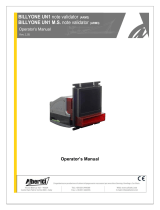
HopperOne S11
Std Pulse
Standard / Reverse
Operator’s Manual
HopperOne S11 Std Pulse
Operator’s manual
Rev. 1.02

2
1. General description
Congratulations for your purchase of the Alberici HopperOne S11!
This hopper has been designed and realized in the Alberici research laboratory.
It fulfils all the requirements of the coin-op market.
This belt drive single denomination dispensing device makes use of the most modern electronic and
mechanical technologies. It is secure, enduring, reliable.
1.1 Range of use
This hopper can count the amount of coins paid out, and to stop dispensing when empty.
To this purpose, it makes use of a significant quantity of control routines for the management of the
internal and external events.
It integrates easily into Gaming and Slot machines, Money Changers, Kiosks and Vending
Machines.
Its features make it easily compatible with all the control boards normally available on the market.
When matched to Alberici electronic coin selectors, the Hopper becomes the heart of change
machines, and it can be connected to our coin acceptor without any electronic interface.
1.2 Security
The HopperCD can be connected to and disconnected from its slide connector only when power
supply is off. The device includes mechanical parts in motion: DO NOT put your fingers inside it
during operation. The installation must be carried out as specified in paragraph 2.3. Guarantee
shall not apply if such instructions are not complied with.
2. Mechanical description
The HopperOne S11 cctalk is available in 2 different versions, according to the respective positions of
the electrical connector and the coins outlet. When they are located at opposite sides, the version is
named “STANDARD”; when they are located at the same side, the version is named “REVERSE”.
The standard features of the HopperOne S11 make it interchangeable with similar devices already existing
in the market. It can handle any coins whose diameter ranges between16 mm and 32 mm (choose the most
convenient belt for your purpose: 16-24mm, or else 22-32mm). Coin thickness can range between 2,0 mm
and 3,4 mm.
WARNING!
MECHANICAL PARTS
IN MOTION CAN BE
DANGEROUS FOR HANDS
AND FINGERS

3
2.1 Overall dimensions
2.2 Connector position
Reverse version
(connector located on the same side of the
output of the coins)
Standard version
(connector located on the opposite side of
the output of the coins)

4
2.3 Installation
. fasten the slide support,
. slide the hopper in
. for electrical connections, please see chapter 3
Please use conical head bolts
slide in
Floor surface of the cabinet
92mm
68.5mm
118mm
92mm
245mm
ø 5.5 mm

5
3. Electrical description
All the signals handled by the hopper are in negative logic: each signal is considered active when it
is LOW (GND).
3.1 CINCH connector Pin-Out
This connector can be found on the right side (standard) or left side (reverse) of the hopper.
The functions of the pins will be described in the next paragraphs.
3.2 Power Supply
This equipment must be supplied with 24V direct voltage.
The 24V version requires +24Vdc to pin10 for the operation of the logic card and +24Vdc to pin 9
for the operation of the motor.
The speed of coins dispensing is proportional to the voltage supplied to the motor. We recommend
to keep it between 18Vdc and 27Vdc.
A voltage of 24 Vdc produces 240 pcs. output per minute.
When the hopper level controls are made through optic sensors, do connect the electrode plates to the
machine ground terminals.
Current draw:
Stand-by No load Normal
operation
Stuck (*)
Board
(+24Vdc)
20mA/0,24W
20mA/0,24W
40mA/0,48W 40mA/0,48W
Motor
(+24Vdc)
0mA/0m W 70mA/1,4W 1,2 A/28.8W 1,5mA*/30W
Total 20mA/0,24 W
90mA/1,64W
1,24A/29,28W
1,54 /30,48W
*The motor overload current draw shall always be limited by the electronic circuit. The 1 A draw, corresponding to
hold-up of the motor, will therefore be reached only for a few msec.

6
3.3 Input signals
There are three available input signals: IN1 IN2 IN3 .
With these signals, it is possible to determine the modality of operation (see chapter 4), the reset of
the hopper and to start the dispensing.
The equivalent pins are IN1 pin4 To select the type of operation
IN2 pin8 To select the type of operation
IN3 pin12 To start the dispensing
3.4 Output signals
There are 5 output signals, that can perform 3 functions:
OUT1 , OUT2 , (See here below)
HIGH LEVEL SIGNAL (LH) , (See paragraph 3.5)
LOW LEVEL SIGNAL (LL),
ERROR.
OUT 1 and 2 :
The function performed by these outputs is to communicate (by a low signal) the dispensing of each
coin. The quantity of the impulses sent out is directly proportional to the number of tokens paid out
by the hopper.
OUT1 and OUT2 are practically identical: they can be used for sending the return signal to the
game card, or to possibly connect a counter or relay.
Such signals are open collector type. When the internal transistor is not in conduction, a pull up
resistor takes the output high (12 V).
The open collector technology provides a simple interface to TTL and CMOS input devices.
Pin3 corresponds to out1 and pin11 corresponds to out2.
3.5 Level signals
Low level signal (LL) pin 7:
For all those systems where it is important to monitor the level of coins remaining in the hopper, a
low level signal is transmitted as long as there are coins in the hopper, and an high level signal gets
triggered as the hopper gets empty or in reserve.
The high level of the signal is produced by a pull-up resistance, while the low level signal is kept by
the presence of the of the coins, whose metallic body is electrically connected to GND.
High level signal (HL) pin 6:
The same as in previous paragraph, but this time the high level signal corresponds to “coins in the
hopper”, whilst the low level signal corresponds to “empty hopper”.

7
4. FUNCTIONAL CONDITIONS
Determine in advance how your hopper must operate, since it will be necessary for you to choose
the type of operation best suitable for your requirements.
This hopper can work in three different ways, Type0 Type1 Type2 …
4.1 Selection of conditions
The selection of conditions can be made by IN1 and IN2 inputs (pin 4 and pin 8).
The logic state of these inputs is detected at the start.
The following table shows all the possible combinations to this purpose.
IN1 IN2
Type 0 1
(+24Vdc)
1
(+24Vdc)
Type 1 0
(GND)
0
(GND)
Type 2 1
(+24Vdc)
0
(GND)
RESET 0
(GND)
1
(+24Vdc)
4.2 Type 0
This operational modality distributes continually coins from the hopper.
The control of the motor is exclusively made through the 24 Vdc supply (pin 9).
4.3 Type 1
The 24 Vdc must always be at the relevant input, and the control of the distribution is made through
IN3 (pin12) by a negative signal.
This is the method commonly used
.
4.4 Type 2
It is the game card that counts the tokens / coins.
An internal 16 bit register counts the pulses in IN3. Then, as many coins as the registered pulses are
dispensed by the hopper.
The 16-bit register counts up to 65535 coins, more than any hopper can contain.
4.5 Reset
The reset simulates the switching-off, so it is not a functional condition but a command that can be
activated at any time.
It allows to restore correct operation, after an error occurred.
After an error the device can be either reset or switched off and on again.
The reset also allows to modify the type of operation on condition that IN1 and IN2 are re-
configured within one second from the removal of the signals that produce the reset.
This command and the control of IN1 and IN2 must be managed by your control machine.

8
®
Progettazione e produzione di sistemi di pagamento, accessori per videogames e macchine vending
Design and manufacture of payment systems, accessories for videogames and vending machines
Via Ca’ Bianca 421
40024 Castel San Pietro
Terme (BO) – ITALY
Tel. + 39 051 944 300
Fax. + 39 051 944 594
http://www.alberici.net
/