Page is loading ...

7228
Operator’s Manual
Single-Channel Industrial Amplier for Demanding, High-Power Systems
574.295.9495 | www.aetechron.com
2507 Warren Street, Elkhart, IN 46516

Three-Year, No-Fault Warranty
SUMMARY OF WARRANTY
AE TECHRON INC., of Elkhart, Indiana (Warrantor)
warrants to you, the ORIGINAL COMMERCIAL PUR-
CHASER and ANY SUBSEQUENT OWNER of each
NEW AE TECHRON INC. product, for a period
of three (3) years from the date of purchase, by
the original purchaser (warranty period) that the
product is free of defects in materials and work-
manship and will meet or exceed all advertised
specications for such a product. We further war-
rant the new AE Techron product regardless of
the reason for failure, except as excluded in the
Warranty.
ITEMS EXCLUDED FROM WARRANTY
This AE Techron Warranty is in eect only for failure
of a new AE Techron product which occurred within
the Warranty Period. It does not cover any product
which has been damaged because of any intentional
misuse, or loss which is covered under any of your
insurance contracts. This warranty does not extend
to any product on which the serial number has been
defaced, altered, or removed. It does not cover dam-
age to loads or any other products or accessories
resulting from AE TECHRON INC. product failure. It
does not cover defects or damage caused by the use
of unauthorized modications, accessories, parts, or
service.
WHAT WE WILL DO
We will remedy any defect, regardless of the reason
for failure (except as excluded), by repair or replace-
ment, at our sole discretion. Warranty work can only
be performed at our authorized service centers or at
our factory.
Expenses in remedying the defect will be borne by
AE TECHRON INC., including one-way surface
freight shipping costs within the United States.
(Purchaser must bear the expense of shipping the
product between any foreign country and the port of
entry in the United States and all taxes, duties, and
other customs fees for such foreign shipments.)
HOW TO OBTAIN WARRANTY SERVICE
When you notify us or one of our authorized service
centers of your need for warranty service, you will
receive an authorization to return the product for
service. All components must be shipped in a factory
pack or equivalent which, if needed, may be obtained
from us for a nominal charge. We will take corrective
actions and return the product to you within three
weeks of the date of receipt of the defective prod-
uct, or will make available to you a product of equal
or better performance on temporary loan until your
product can be repaired or replaced and returned to
you. If the repairs made by us are not satisfactory,
notify us immediately.
DISCLAIMER OF CONSEQUENTIAL AND
INCIDENTAL DAMAGES
You are not entitled to recover from us any conse-
quential or incidental damages resulting from any
defect in our product. This includes any damage to
another product or products resulting from such a
defect.
WARRANTY ALTERATIONS
No person has the authority to enlarge, amend, or
modify this warranty. The warranty is not extended by
the length of time for which you are deprived of the
use of this product. Repairs and replacement parts
provided under the terms of this warranty shall carry
only the unexpired portion of this warranty.
DESIGN CHANGES
We reserve the right to change the design of any
product from time to time without notice and with no
obligation to make corresponding changes in prod-
ucts previously manufactured.
LEGAL REMEDIES OF PURCHASER
There is no warranty that extends beyond the terms
hereof. This written warranty is given in lieu of any
oral or implied warranties not contained herein. We
disclaim all implied warranties, including, without
limitation, any warranties of merchantability or tness
for a particular purpose. No action to enforce this
Warranty shall be commenced later than ninety (90)
days after expiration of the warranty period.
This statement of warranty supersedes any others
contained in this manual for AE Techron products.
AE TECHRON INC.
Customer Service Department
2507 Warren St. Elkhart, IN, 46516, U.S.A.
(574) 295-9495
www.aetechron.c

DECLARATION OF CONFORMITY
Technical Construction File Route
Issued By: AE Techron, Inc. For Compliance Questions Only: Larry Shank
2507 Warren Street 574-295-9495
Elkhart, IN 46516 lshank@aetechron.com
This Declaration of Conformity is issued under the sole responsibility
of AE Techron, Inc., and belongs to the following product:
Equipment Type:Industrial Power Amplifiers
Model Name: 7228
EMC Standards:
EN 61326-1: 2013 – Electrical Equipment for Measurement, Control and Laboratory use
— EMC Requirements
EN 55011: 2009 + A1: 2010 – Industrial, Scientific and Medical (ISM) radio-frequency equipment
— Radio disturbance characteristics
— Limits and methods of measurement
EN 61000-4-2: 2009 – Electromagnetic compatibility (EMC) Part 4: Testing and measurement techniques:
Electrostatic discharge immunity test
EN 61000-4-3: 2006 + A2: 2010 – Electromagnetic compatibility (EMC) Part 4: Testing and measurement techniques:
Radiated radio-frequency electromagnetic field immunity test
EN 61000-4-4: 2012 – Electromagnetic compatibility (EMC) Part 4: Testing and measurement techniques:
Electrical fast transient/burst immunity test
EN 61000-4-5: 2006 – Electromagnetic compatibility (EMC) Part 4: Testing and measurement techniques:
Surge immunity test
EN 61000-4-6: 2009 – Electromagnetic compatibility (EMC) Part 4: Testing and measurement techniques:
Immunity to conducted disturbances induced by radio frequency field
EN 61000-4-8: 2010 – Electromagnetic compatibility (EMC) Part 4: Testing and measurement techniques:
Power frequency magnetic field immunity test
EN 61000-4-11: 2004 – Electromagnetic compatibility (EMC) Part 4: Testing and measurement techniques:
Voltage dips, short interruptions and voltage variations immunity test
Safety Standard:
BSEN61010-1:2010 (inc Corr. May 2011) – Safety requirements for electrical equipment for measurement, control, and laboratory use
I certify that the product identified above conforms to the requirements of the EMC Council Directive 2014/30/E, and the Low Voltage Directive 2014/35/EU.
Signed:
Larry Shank Place of Issue: Elkhart, IN, USA
President Date of Issue: August 16, 2017
CE Affixing Date: August 7, 2017

Contents
1 Introduction ....................................................................................................................................5
1.1 Features ................................................................................................................................5
1.2 Conguration Options............................................................................................................5
2 Amplier Unpacking and Installation ..............................................................................................6
2.1 Safety First ............................................................................................................................6
2.2 Unpacking
.............................................................................................................................6
2.3 Installation .............................................................................................................................6
3 Connections and Startup ...............................................................................................................7
3.1 Other Operation Modes and Congurations..........................................................................7
3.2 Connecting the Load .............................................................................................................7
3.3 Connecting the Input Signal ..................................................................................................8
3.4 Other DIP Switch Settings ..................................................................................................9
3.5 Using the Expansion Port ................................................................................................... 9
3.6 Connecting the AC Supply ....................................................................................................9
3.7 Start-up Procedure ................................................................................................................9
4 Amplier Operation ......................................................................................................................10
4.1 Front-Panel Controls ...........................................................................................................10
4.2 Front-Panel Indicators .........................................................................................................12
4.3 Back-Panel Controls and Connectors .............................................................................. 14
5 Advanced Conguration ............................................................................................................... 15
5.1 DIP Switch Congurations ...................................................................................................15
5.2 Internal Jumpers and Settings.............................................................................................18
6 Applications
..................................................................................................................................22
6.1 Power Supply Settings for Increased Voltage or Current ....................................................22
6.2 Multi-amp Systems for Increased Voltage or Current..........................................................23
6.3 DB-62 Expansion Port Applications.....................................................................................31
6.4 Controlled Current Operation ..............................................................................................38
6.5 DC Servo .............................................................................................................................43
6.6 Current Limiting ...................................................................................................................43
7 Maintenance
................................................................................................................................44
7.1 Clean Amplier Filter and Grills ...........................................................................................44
8 Troubleshooting
...........................................................................................................................45
8.1 Introduction & Precautions ..................................................................................................45
8.2 Visual Inspection .................................................................................................................45
8.3 No Signal .............................................................................................................................45
8.4 No LEDs Illuminated............................................................................................................45
8.5 OverVoltage LED Lit ............................................................................................................ 45
8.6 Standby and Stop LEDs Remain Illuminated ......................................................................46
8.7 Standby LED Remains Illuminated......................................................................................46
8.8 Amplier Overheats (Over Temp Fault Condition) ...............................................................46
8.9 Fault LED is Illuminated ......................................................................................................47
8.10 Factory Service .................................................................................................................47
9 Specications
...............................................................................................................................48

97-8004188_08-31-2020
Information subject to change
5
7228 OPERATOR’S MANUAL – SECTION 1
1 Introduction
Congratulations on your purchase of the 7228
power amplier. The 7228 was developed to bring
performance improvements and an extended fea-
ture set when compared to AE Techron’s industry
standard 7224 amplier. The 7228 ampliers are
built and tested to the most stringent quality stan-
dards for long life and outstanding performance.
The AE Techron brand is known throughout the
world for its robust precision ampliers as well as
its product service and support.
1.1 Features
The 7228 is a single-channel linear amplier de-
signed for use in demanding applications requiring
very low noise, low distortion, and accurate power
amplication from DC to 1 MHz. It features:
• Output of over 1,000 watts RMS at 8 ohms
continuously for 45 minutes.
• 40 mSec pulses of up to 60 amperes peak into
a 0.5 ohm load.
• Fast configuration in the field using back-panel
DIP switches; includes user-variable current
limit, DC blocking, DC Servo, multiamp, and
more.
• Offers precision control of output offset, DC
drift and gain linearity.
• Variable-speed fans minimize noise while
optimizing output.
• Protection circuitry protects the AE Techron
7228 from input overloads, improper output
connection (including shorted and improper
loads), over-temperature, over-current, and
supply voltages that are too high or low.
• Ground loop and circulating current protection
includes a protection circuit that temporarily
forces the amplifier to Standby.
1.2 Conguration Options
The 7228 can be easily congured in the eld
using back-panel DIP switches or remote contact
closure. Conguration options include:
• DC Block enable/disable
• User-variable current limit
• DC Servo enable/disable
• Switch between supply rail modes and voltages
to optimize for various load impedances
• Change from controlled-voltage to controlled-
current operation
• Parallel operation
• Series operation
Figure 1.1 – 7228 Front Panel
Performance Overview
Small Signal Bandwidth DC - 1 MHz
Max Continuous Power, 20 kHz 1000 watts
Max Continuous Power, 150 kHz 400 watts
Current Limit 60A
Slew Rate 100V/µs
DC Drift 200 µV*
*With DC Servo enabled.

Information subject to change
97-8004188_08-31-2020
7228 OPERATOR’S MANUAL – SECTION 2
6
2 Amplier Unpacking and
Installation
The 7228 amplier is a precision instrument that
can be dangerous if not handled properly. Lethal
voltages are present in both the AC input supply
and the output of the amplier. For this reason,
safety should be your primary concern when you
setup and operate this amplier.
2.1 Safety First
Throughout this manual special emphasis is
placed on good safety practices. The following
graphics are used to highlight certain topics that
require extra precaution.
Along with any additional accessories purchased
by the customer, all 7228 ampliers ship with the
following:
• 7228 Amplifier
• Toolkit (contains one #2 Phillips screwdriver
and four rubber feet)
• Power Cord
• 7228 Operator’s Manual and Quick Start sheet
2.3 Installation
The 7228 ampliers are packaged in a rugged
powder-coated aluminum chassis. This chassis is
2U (rack units) tall, and has rack “ears” on each
side of the front panel for mounting to a standard
EIA (Electronic Industries Association) rack. Use
standard rack mounting hardware to mount the
amplier. Use nylon washers if you wish to protect
the powder-coat nish on the front of the amplier.
Optionally, the amplier can be placed on a
bench top; please keep in mind that the protective
powder-coating can be scratched when placed
on other equipment or on a bench top, especially
when there is dirt present. To protect the nish, a
set of rubber feet is included in the toolkit that can
be installed on the bottom of the amplier.
Allow ample space on the sides and especially
the back of the amplier for heated air to escape.
The amplier should be mounted in a rack that is
adequately ventilated and not sealed. Likewise,
the front of the amplier should be unobstructed to
allow cool air to enter the amplier.
DANGER represents the most severe
hazard alert. Extreme bodily harm or
death will occur if these guidelines are
not followed. Note the explanation of the
hazard and instruction for avoiding it.
DANGER
WARNING alerts you to hazards that
could result in severe injury or death.
Note the explanation of the hazard and
the instructions for avoiding it.
WARNING
CAUTION indicates hazards that could
result in potential injury or equipment
or property damage. Once again, note
the explanation of the hazard and the
instructions for avoiding it.
CAUTION
Do not operate the amplier in a small
sealed chamber of any kind. Improper
operations and overheating will result.
CAUTION
2.2 Unpacking
All ampliers are tested and inspected for dam-
age before leaving the factory. Carefully unpack
and inspect the amplier for damage. Please note
any damage for future reference and notify the
shipping company immediately if damage is
found.
Also, please save the shipping carton and
materials as evidence of damage and/or for return-
ing the amplier for repair.

97-8004188_08-31-2020
Information subject to change
7
7228 OPERATOR’S MANUAL – SECTION 3
3 Connections and Startup
This section details the wiring and startup pro-
cedures for a single 7228 amplier operating in
Controlled-Voltage mode (factory default). Before
connecting the amplier, make sure the AC power
cord is unplugged.
3.1 Other Operation Modes and
Congurations
The 7228 amplier can be eld-congured for
operation in a number of ways. The amplier can
be operated in Controlled-Voltage or Controlled-
Current mode. It also can be congured for opera-
tion as a part of a multi-amplier system. These
alternate congurations may require special output
wiring and/or additional components.
3.1.1 Controlled-Current Operation of a
Stand-Alone Amplier
IMPORTANT:
If your application requires Con-
trolled Current operation, the 7228 amplier rst
should be wired and tested in Controlled-Voltage
mode to verify that the amplier and input signal
are operating correctly. Once proper operation is
conrmed, refer to the Applications section of this
manual for instructions on conguring and operat-
ing your amplier in Controlled-Current mode.
3.1.2 Multi-Amp Operation
If your application requires multi-amp operation for
increased voltage or current, each amplier should
rst be wired and tested individually in Controlled-
Voltage mode to ensure proper operation.
For Series operation in Controlled-Voltage
mode,
refer to the topic “Multiamp Systems for
Increased Current or Voltage” in the Applications
section of this manual for information on Series
system conguration.
For Series operation in Controlled-Current
mode,
you should select one amplier to be oper-
ated as the “Master” amplier of the system, and
then refer to the topic “Controlled Current Opera-
tion” in the Applications section of this manual for
instructions on conguring this amplier for opera-
tion in Controlled-Current mode. After the Master
amplier is congured and tested for Controlled-
Current operation, refer to the topic “Multiamp
Systems for Increased Current or Voltage” in the
Applications section of this manual for informa-
tion on Series system conguration.
For Parallel operation in Controlled-Voltage
mode,
refer to the topic “Multiamp Systems for
Increased Current or Voltage” in the Applications
section of this manual for information on Parallel
system conguration.
CAUTION: DO NOT operate paralleled ampli-
ers in Controlled-Current mode without rst
contacting AE Techron Technical Support for
assistance.
3.2 Connecting the Load
3.2.1 Preparation and Cautions
Before connecting the amplier, make sure the
AC power is disconnected.
Figure 3.1 – 7228 Back Panel
ELECTRIC SHOCK HAZARD.
Output potentials can be lethal. Make
connections only with AC Power OFF
and input signals removed.
WARNING

Information subject to change
97-8004188_08-31-2020
7228 OPERATOR’S MANUAL – SECTION 3
8
Figure 3.2 – Connecting the Load
Always use the appropriate wire size and insula-
tion for the maximum current and voltage expected
at the output. Never connect the output of the
amplier to any other model amplier, power sup-
ply, signal source, or other inappropriate load; re
can result.
3.2.2 Connecting the Outputs
Connection to the output of the amplier is to a
3-position terminal strip with #8 screws. Wires
terminated with #8 ring terminals, tinned wires up
to 10 AWG in size, or bus bars with 0.18 in. (4.6
mm) holes are recommended when connecting to
the output terminals. Connect the load across the
terminals marked “OUTPUT” (positive) and “COM”
(negative/ground). The third terminal, “CHASSIS
GROUND” can be connected to an external ground
point such as the rack chassis. See Figure 3.2.
IMPORTANT: DO NOT connect the load to the
“CHASSIS GROUND” terminal.
Figure 3.3 – Wiring for Unbalanced or Balanced
Input Connector
high quality and shielded to minimize noise and to
guard against possible feedback.
DIP switch #5, located on the DIP switch panel
above the SIM card, can be used to select bal-
anced or unbalanced input wiring, and also can
function as a ground-lift switch for the BNC input
connector (see Figure 3.4). DIP switch #5 func-
3.3 Connecting the Input Signal
The signal is connected to the amplier through a
“SIM” (Specialized Input Module) card located on
the amplier back panel. This standard SIM2 BNC
card can easily be removed and replaced with
alternate SIM cards designed for special applica-
tions, when required.
The SIM2 BNC card provides both an unbalanced
Input BNC jack and a balanced Input “WECO”
terminal block connector. Connect your input
signal to the unbalanced or balanced input con-
nector as shown in Figure 3.3.
Use cables that are
Figure 3.4 – DIP Switch Panel Location
Figure 3.5 – Wiring for Unbalanced or Balanced
Input Connector

97-8004188_08-31-2020
Information subject to change
9
7228 OPERATOR’S MANUAL – SECTION 3
tions by connecting/disconnecting the inverting (–)
pin on each input connector to the amplier ground
through a 5-ohm resistor (see Figure 3.5).
When DIP switch #5 is placed in the UP position
(factory default), the shield on the BNC connector
and the inverting (–) pin on ther terminal block con-
nector are tied to the amplier ground, allowing the
connectors to be used for Unbalanced input wiring.
When DIP switch #5 is placed in the DOWN posi-
tion, the inverting pin on the terminal block connec-
tor is oating, allowing the connector to be used for
balanced input wiring.
IMPORTANT: DIP switch #5 can also function
as a Ground Lift switch for the BNC Input con-
nector. If circulating currents/ground loops/60-
Hz Hum occur when using the BNC Input,
move DIP switch #5 to the DOWN position to
lift the ground on the connector.
3.4 Other DIP Switch Settings
Other DIP switches can be used to enable features
or congure the amplier for special applications.
See the Advanced Conguration section of this
manual for more informaiton. Before operating the
amplier, check to make sure all DIP switches are
set as intended. The factory default setting for all
DIP switches is the UP position.
3.5 Using the Expansion Port
The Expansion Port can be used to provide remote
control and monitoring of the amplier. See the
Applications section of this manual for informa-
tion on using the Expansion Port connector for
remote applications.
Figure 3.6 – Closeup of AC Mains Outlet
3.6 Connecting the AC Supply
The power cord connects to a standard 20A 3-pin
IEC-type male connector on the back panel (see
Figure 3.6). Make sure the Breaker/Switch on the
front panel is switched to the OFF (O) position.
Make sure the power cord is inserted and seated
fully into the IEC connector by moving it slightly
back and forth and up and down while pushing
in. The power cord is relatively sti and should be
routed so that there is no excessive force pulling to
the sides or up or down that would stress the pins
or internal connections.
3.7 Start-up Procedure
1. Turn down the level of your signal source.
2. Turn down the gain control of the amplier.
3. Depress the POWER switch to turn the
amplier ON.
4. Wait for the yellow READY and green RUN
LEDs to illuminate.
5. Turn up the Gain control on the amplier
until the desired voltage or power level is
achieved.
6. Adjust the input signal level to achieve the
desired output level.

Information subject to change
97-8004188_08-31-2020
7228 OPERATOR’S MANUAL – SECTION 4
10
4 Amplier Operation
4.1 Front-Panel Controls
This section provides an overview of Front-Panel
controls and indicators found on the 7228.
4.1.1 Power Switch
The Power Switch controls the AC mains power to
the amplier. Switch to the ON position (|) to turn
the amplier on. Switch to the OFF position (O) to
turn the amplier o. See Figure 4.1.
The Power Switch also serves as a Breaker. When
the Breaker is tripped, the Power Switch moves to
a neutral position between ON and OFF. To reset
the Breaker, turn the amplier OFF (O) and then
turn it back ON (I).
4.1.2 Gain Control
The Gain Control Knob increases/decreases the
gain from 0 – 100% of the overall Gain (factory
default Gain is 20V/V in voltage mode and 5A/V in
current mode). Turn the Gain Control fully clock-
wise for maximum amplier output. See Figure
4.2. See the Advanced Conguration section for
information on how to make the amplier xed-
gain.
4.1.3 Push Buttons
Run and Standby Conditions
The 7228 provides three front-panel soft-touch
Push Buttons that control two basic operating
conditions: (1) Run condition (the high-voltage
transformers are energized and the unit will am-
plify the input signal); and (2) Standby condition
(the low-voltage transformer is energized but the
high-voltage transformers are not and the unit will
not ampliy the input signal).
By default, the amplier will automatically enter
the Run condition on power-up. To change the
factory-default setting and congure the amplier
to power-up in Standby/Stop mode, please see the
Advanced Conguration section.
The amplier will enter one of four Standby modes
under the following conditions:
Standby mode (Standby LED lit): The ampli-
er will enter Standby mode if the Ground Loop
Protection Circuit detects a ground loop or excess
circulating currents. Eliminate the ground loop and
the amplier will automatically return to Run mode.
In addition, setting improper DIP switch combina-
tions will cause the amplier to enter Standby
mode.
1. If the DC Servo DIP switch (#11) is set in
the DOWN position while the Input Cou-
pling DIP switch (#6) is set in the UP posi-
tion, the amplier will enter Standby mode.
Change the DC Servo switch to the UP po-
sition or change the Input Coupling switch
to the DOWN position, and the amplier
will automatically return to Run mode.
2. If the Current Limit DIP switches (#13 to
#16) are all placed in the DOWN position,
the amplier will enter Standby mode.
Change as least one of these four switches
Figure 4.1 – Power Switch
Figure 4.2 – Gain Control

97-8004188_08-31-2020
Information subject to change
11
7228 OPERATOR’S MANUAL – SECTION 4
to the UP position and the amplier will
automatically return to Run mode.
Remote Standby mode (Ready and Standby
LEDs lit):
The amplier is functioning properly and
all Fault Status modes are clear, but the unit has
been placed in Standby by an external condition.
If the amplier has been congured as a Series
Follower (DIP switch #1 DOWN), it will enter
Remote Standby mode when the Enable button is
pressed and remain in that mode until it receives
the Enable signal from an interlocked Master am-
plier.
If an amplier is disabled using a Remote Standby
switch, the amplier will be placed in Remote
Standby mode. To return the amplier to a Run
condition, release the Standby condition using the
remote switch. See the Applications section of
this manual for more information on remote ampli-
er operation.
Standby/Fault mode (Standby and one or more
Fault LEDs lit):
The amplier has been placed in
Standby due to an Output, Overload, Over Temp
or Over Voltage condition. See the section “Fault
Status Indicators” to determine the fault condition
being indicated and the action required to clear the
fault condition.
Standby/Stop mode:
The amplier has been
placed in Standby due to a Stop order or a Stop
condition: The Stop button on the amplier front
panel has been pushed, some DIP switches have
been changed or placed in improper congura-
tions, or the amplier has been congured to enter
Stop mode on startup. See the “Advanced Con-
guration”
section for information about congur-
ing the amplier for Startup in Stop mode.
Enable, Stop and Reset Buttons
The following details the results when each of the
three Push Buttons are pressed on the amplier
front panel. See Figure 4.3 for Push Button loca-
Figure 4.4 – Main Status and Fault Status Indicators
tions.
Enable –
When the amplier is in Standby/Stop
mode, pressing the Enable button will release the
amplier from Standby and place the amplier in
Run mode. If the Enable button does not release
the amplier from Standby/Stop mode, check to
see if both the Series Mode (#1) and Parallel Mode
(#2) DIP switches are in the DOWN position. Place
one or both switches in the UP position and then
press the Enable button to release the amplier
from Standby/Stop mode.
Stop – Pressing the Stop button will place the
amplier in Standby/Stop mode (both Standby and
Stop LEDs will be lit).
Reset – When the amplier has been placed
in Standby/Fault mode due to a fault condition,
pressing the Reset button will return the amplier
to Run mode if the condition causing the fault con-
dition has been cleared and the amplier has been
congured for startup in Run mode. If the ampli-
er has been congured for startup in Stop mode,
pressing the Reset button will place the amplier
in Standby/Stop mode. Press the Enable button to
Figure 4.3 – Push Buttons

Information subject to change
97-8004188_08-31-2020
7228 OPERATOR’S MANUAL – SECTION 4
12
return the amplier to Run mode.
4.2 Front-Panel Indicators
4.2.1 Main Status Indicators
Four Main Status indicators are located on the am-
plier’s front-panel (see Figure 4.4). These LEDs
Figure 4.5 – Main Status Indicators
Indicator is lit Indicator is not lit Indicator may be lit
Main Status
Indicators State of Operation Action Needed to Return to Run Mode
Run
Ready
Standby
Stop
Run mode: The amplier’s high-voltage
transformers are energized and the unit will
amplify the input signal. Run mode is initiated
by: (1) the Enable push button, or (2) when
the amplier powers up in Run mode (factory
default). See the Advanced Conguration
section for more information.
N/A
Run
Ready
Standby
Stop
Standby mode: Standby mode indicates
that the amplier has been placed in Standby
because: 1) Ground loop and/or circulating
currents have triggered the ground-loop pro-
tection circuit; or 2) Some combinations of DIP
switches have been set improperly. In Standby
mode, the amplier’s low-voltage transformer
is energized but the high-voltage transformers
are not.
Check to see if one of the following improper DIP switch
combinations has been set: #6 UP and #11 DOWN,
or #13 - #16 all DOWN. To release the amplier from
Standby mode, change the improper setting and the
amplier will automatically return to Run mode. If the
switches are set properly but the amp remains in Stand-
by, eliminate ground loop conditions and the amp will
automatically return to Run mode.
Run
Ready
Standby
Stop
Remote Standby mode: Remote Standby
mode indicates that the amplier is functioning
properly and all Fault Status modes are clear,
but it is being held in Standby by an exter-
nal condition. As congured from the factory
(Run mode on startup), the amplier will enter
Remote Standby mode briey after powering
up, and then will move automatically into Run
mode. In Remote Standby mode, the ampli-
er’s low-voltage transformer is energized but
the high-voltage transformers are not.
If the amplier remains in Remote Standby mode, it is:
1) Being held in Standby by remote control through the
Expansion Port; or 2) Has been congured as a Follower
amplier for Series operation. If the amplier has been
congured as a Series Follower (DIP switch #1 DOWN),
it will automatically enter Run mode when the interlocked
Master amplier enters Run mode. Or place DIP switch
#1 in the UP position and then press the Enable button
to return to Run mode. If the amp has a remote Standby
switch, ctivate the switch to clear the Remote Standby
condition and return the amplier to Run mode. See the
Applications section of this manual for more information
on remote amplier operation.
Run
Ready
Standby
Stop
Standby/Stop mode: The amplier will
enter Standby/Stop mode: 1) When the Stop
button on the amplier front panel is pressed;
2) After powering up if the amplier is cong-
ured to enter Stop mode on startup; 3) When
certain DIP switch settings are changed while
the amplier is in Run mode; or 4) When
both Series Mode (SW#1) and Parallel Mode
(SW#2) are placed in the DOWN position.
In Standby/Stop mode, the amplier’s low-
voltage transformer is energized but the high-
voltage transformers are not.
To release the amplier from Standby/Stop mode, press
the Enable button. If the amplier will not release from
Standby/Stop mode, check to see if both DIP switches
#1 and #2 are in the DOWN position. Place one or both
switches in the UP position, and then press the Enable
button to release the amplier from Standby/Stop mode.
monitor the internal conditions of the amplier and
indicate the current state of operation. The chart in
Figure 4.5 details the operational modes indicated
by the Main Status indicators.
NOTE: See the “Applications” section for main

97-8004188_08-31-2020
Information subject to change
13
7228 OPERATOR’S MANUAL – SECTION 4
Figure 4.6 – Fault Status Indicators
Indicator is lit Indicator is not lit Indicator may be lit
Main Status
Indicators
Fault Status
Indicators State of Operation
Action Needed to Clear Fault
Condition and Return to
Run Mode
Run
Ready
Standby
Stop
Fault
Over Load
Over Temp
Over Voltage
Output Fault status: This indicates
that an Output Fault condition has oc-
curred and the amplier has been placed
in Standby mode. The Fault indicator
will light under two conditions: 1) High-
frequency oscillation is causing high
shoot-through current; or 2) An output
transistor has shorted, causing the output
fault condition.
This fault condition cannot be cleared
using the front-panel Reset button. See
the Troubleshooting section for more
information on diagnosing and clearing
this fault condition.
Run
Ready
Standby
Stop
Fault
Over Load
Over Temp
Over Voltage
Over Load status: This indicates that
the output of the amplier could not follow
the input signal due to voltage or current
limits. Under normal operation with the
factory-default settings, an Over Load
condition will not place the amplier in
Standby mode. If the amplier has been
congured to be forced to Standby on
Over Load, the amplier will be placed in
Standby mode when the Over Load indica-
tor lights.
To remedy the Over Load fault during
operation, turn down the level of the input
signal until the Over Load indicator turns
o. To clear an Over Load fault condition
when the amplier is forced to Standby,
turn down the level of the input signal,
then push the Reset button.
Run
Ready
Standby
Stop
Fault
Over Load
Over Temp
Over Voltage
Over Temp status: The amplier
monitors the temperature inside the high-
voltage transformers, low-voltage trans-
former and in the output stage heat sinks.
The Over Temp indicator will light and the
amplier will be placed in Standby mode
when the temperature sensors detect a
condition that would damage the ampli-
er. If the Over Temp pulse is extremely
short, as in the case of defective wiring or
switches, the Over Temp LED may be lit
too briey to observe.
To reset after an Over Temp fault has
occurred, make sure the fans are running,
and then remove the input signal from the
amplier. Note that the fans will automati-
cally switch to high-speed operation on
an Over Temp condition. Allow the fans
to run for about 5 minutes, or until the
fans switch to low-speed operation (fans
will not move to low-speed operation if
they have been congured for continuous
high-speed operation). Push and hold the
Reset button until the Standby LED turns
o, and then release the Reset button to
return the system to Run mode. See the
Troubleshooting section for information
on correcting the cause of an Over Temp
fault condition.
Run
Ready
Standby
Stop
Fault
Over Load
Over Temp
Over Voltage
Over Voltage status: This indicates
that the AC mains voltage is more than
+10% of nominal. The amplier will be
forced to Standby when an Over Voltage
condition occurs. When the Over Voltage
condition is cleared, the amplier will auto-
matically return to Run mode.
To clear an Over Voltage fault condition,
the AC mains must be brought down to
the nominal value. Once the Over Voltage
condition has been cleared, press the
Reset button to return the amplier to
Run mode. If the amplier does not return
to Run mode, the amplier may require
servicing. Please see the Troubleshoot-
ing section for more information.
status indicator interpretation when operating a
multi-amp system.
4.2.2 Fault Status Indicators
Four Fault Status indicators are located on the
amplier front panel (see Figure 4.4). These LEDs
monitor the internal conditions of the amplier
and will illuminate when a fault condition occurs.
Depending on the fault condition and the congu-

Information subject to change
97-8004188_08-31-2020
7228 OPERATOR’S MANUAL – SECTION 4
14
ration of the unit, the amplier may be placed in
Standby/Fault mode when a fault condition oc-
curs. Refer to the chart in Figure 4.6 to determine
the fault condition being indicated and the action
required to clear the fault condition.
NOTE: See the “Applications” section for fault
status indicator interpretation when operating a
multi-amp system.
4.3 Back-Panel Controls
and Connectors
This section provides an overview of Back-Panel
controls and connectors found on the 7228. Please
refer to Figure 4.7 for visual locations.
AC Supply –
Standard 20 amp 3-pin IEC-type
male connector.
Output Terminal Strip –
Connect output lines
from the load to this 3-position terminal strip with
#8 screws. It accepts up to 10 AWG wire.
Unbalanced BNC Input Connector – This input
option provides a standard unbalanced input.
Balanced WECO Input Connector – This input
option provides a balanced input.
Expansion Port – This 62-pin, D-sub connector
can be used for a variety of remote control and
monitoring applications. It is also used for inter-
locking and combining functions in a system of
multiple ampliers. See the “Applications” sec-
tion for more information.
Figure 4.7 – Back Panel Controls and Connectors

97-8004188_08-31-2020
Information subject to change
15
7228 OPERATOR’S MANUAL – SECTION 5
5 Advanced Conguration
The 7228 amplier was designed to oer excep-
tional versatility in operation. You can choose from
a range of eld-congurable options, including:
• Operate as a stand-alone amplifier or as part of
a multiple-amplifier system.
• Select DC-coupled or AC-coupled operation.
• Select Controlled-Current or Controlled-Voltage
modes of operation.
• Configure the bi-level power supply for use in
high voltage applications, high current applica-
tions, or for applications requiring mid-level
amounts of both voltage and current.
• Limit current output via programmable current
limits.
• Enable DC Servo to ensure DC offset remains
at zero and safely drive coils and transformers.
• Change the maximum amplifier gain from 20:1
to 6:1.
• Operate with variable gain control or at a fixed
gain setting of 20.
• Configure the amplifier to enter Standby on
startup
• Configure the amplifier to enter Standby when
an overload condition occurs.
• Configure the automatic multi-speed fans to
operate always on high-speed, or always on
low-speed with an automatic change to high
speed when required.
5.1 DIP Switch Congurations
The 7228 amplier provides 16 DIP switches lo-
cated on the amplier back panel above the SIM2
BNC card. Most conguration settings can be
made using these DIP switches. See Figure 5.1
for DIP switch settings and descriptions.
SW#1: Series Mode
When this switch is in the UP position (default), the
amplier will function as a stand-alone amplier or
as a Master amplier in a series-connected multi-
amp system. When this switch is in the DOWN
position, the amplier will function as a Follower
amplier in a Series multi-amp system.
NOTE: If the Series Mode DIP switch is placed in
the DOWN position while the amplier is enabled,
the amplier will temporarily be placed in Standby/
Stop mode. Press the Enable button to release the
Figure 5.1 – DIP Switch Settings and Descriptions

Information subject to change
97-8004188_08-31-2020
7228 OPERATOR’S MANUAL – SECTION 5
16
amplier from Standby/Stop mode and enter Re-
mote Standby mode. The amplier will remain in
Remote Standby mode until it receives the Enable
signal from an interlocked Master amplier.
If the Series Mode DIP switch is placed in the
DOWN position while the Parallel Mode DIP switch
is also in the DOWN position, the amplier will
be placed in Standby/Stop mode. Pressing the
Enable button will not release the amplier until at
least one of the Series Mode or Parallel Mode DIP
switches is placed in the UP position.
For more information on multi-amplier system
conguration and operation, see the Applications
section.
SW#2: Parallel Mode
When this switch is in the UP position (default), the
amplier will function as a stand-alone amplier or
as a Master amplier in a multi-amp system. When
this switch is in the DOWN position, the amplier
will function as a Follower amplier in a Parallel
multi-amp system.
NOTE: If the Parallel Mode DIP switch is placed
in the DOWN position while the Series Mode DIP
switch is also in the DOWN postion, the amplier
will be placed in Standby/Stop mode. Pressing the
Enable button will not release the amplier until at
least one of the Series Mode or Parallel Mode DIP
switches is placed in the UP position.
For more information on multi-amplier system
conguration and operation, see the Applications
section.
SW#3: Parallel Matching
The Parallel Matching function serves to minimize
circulating currents when multiple ampliers are
used in a parallel conguration. When enabled, the
Parallel Matching function progressively increases
impedance from the voltage gain as current
increases, up to a mamimum 0.10-ohm increase.
This allows the ampliers to operate in parallel
without the use of separate ballast resistors in
multi-amp applications up to 20 kHz. For more
information on multi-amplier system conguration
and operation, see the Applications section.
When the Parallel Matching DIP switch is in the UP
position (default), the Parallel Matching function is
disabled. When this switch is in the DOWN posi-
tion, Parallel matching is enabled.
SW#4: Signal Ground
When the Signal Ground DIP switch is in the UP
position (default), the amplier’s negative (–)
output terminal is connected to ground through a
PTC (resettable fuse) that protects the amplier
from ground loops, circulating currents, and other
potentially harmful conditions. The PTC will toler-
ate up to 30V delta between signal and chassis
ground before a fault condition is triggered and
the amplier is placed in Standby. To release the
amplier from Standby, remedy the cause of the
fault condition, and the amplier will automatically
be returned to operational conditions.
When this switch is in the DOWN position, the
PTC is bypassed, disabling the Ground Loop pro-
tection.
Bypassing the PTC connection is required for
proper Series operation, but this is done automati-
cally when the Series Mode DIP switch (SW #1)
is placed in the DOWN position, so changing the
Signal Ground DIP switch setting is not required
for proper Series operation. For more information
on multi-amplier system conguration and opera-
tion, see the Applications section.
NOTE:
If the Signal Ground DIP switch is placed in
the DOWN position while the amplier is enabled,
the amplier will temporarily be placed in Standby/
Stop mode. Press the Enable button to release the
amplier.
SW#5: Input Signal
When the Input Signal DIP switch is in the UP
position (default), the negative (–) pole of the
input connector is connected to ground on both
the BNC and the WECO input connectors. In this
conguration, both BNC and WECO input connec-
tors can operate as unbalanced inputs. When this
switch is in the DOWN position, signal ground is
disconnected from the negative pole on both input
connectors. In this conguration, the switch func-
tions as a ground-lift switch for the BNC connector

97-8004188_08-31-2020
Information subject to change
17
7228 OPERATOR’S MANUAL – SECTION 5
and allows the WECO connector to function as a
balanced input.
SW#6: Input Coupling
When the Input Coupling DIP switch is in the UP
position (default), the amplier can receive and
amplify both DC and AC signal. When this switch
is in the DOWN position, a 2-Hz high-pass lter on
the inputs prevents the transmission of DC signal.
NOTE: Both the Input Coupling and DC Servo DIP
switches must be placed in the DOWN position
when activating the DC Servo function. Placing the
Input Coupling DIP switch in the UP position and
the DC Servo DIP switch in the DOWN position will
cause the amplier to be placed in Standby/Stop
mode. To return the amplier to operational condi-
tions, set both the DC Servo and the Input Cou-
pling DIP switches in the DOWN position or place
the DC Servo Switch in the UP position.
suitable for your application. For more information
on Controlled-Current operation, including how to
determine and congure a custom compensation
network, see the Applications section.
NOTE:
If the Controlled Mode DIP switch set-
ting is changed while the amplier is enabled, the
amplier will temporarily be placed in Standby/
Stop mode. Press the Enable button to release the
amplier.
SW#8: Bi-level Mode
When the Bi-level Mode DIP switch is in the UP
position (default), the amplier will automatically
switch the power supply transformers between a
series and a parallel conguration, depending on
the present voltage requirements of the applica-
tion. When this switch is in the DOWN position,
the amplier will not switch automatically, but will
operate according to the Manual Bi-level Mode
DIP switch setting (SW #9). For more information
on how to set the Bi-level Mode DIP switch for
increased voltage or current, see the Applications
section.
SW#9: Manual Bi-level Mode
The Manual Bi-level Mode switch is enabled when
the Bi-level Mode switch (SW#8) is set to Manual
(DOWN position). Once enabled, the amplier
will operate with the power supply transformers in
a series conguration when the Manual Bi-level
Mode DIP switch is in the UP position (default).
When this switch is in the DOWN position, the am-
plier will operate with the power supply transform-
ers in a parallel conguration. For more informa-
tion on how to set the Manual Bi-level Mode DIP
switch for increased voltage or current, see the
Applications section.
SW#10: Power Supply Rail Mode
When the Power Supply Rail Mode DIP switch is in
the UP position (default), the amplier will operate
with the power supply rails in a series congura-
tion for high-voltage output. When this switch is in
the DOWN position, the amplier will operate with
the power supply rails in a parallel conguration for
high-current output. For more information on how
to set the Power Supply Rail Mode DIP switch for
In Controlled-Current Mode, the load is part of the ampli-
er circuit, and the relationship of the load to the amplier is
critical. For proper and safe operation in Controlled-Current
mode, you must observe the following guidelines:
1. Properly attach a load before operating the amplier.
2. DO NOT use a blocking capacitor. The load must have a
DC path.
3. Never leave the load open. If you feel the load must be
fused, which could lead to a potential open circuit, please
contact AE Techron Technical Support.
4. Make sure the load has some inductive component.
5. Provide appropriate compensation for the load.
6. If oscillation occurs, turn o the amplier immediately.
Failure to follow these guidelines may result
in damage to the amplier or load.
CAUTION
SW#7: Controlled Mode
When the Controlled Mode DIP switch is in the
UP position (default), the amplier will operate
in Controlled-Voltage mode, and the amplier’s
output voltage will be controlled by its input voltage
signal. When this switch is in the DOWN position,
the amplier will operate in Controlled-Current
mode, and the amplier’s output current will be
controlled by its input voltage signal.
IMPORTANT: Controlled-Current operation re-
quires the use of a compensation network, and the
7228’s default compensation network may not be

Information subject to change
97-8004188_08-31-2020
7228 OPERATOR’S MANUAL – SECTION 5
18
Figure 5.2 – Current Limit Switch Congurations
increased voltage or current, see the Applications
section.
NOTE:
If the Power Supply Rail Mode DIP switch
setting is changed while the amplier is enabled,
the amplier will temporarily be placed in Standby/
Stop mode. Press the Enable button to release the
amplier.
SW#11: DC Servo
The DC Servo function ensures that no DC oset
is present at the signal output (-3 dB at 20 Hz).
Select DC Servo when driving transformers or
other coils. When the DC Servo DIP switch is in
the UP position (default), the DC Servo function is
disabled. When this switch is in the DOWN posi-
tion, the DC Servo function is enabled.
NOTE:
Both the Input Coupling and DC Servo DIP
switches must be placed in the DOWN position
when activating the DC Servo function. Placing the
Input Coupling DIP switch in the UP position and
the DC Servo DIP switch in the DOWN position will
cause the amplier to be placed in Standby/Stop
mode. To return the amplier to operational condi-
tions, set both the DC Servo and the Input Cou-
pling DIP switches in the DOWN position or place
the DC Servo Switch in the UP position.
SW#12: Gain
When the Gain switch is in the UP position, the
amplier’s maximum gain will be 20:1. Placing the
Gain switch in the DOWN position will change the
amplier’s maximum gain to 6:1.
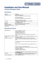
SW#13 - #16: Current Limit
These four switches control the current-limit set-
tings for the amplier. When all four switches are
in the UP posistion (default), the amplier’s output
current is limited to 60A. The current-limit can be
lowered in 4A increments by setting one or more
of the current limit switches in the DOWN position.
Refer to Figure 5.2 for all available current-limit
switch settings.
NOTE: If all four current-limit DIP switches are set
in the DOWN position, the amplier will be placed
in Standby/Stop mode. To return the amplier
to operational conditions, set at least one of the
current-limit DIP switches in the UP position.
5.2 Internal Jumpers and Settings
The 7228 amplier contains two circuit boards
with jumpers that can be used to alter the amplier
operation from the factory defaults. The Universal
Front-End Board (or UFEB) allows you to select
the compensation network for use in Controlled-
Current operation, congure the amplier to oper-
ate with a xed gain instead of the default variable
gain, insert a 50-kHz low-pass lter, congure the
amplier to enter Standby on startup instead of
entering Run mode (default), and congure the
amplier to enter Standby when an Overload fault
condition occurs. The Interconnect Board allows
selection of two always-on modes of operation for
the amplier’s multi-speed cooling fans.
The UFEB and Interconnect boards can be ac-
cessed by removing the amplier top cover. To
remove the amplier top cover, complete the steps
detailed in the following section.
ON = DIP Switch UP OFF = DIP Switch DOWN
SW#13 SW#14 SW#15 SW#16
Current
Limit
ON ON ON ON 60A
ON ON ON OFF 56A
ON ON OFF ON 52A
ON ON OFF OFF 48A
ON OFF ON ON 44A
ON OFF ON OFF 40A
ON OFF OFF ON 36A
ON OFF OFF OFF 32A
OFF ON ON ON 28A
OFF ON ON OFF 24A
OFF ON OFF ON 20A
OFF ON OFF OFF 16A
OFF OFF ON ON 12A
OFF OFF ON OFF 8A
OFF OFF OFF ON 4A
OFF OFF OFF OFF FAULT

97-8004188_08-31-2020
Information subject to change
19
7228 OPERATOR’S MANUAL – SECTION 5
2. Use the T-15 Torx wrench to remove the eight
(8) Torx screws, as shown in Figure 5.3.
3. Lift the cover straight up to remove and set
aside.
4. To replace the top cover, slide the cover in to
place on the amplier and replace the eight
screws.
Refer to Figure 5.4 for UFEB and Interconnect
board locations.
Refer to Figure 5.5 for UFEB and Interconnect
board jumper locations.
Figure 5.4 – UFEB and Interconnect Board Locations
Figure 5.3 – Removing the Amplier Top Cover
Uninsulated terminals with AC mains
potential are exposed when the top
cover is removed. Do not proceed until
the amplier has been turned o and the
AC Mains has been disconnected.
DANGER
After turning the amplier o, let the unit
sit for 3-5 minutes before removing the
top cover. This will allow the electrical
charge in the power supply capacitors to
discharge.
CAUTION
5.2.1 Amplier Top Cover Removal
Tool Required
T-15 Torx wrench
Procedure
1. Remove power from the amplier and discon-
nect any load from the amplier outputs. Wait a
minimum of three minutes to allow the ampli-
er’s capacitors to discharge.

Information subject to change
97-8004188_08-31-2020
7228 OPERATOR’S MANUAL – SECTION 5
20
Figure 5.5 – UFEB and Interconnect Board Jumper Locations
5.2.2 Jumper Settings on the Universal
Front-End Board
Compensation Network
When the 7228 amplier is used in Controlled-
Current mode, the current control loop is tuned
with an RC network. The factory default network
(CC1) provides 75k ohm resistance and 47 nF
capacitance. If this default network is not adequate
for your application and load, CC2 can be used to
install a custom RC network.
To change the compensation network, locate the
Compensation Network jumper (see Figure 5.5).
When pins 1 and 2 are jumpered (factory default),
network CC1 is enabled (75k ohm and 47 nF). To
select network CC2, place the shunt on the jumper
across pins 2 and 3.
Remove the shunt from the jumper to disable both
CC1 and CC2 networks. A small feedback capaci-
tor remains in the circuit to provide stability when
operating into an 8-ohm load. For more information
on Controlled-Current operation and installing a
custom RC network, see the “Applications” sec-
tion of this manual.
Enable/Stop on Powerup
The 7228 amplier will power-up to Run Mode
when a shunt is placed across pins 1 and 2 on the
Enable/Stop jumper (default setting). See Figure
5.5. To cause the 7228 amplier to enter Standby
(Stop Mode)
on power-up, place the shunt across
pins 2 and 3.
Fixed or Variable Gain
The 7228 amplier ships with an enabled Gain
Control knob, which is located on the amplier
front panel. To disable the Variable Gain control
and set for a Fixed Gain,
locate the Gain Control
Bypass jumper and place a shunt across the two
pins
at that location. See Figure 5.5.
Standby on Overload
The 7228’s IOC (Input/Output Comparator) Distor-
tion Alert circuit continuously compares the wave-
forms observed at the amplier input and output.
When a distortion between the two waveforms
of more than 0.5% occurs, the IOC circuit will
activate, and the Overload LED will light, but the
amplier will continue to operate. To congure the
7228 to move to Standby (Fault mode) when the
IOC circuit is activated, locate the Overload Latch
(see Figure 5.5) and place a shunt across the two
pins of the jumper.
Low Pass Filter Enable
The Low Pass Filter function inserts a 50 kHz (3-
dB down) low-pass lter at the amplier input to
/