Page is loading ...

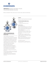
NEOTECHA SAPRO SAMPLING DEVICES
MAINTENANCE AND REPAIR INSTRUCTIONS
Wafer body bayonet adaptor
Wafer body bottle adaptor
Flanged body bayonet adaptor
Flanged body bottle adaptor
Sapro piston syringe
1 SAPRO SAMPLING DEVICES
Thank you for purchasing Neotecha sampling
equipment. These products incorporate the
latest in design and mated technology and
require little maintenance when applied and
cared for correctly.
Before undertaking any maintenance work on
Neotecha Sapro sampling devices the following
instructions should be read and understood
thoroughly. Any questions about these
instructions should be directed to Neotecha or
any authorized distributor.
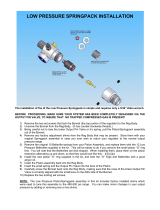
2 OPERATION
Details of the installation and operating
procedures will be found in a separate
publication: Maintenance and Installation
Instructions VCIOM-01977 and VCIOM-01978.
3 SAFETY
Prior to any disassembly, ensure that the unit
has been thoroughly cleaned. In every case,
protective equipment such as gloves, eye
protection etc., should be used when operating,
cleaning or maintaining the system. Attention
must be given to any national or company
regulations regarding dangerous media.
Environmental protection regulations may vary
according to the country or industry involved
and must be strictly observed.
Emerson.com/FinalControl © 2017 Emerson. All Rights Reserved. VCIOM-01984-EN 15/09
Before installation these instructions must be fully read and understood

2
8
9
6
C
B
NEOTECHA SAPRO SAMPLING DEVICES
MAINTENANCE AND REPAIR INSTRUCTIONS
5 CLEANING THE SYRINGE
After each use of the Sapro syringe, the unit
should be cleaned by thoroughly rinsing with an
appropriate cleaning fluid as follows:
1. Press the operating lever (8) against
thecylinder cage (9) and lock into position
by moving with the locking lever (6) from
position B and to position C.
2. Immerse the tip of the nozzle into a jar
containing the cleaning fluid.
3. Pull and push the piston rod repeatedly until
the syringe cylinder is clean.
4 ROUTINE INSPECTION
Sapro sampling valves and syringes are
precision engineered devices and need to
be kept clean and well maintained to ensure
perfect operation. The Sapro units should be
inspected periodically to ensure that seals are
not leaking, as follows:
a. Valve seat
Excessive moisture on the head of the safety
plug may indicate a leaking valve seat.
(Refertoreplacement instruction further on).
b. Spindle seal
Remove the yellow screwed plastic plug at
theleak detection port on the Sapro valve body.
Excessive moisture at this point may indicate
a leaking spindle seal. (Refer to replacement
instructions further on).
c. Syringe nozzle seal
When a sample has been drawn into the
syringe, examine the nozzle seal area and
the O-ring and piston seals on the cylinder.
Any leakage indicates the need to replace
the relevant seals. (Refer to replacement
instruction further on).
Cleaning the syringe

3
9
5
4a 4
6
7
2/3
a
b
10
11
12
13
14
6 SAPRO SYRINGE: MAINTENANCE
6.1 Syringe disassembly
Disassembly of the syringe unit for cleaning,
sterilization or replacement of components,
isundertaken as follows (see Fig. 1).
1. Unscrew the cage end cap (13) and remove
the cylinder assembly (10, 11, 12, 13 and 14)
from the syringe cage (9).
2. Unscrew the grip (14) and remove the cage
end cap (13).
3. Push the piston assembly (11) out of the
cylinder (12) in the direction of arrow (a), thus
pushing off the cylinder base (10) from the
cylinder. The direction of removal is important
to prevent damage to the piston seals.
4. Clean all disassembled parts and replace
asnecessary.
CAUTION
Reassemble the syringe by reversing the above
procedure, ensuring that the piston is inserted
into the cylinder in the direction of arrow (b).
6.2 Replacement of syringe nozzle seal
If the nozzle seal is leaking, it should be
replaced by implementing the following
procedure.
6.3 Seal removal (see Fig. 2)
1. With the syringe cap removed, loosen
thetwo set screws (6).
2. Unscrew the nozzle (5) from the syringe
head (7).
3. Ensure that the spacer (4) and washer (4a)
are removed from the nozzle.
4. Place the nozzle on a firm surface. Place
tool No. 1 on top of the nozzle and tap with
a mallet until the nozzle seal assembly
(2 and 3) falls out of the nozzle (see Fig. 3).
NEOTECHA SAPRO SAMPLING DEVICES
MAINTENANCE AND REPAIR INSTRUCTIONS
Figure 1
Figure 2
6.4 Seal replacement
1. Place the nozzle (5) in tool No. 4, asshown
(see Fig. 4).
2. Apply a little silicone oil to the replacement
nozzle seal assembly (2 and 3) and insert it
into the nozzle cavity.
3. Insert tool No. 3 into the nozzle and place
tool No. 2 over tool No. 3, as shown.
4. Tap tool No. 2 with a mallet until the nozzle
seal assembly is correctly located within
thenozzle.
5. Replace the spacer (4) and washer (4a) over
the syringe spindle as shown in Fig. 2.
6. Replace the nozzle assembly over the
syringe spindle and screw into position.
7. Secure the nozzle by tightening set
screws(6).
Figure 3
Figure 4
Nozzle tool
No. 1
Nozzle tool
No. 2
Nozzle tool
No. 3
Nozzle tool
No. 4

4
NEOTECHA SAPRO SAMPLING DEVICES
MAINTENANCE AND REPAIR INSTRUCTIONS
Figure 5
Figure 6
Figure 7
Figure 8
2-pin wrench
7 VALVE SEAT REPLACEMENT
A. Bottle adaptor models
1 Wafer body design (see Fig. 5 and Fig. 6)
You will need: repair kit - SV-Set 1 and tool
kit - SV-W2.
1.1 Take the Sapro valve from the pipe line.
1.2 Loosen the socket head screw (1d) and
remove the safety claw (1c).
1.3 Unscrew and remove bottle adaptor (5a).
1.4 Loosen the set screw (1a).
1.5 Using the 2-pin wrench (provided in tool
kit SV-W2), unscrew the retaining ring (5),
toreveal the valve seat assembly O-ring
(3a), soft seal (3) and valve seat (4).
1.6 Clean the bottle adaptor, valve seat and
retaining ring.
1.7 Replace the O-ring (3a) and seat seal (3)
with new parts from the repair kit SV-Set 1.
2 Flanged body design (see Fig. 7 and Fig. 8)
You will need: repair kit - SV-Set 1 and tool
kit - SV-W2.
2.1 Take the Sapro valve from the pipeline.
2.2 Loosen the three set screws (5a) and
withdraw the bottle adaptor assembly.
2.3 Remove the four socket head screws (1a)
and withdraw the retaining flange (5) to
reveal the valve seat assembly O-ring (3a),
soft seal (3) and valve seat holder (4).
2.4 Clean the bottle adaptor, retaining flange
and valve seat.
2.5 Replace the O-rings (3a, 5d) and seat
seal (3) with new parts from the seal kit
SV-Set1.
2.6 Reassemble by reversing the above
procedure.

5
NEOTECHA SAPRO SAMPLING DEVICES
MAINTENANCE AND REPAIR INSTRUCTIONS
B. Bayonet adaptor models
3 Wafer body design (See Fig. 9 and Fig. 10)
You will need: repair kit - SV-Set 1 and tool
kit - SV-W1.
3.1 Take the Sapro from the pipeline.
3.2 Loosen the set screws (1a) and unscrew
the bayonet adaptor assembly (5) to reveal
the valve seat assembly O-ring (3a), seat
seal (3) and valve seat (4).
3.3 Clean the bayonet adaptor assembly, valve
body recess and valve seat.
3.4 Replace the O-ring (3a) and seat seal (3)
with new parts from the seal kit SV-Set 1.
3.5 Reassemble by reversing the above
procedure.
4 Flanged body design (see Fig. 11 and Fig. 12)
You will need: repair kit - SV-Set 1 and tool
kit - SV-W1.
4.1 Take the Sapro from the pipeline.
4.2 Remove the four socket head screws
(1a) and withdraw the bayonet adaptor
assembly (5) to reveal the valve seat
assembly O-ring (3a), seat seal (3) and
valveseat (4).
4.3 Clean the bayonet adaptor assembly,
valvebody recess and valve seat.
4.4 Replace the O-ring (3a) and seat seal (3)
with new parts from the seal kit SV-Set 1.
4.5 Reassemble by reversing the above
procedure.
Figure 9 Figure 10
Figure 11
Figure 12

6
9a
9b
10b
10a
9
8
8a
11c
9a
11c
9
8
8a
NEOTECHA SAPRO SAMPLING DEVICES
MAINTENANCE AND REPAIR INSTRUCTIONS
Figure 13 Figure 14
Lever shown in
open position
Lever shown in
closed position
Spring tension device
assembly
8 SPINDLE SEAL REPLACEMENT
A. Bonnet disassembly
If excessive moisture is found on examination of
the leak detection port (see earlier) this may be
due to wear of the spindle seal. Replacement
of spindle seals should be undertaken by
implementing the following procedure.
1. Identify the model number of the Sapro
valve under consideration. The model
number of a Sapro valve is given on a metal
tag attached to the exterior of the valve
bonnet.
2. Referring to Tables 1 and 3, identify
theappropriate repair kit and tool kit
required for the subject Sapro valve.
3. Remove the Sapro valve from the pipeline.
NOTES
For bottle adaptor units with handlever only
(seeFig.13)
a. Unscrew the handlever (10a).
b. Slide off the protective (10b).
c. Remove adjustment screw (9a) and lock nut (9b).
CAUTION
The bonnet (9) is under spring tension. Follow
these instructions carefully.
4. Remove two opposing socket head screws
(8) replacing them with the two threaded
rods from the spring tension device from
tool kit SV-W3.
5. Place the two-hole plates over the threaded
rods followed by the washers and secure
with wing nuts as shown in Fig. 13.1/14.1.
6. Remove the remaining two socket head
screws.
7. Gradually loosen the wing nuts until the
spring tension in the bonnet is completely
relieved and then remove the threaded rods.
8. Remove bonnet (9) and gasket (8a) from
thevalve body.
9. On bayonet adaptor models only: remove
and replace the X-ring seal (9a) (see Fig.14).
10. Remove the spring (11c) from the spindle.
11. Clamp the end of the spindle assembly in a
soft jawed vice and pull the body away from
the spindle assembly.
12. Separate all parts of the spindle assembly
as shown in Fig. 15 and identify replacement
components from the appropriate repair kit.
Figure 13.1 Figure 14.1

7
10
11
11a
11c
11b
7
7a + b
7c
7d
6a
6
2
10b
10a
11
10
7
a
7
7c
7d
6a
6
2
NEOTECHA SAPRO SAMPLING DEVICES
MAINTENANCE AND REPAIR INSTRUCTIONS
Figure 15
Sapro valve spindle seal types
Type A Type B
1 Spindle seal assembly types A and B
1.1 Introduce valve spindle (2) into the Sapro
body until it rests on the valve seat.
1.2 Position the spindle seal (6) over the
spindle and push down using the spindle
seal drive tool included in tool kit SV-W3.
Gently tap the drive tool with a mallet until
the spindle seal locates at the bottom
ofthe cavity.
1.3 Position the other spindle assembly
components, in order, on the spindle,
asindicated in Fig. 15 A and B, replacing
theparts contained in the appropriate
repair kit.
1.4 Proceed with bonnet assembly as
described in the next section.
B. Seal assembly
NOTE
It is recommended that all soft seal components be
replaced at the same time.
• Referring to Tables 1 and 3, identify the repair kit,
spindle seal type and tool kit required for the subject
Sapro valve.
• Secure Sapro valve body upright in a vice. Take care
not to damage PFA sealing faces.
• Apply a little silicone oil to all the commencing
assembly.
• Refer to the assembly instructions below for
therelevant spindle seal type A or B (see Table 1).

8
9e
9a
9b
10b
10c
10a
11
11c
9
7a
8a
10
11a
8
11b
NEOTECHA SAPRO SAMPLING DEVICES
MAINTENANCE AND REPAIR INSTRUCTIONS
Figure 16
C. Bonnet re-assembly
1 Bayonet adaptor units only (spindle seal
typeB) (see Fig. 16)
1.1 Position gasket (8a) on valve body.
1.2 Screw spring support (10) onto the spindle
until finger tight, then back off by a quarter
turn.
1.3 Position the coil spring (11) over the spring
support.
1.4 Position the bonnet onto the valve body
over the coil spring and screw the two
threaded rods, from the spring tension
device in tool kit SV-W3, into opposing
holes in the valve body.
1.5 Place the two-hole plate over the threaded
rods, followed by the washers and tighten
the bonnet onto the valve by means of
thewing nuts.
1.6 Screw two socket head screws (8) into
the two remaining bonnet/body holes and
tighten.
1.7 Remove the spring tension device and
replace with two socket head screws (8).
Tighten all four screws to ensure full
compression of the coil spring.
1.8 Screw the position indicator (10b) lightly
onto the cap head screw (10a) through the
top of the bonnet, ensuring that it is finally
flush with the bonnet.
2 Bottle adaptor units only (spindle seal type A)
(see Fig. 17 and Fig. 18)
2.1 Position the gasket (8a) on the valve body.
2.2 Screw the spring support (11a) onto
thespindle until contact is made with
thelantern ring (7a).
NOTE
Ensure that the handlever has a lateral play of
minimum 7 mm and maximum 20 mm (refertoFig.17).
If lateral play requires adjustment:
a. Remove handlever and bonnet, as previously
described.
b. Loosen the securing screw (11b) to free the spring
support from the spindle.
c. Rotate the spring support a quarter turn counter
clockwise and re-tighten securing screw.
d. Rotate spindle assembly until the securing screw
is again aligned with the leak detection port.
e. Repeat assembly from instruction (2.7).
Figure 18
Closed
Figure 17
2.3 Screw the tie rod (10) into the spring
support until hand tight; then turn the tie
rod counter clockwise until the hole in the
tie rod is aligned with the next hole in the
spring support.
2.4 Position the locating screw (11c) in the
spring support hole which is aligned with
the non-countersunk side of the tie rod
hole (see Fig. 19).
2.5 Fix the spring support to the spindle by
means of the securing screw (11b) in the
hole opposite the locating screw.
2.6 Rotate the spindle assembly until the
securing screw is aligned with the leak
detection port in the valve body. (This port
has a yellow plastic blanking plug).
2.7 Place the coil spring (11) over the spring
support (11a).
2.8 Position the bonnet over the coil spring
ensuring that the locating screw (11c)
aligns with the key way in the bonnet.
2.9 Applying hand pressure on the bonnet
to compress the coil spring, secure the
bonnet to the valve body using the cap
head screws (8).
2.10 Slide protective sleeve (10b) over bonnet.
2.11 Locate the roller sleeve (10c) onto the
handlever and screw the handlever (10a/b)
into the tie rod (through the bonnet).
Figure 19
2.12 When lateral play is satisfactory, remove
the handlever and roller sleeve (10a/b/c).
2.13 Slide the protective sleeve (10b) into
position over the bonnet.
2.14 Re-fit the roller sleeve to the handlever
and the handlever to the tie rod
(throughthe bonnet).
2.15 Position the locking pin (9e) through the
bonnet. Try to operate the handlever
counter clockwise and check that the
spindle does not move off the valve seat.
2.16 Screw the set screw (9a) with hexagon nut
(9b) into the bonnet.

9
NEOTECHA SAPRO SAMPLING DEVICES
MAINTENANCE AND REPAIR INSTRUCTIONS
TABLE 1 - REPAIR KITS FOR SAPRO VALVE SEATS AND SPINDLE SEALS
Ref. nr. Description Sapro model nr. Spindle seal type
Kit contents
Part Nr.
SV-SET1 Repair kit seat seal on all Sapro sampling valves All N/A Soft seal 3
O-ring 3a
Set screw 1a
O-ring 5d
SV-SET9 Repair kit bottle adaptor seal All valves with bottle
adaptor
O-ring 5b
SV-SET10 Repair kit soft parts TFM stem lip seal SV..........S.. TFM stem seal Sealing sleeve 6
Size range DN 25 (NPS 1) to DN 100 (NPS 4) O-ring set 6a
PTFE/FKM seal ring 7a
Gasket 8a
O-ring 7b
SV-SET11 Repair kit soft parts TFM stem lip seal and Belleville set SV..........S.. TFM stem seal Sealing sleeve 6
Size range DN 25 (NPS 1) to DN 100 (NPS 4) O-ring set 6a
PTFE/FKM seal ring 7a
Gasket 8a
O-ring 7b
Belleville set 7c
Spacer 7d
Compression sleeve 7
SV-SET12 Repair kit spindle seal SV..........A.. Welded bellow seal Guide ring 7a
Size range DN 25 (NPS 1) to DN 100 (NPS 4) O-ring 7b
O-ring 7c
Gasket 8a
TABLE 2 - REPAIR KITS FOR SAPRO PISTON SYRINGES
Ref. nr. Description Syringe size
Contents
Part Nr.
SK-SET1 Maintenance of nozzle seal on Sapro piston syringe All Sealing sleeve 2
Pressure ring 3
SK-SET2 Maintenance of soft seals on Sapro piston syringes 20 ml X-ring 17
O-ring 18
O-ring 24a
SK-SET3 Maintenance of soft seals on Sapro piston syringes 50 ml and 100 ml X-ring 17
O-ring 18
O-ring 24a
SK-SET4 Maintenance of soft seals on Sapro piston syringes 250 ml X-ring 17
O-ring 18
O-ring 24a
SK-SET5 Replacement of piston head on Sapro piston syringes 20 ml Piston head 21a
SK-SET6 Replacement of piston head on Sapro piston syringes 50 ml and 100 ml Piston head 21a
SK-SET7 Replacement of piston head on Sapro piston syringes 250 ml Piston head 21a
Stroke adjustment
The degree of opening of the sampling valve
van be adjusted to the users requirements.
1. Loosen the lock nut (9b) and back off
theset screw (9a).
2. Remove the locking pin.
3. Operate the handlever to open the valve to
the required extent.
4. With the handlever held in this position,
screw down the set screw (9a) as far as
possible and release the handlever.
5. Tighten the hexagon nut (9b) to lock
theposition of the set screw.
6. Replace the locking pin (9e).

10
TABLE 3 - TOOL KITS FOR SAPRO VALVES AND PISTON SYRINGES
Ref. nr. Description Contents
SV-SETW1 Replacement of seat seal on all flanged Sapro valves and on wafer type Sapro’s with
bayonet adaptor
Metric hex key 3 mm
Metric hex key 5 mm
SV-SETW2 Replacement of seat seal on wafer type Sapro valves with bottle adaptor Metric hex key 3 mm
2-pin wrench
SV-SETW3 Replacement of spindle seals on all Sapro valves Metric hex key 3 mm
Metric hex key 4 mm
Metric hex key 5 mm
Spindle seal drive tool
Spring tension device
- 2 hole plate
- 2x threaded rods
- 2 wing nuts
- 2 washers
SK-SETW1 Replacement of nozzle seal on all Sapro piston syringes Metric hex key 3 mm
Metric hex key 4 mm
Nozzle tool nr. 1
Nozzle tool nr. 2
Nozzle tool nr. 3
Nozzle tool nr. 4
Neither Emerson, Emerson Automation Solutions, nor any of their affiliated entities assumes responsibility for the selection, use or maintenance of any product.
Responsibility for proper selection, use, and maintenance of any product remains solely with the purchaser and end user.
Neotecha is a mark owned by one of the companies in the Emerson Automation Solutions business unit of Emerson Electric Co. Emerson Automation Solutions, Emerson
and the Emerson logo are trademarks and service marks of Emerson Electric Co. All other marks are the property of their respective owners.
The contents of this publication are presented for informational purposes only, and while every effort has been made to ensure their accuracy, they are not to be
construed as warranties or guarantees, express or implied, regarding the products or services described herein or their use or applicability. All sales are governed by
our terms and conditions, which are available upon request. We reserve the right to modify or improve the designs or specifications of such products at any time without
notice.
Emerson.com/FinalControl
NEOTECHA SAPRO SAMPLING DEVICES
MAINTENANCE AND REPAIR INSTRUCTIONS
/