Page is loading ...

Installation Instructions for Catalog Series 92PLC
and 92PLC-DF AdaptaBeacon
®
Signals
DescriptionDescription
DescriptionDescription
Description
The Catalog Series 92PLC(*)-N5 and 92PLC-DF(*)-N5
AdaptaBeacon signals are UL and cUL Listed, general pur-
pose visual signaling appliances suitable for indoor or out-
door (weatherproof) installation. The 92PLC(*)-N5 series
signals are 120V single flash strobes and the 92PLC-DF(*)-
N5 series signals are 120V double flash strobes. They are
specifically designed for PLC compatibility and for flash-
ing from either a PLC or an external relay.
The 92-LST strobe tube is rated by the manufacturer at 11
joules and 1.1 million peak candela. The 92-ST strobe tube
is rated by the manufacturer at 14 joules and 1.4 million
peak candela.
The AdaptaBeacon signals utilize a standard base that al-
lows direct surface mounting, mounting on a 4" (102mm)
octagon box or mounting on 1/2" (13mm) NPT conduit.
The strobe is electrically isolated to prevent false flashes.
The unit also installs easily without having to add drop
resistors to the PLC output card.
For replacement strobe tubes and lenses, see "Replace-
ment Parts."
PLC Compatibility
The electrical input load requirements for PLC compatible
signaling devices are listed in Table 1. Signaling devices
may be directly connected to output cards that meet these
input load requirements.
SpecificationsSpecifications
SpecificationsSpecifications
Specifications
Strobe Tube
Catalog Number Ratings Life**
92PLC(*)-N5 120V AC 5,000 Hours
92PLC-DF(*)-N5 50/60 Hz 3,000 Hours
0.1 Amps
*Select color of lens by adding one of the
following letters to the cat. no.: A-amber, B-blue,
C-clear, G-green, M-magenta or R-red.
**Calculated strobe tube life at operating power
to 75% efficiency.
WARNING
To prevent electrical shock, ensure that power is
disconnected before installing the signal.
CAUTION
To prevent leakage, use care when disassembling
the signal to prevent tearing of weatherproof
gaskets. Should a lens or other component resist
removal due to adhesion to a gasket,
do not force
apart by hand.
Carefully separate the components
by prying them apart with a thin blade screwdriver.
Table 1. PLC Compatibility
Operating Maximum off state Continuous on Surge (inrush/duration)
Cat. No. voltage* leakage current (mA) current (mA) (A/ms**)
92PLC( )-N5 120V AC 5 100 20/0.075
92PLC-DF( )-N5 120V AC 5 100 20/0.075
*All AC volts at 60 Hz **Amps/milliseconds
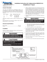
1. Remove the screw in the clamp ring and remove the
ring (Figure 1).
2. Lift the lens off of the signal base, remove the strobe
tube support plate and pull the wire leads out of the
conduit entrance hole in the base. Exercise care so as
to not tear the gaskets that are permanently attached
to the lens and signal base.
3. Mount the base using one of the following methods.
InstallationInstallation
InstallationInstallation
Installation
Install in accordance with the latest edition of the Na-
tional Electrical Code and applicable local codes.
P-047550-1760 ISSUE 6 © 2003
CAUTION
To prevent leakage when mounting outdoors, the
signal must be conduit mounted with the lens
facing directly up.
NOTE: For indoor installation, the signal may be direct
surface mounted, mouted on a 4" (102mm)
octagon box, or mounted on 1/2" (13mm) NPT
conduit. For outdoor (weatherproof)
installation, the signal must be conduit
mounted with the lens facing directly up.
a. Direct Surface Mounting (indoor only)
Remove the (2) knockouts for mounting screws
from the bottom of the signal base.
Route the field wiring from a 120V 50/60 Hz power
source through the conduit entrance hole in the
base.
Cheshire, CT 06410 203-699-3300 (Ph)
203-699-3365 (Cust. Serv. Fax)
203-699-3078 (Tech. Serv. Fax)

P-047550-1760 ISSUE 6
Cleaning
Strobe Tube Replacement
Refer to "Replacement Parts" for the required strobe tube.
1. Lift the lens off of the signal base being careful not to
tear the gaskets permanently affixed to the lens.
To prevent leakage, use care when disassembling
the signal to prevent tearing of the weatherproof
gaskets.
CAUTION
To prevent damage to the lens,
do not
use abrasive
materials or cleaners.
CAUTION
Clean the signal lens periodically with a soft cloth or
sponge using water or a mild detergent solution to main-
tain optimum light visibility. Ensure that the lens is com-
pletely dry before replacing.
To prevent damage to the external strobe tube wire
and strobe tube, handle the strobe tube
only
by the
base.
CAUTION
To prevent electrical shock, disconnect power and
allow five minutes for stored energy to dissipate
before diassembling the signal.
WARNING
Fasten the base to the surface using (2) #10 wood
screws (not supplied) or other suitable hardware
through the knockout holes in the base.
b. Mounting on a 4" (102mm) Octagon Box
(indoor only)
Remove the (2) knockouts for mounting screws
from the bottom of the signal base.
Route the field wiring from a 120V 50/60 Hz power
source through the conduit entrance hole in the
base.
Fasten the base to the octagon box (not supplied)
using the screws supplied with the box through
the knockout holes in the base.
c. Mounting on 1/2" (13mm) NPT Conduit
(indoor or outdoor)
Route the field wiring from a 120V 50/60 Hz power
source through the conduit and then through the
conduit entrance hole in the base.
Install the base on the conduit.
4. Connect the field wiring to the signal wire leads using
wire nuts (not supplied). Polarity is not important.
Connect the green ground wire leads using wire nuts
(not supplied). Place the connected wires inside the
base and reassemble the signal on the base.
5. Turn on power and verify that the signal operates
properly.
MaintenanceMaintenance
MaintenanceMaintenance
Maintenance
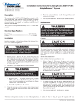
2. Grasp the base of the strobe tube and pull firmly, or
carefully pry between the strobe tube base and the
socket to remove the tube from the socket. Install
the new strobe tube by aligning the key on the strobe
tube base with the slot in the socket and then pressing
the strobe tube base onto the socket. Reassemble the
signal.
3. Turn on the power and verify that the strobe operates.

P-047550-1760 ISSUE 6
Figure 1. Mounting
Figure 2. Replacing the Strobe Tube
Replacement Parts
Replacement parts are available from your local Edwards distributor
AdaptaBeacon Model Component Catalog Number
92PLC(*)-N5 Strobe tube, Xenon 92-LST
92PLC-DF(*)-N5 Strobe tube, Xenon 92-ST
92PLC Series Lens V93-L(*)
*Specify color of lens by adding one of the following letters to the catalog number: A-amber,
B-blue, C-clear, G-green, M-magenta or R-red.
/