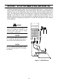
ESAB 300 AC/DC ARCMASTER® Inverter Arc Welder User manual
- Category
- Welding System
- Type
- User manual

400
V
1
50
60
Hz
INVERTER
Operating Manual
ARCMASTER
®
Version No: 1 Issue Date: April 17, 2006 Manual No.: 0-4904
Operating Features:
INVERTER ARC WELDER
300 AC/DC
Art # A-07238

WE APPRECIATE YOUR BUSINESS!
Congratulations on your new Thermal Arc product. We are proud
to have you as our customer and will strive to provide you with
the best service and reliability in the industry. This product is backed
by our extensive warranty and world-wide service network. To
locate your nearest distributor or service agency call
1-800-752-7621, or visit us on the web at www.thermalarc.com.
This Operating Manual has been designed to instruct you on the
correct use and operation of your Thermal Arc product. Your
satisfaction with this product and its safe operation is our ultimate
concern. Therefore please take the time to read the entire manual,
especially the Safety Precautions. They will help you to avoid
potential hazards that may exist when working with this product.
YOU ARE IN GOOD COMPANY!
The Brand of Choice for Contractors and Fabricators Worldwide.
Thermal Arc is a Global Brand of Arc Welding Products for
Thermadyne Industries Inc. We manufacture and supply to major
welding industry sectors worldwide including; Manufacturing,
Construction, Mining, Automotive, Aerospace, Engineering, Rural
and DIY/Hobbyist.
We distinguish ourselves from our competition through market-
leading, dependable products that have stood the test of time. We
pride ourselves on technical innovation, competitive prices,
excellent delivery, superior customer service and technical support,
together with excellence in sales and marketing expertise.
Above all, we are committed to develop technologically advanced
products to achieve a safer working environment within the welding
industry.

WARNINGS
Read and understand this entire Manual and your employer’s safety practices before installing,
operating, or servicing the equipment.
While the information contained in this Manual represents the Manufacturer's best judgement,
the Manufacturer assumes no liability for its use.
ArcMaster 300 AC/DC Inverter Arc Welder
Instruction Manual Number 0-4904 for:
Part Number 10-3098
Published by:
Thermadyne Industries Inc.
82 Benning Street
West Lebanon, New Hampshire, USA 03784
(603) 298-5711
www.thermalarc.com
Copyright 2006 by
Thermadyne Industries Inc.
All rights reserved.
Reproduction of this work, in whole or in part, without written permission of the publisher
is prohibited.
The publisher does not assume and hereby disclaims any liability to any party for any
loss or damage caused by any error or omission in this Manual, whether such error
results from negligence, accident, or any other cause.
Publication Date: April 17, 2006
Record the following information for Warranty purposes:
Where Purchased: ___________________________________
Purchase Date: ___________________________________
Equipment Serial #: ___________________________________

TABLE OF CONTENTS
SECTION 1:
SAFETY INSTRUCTIONS AND WARNINGS ................................................................................... 1
1.01 Arc Welding Hazards.............................................................................................................................. 1
1.02 Principal Safety Standards ..................................................................................................................... 4
1.03 Precautions de Securite en Soudage à l’Arc ........................................................................................... 5
1.04 Dangers Relatifs au Soudage à l’Arc ...................................................................................................... 5
1.05 Principales Normes de Securite ............................................................................................................. 8
1.06 Declaration of Conformity ...................................................................................................................... 9
SYMBOL LEGEND ...................................................................................................................... 11
SECTION 2:
INTRODUCTION AND DESCRIPTION .......................................................................................... 12
2.01 Description........................................................................................................................................... 12
2.02 Functional Block Diagram .................................................................................................................... 13
2.03 Transporting Methods.......................................................................................................................... 13
SECTION 3:
INSTALLATION RECOMMENDATIONS
3.01 Environment......................................................................................................................................... 14
3.02 Location............................................................................................................................................... 14
3.03 Electrical Input Connections................................................................................................................. 14
3.04 Electrical Input Requirements .............................................................................................................. 15
3.05 Input Power ......................................................................................................................................... 16
3.06 High Frequency Introduction................................................................................................................ 16
3.07 High Frequency Interference ................................................................................................................ 17
3.08 Specifications....................................................................................................................................... 18
3.09 Duty Cycle............................................................................................................................................ 19
SECTION 4:
OPERATOR CONTROLS
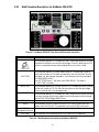
4.01 ArcMaster 300 AC/DC Controls............................................................................................................ 20
4.02 Weld Process Selection for ArcMaster 300 AC/DC............................................................................... 22
4.03 Weld Parameter Descriptions for ArcMaster 300 AC/DC ...................................................................... 23
4.04 Weld Parameters for ArcMaster 300 AC/DC......................................................................................... 25
4.05 Power Source Features........................................................................................................................ 26
SECTION 5:
SET-UP FOR SMAW (STICK) AND GTAW (TIG).............................................................................. 28
SECTION 6:
SEQUENCE OF OPERATION
6.01 Stick Welding....................................................................................................................................... 30
6.02 AC or DC HF TIG Welding..................................................................................................................... 30
6.03 Slope Mode Sequence.......................................................................................................................... 31
6.04 Slope Mode with Repeat Sequence...................................................................................................... 31
6.05 Pulse Controls...................................................................................................................................... 32
6.06 Save-Load Operation............................................................................................................................ 33

TABLE OF CONTENTS
SECTION 7:
BASIC TIG WELDING GUIDE
7.01 Explanation of “Fluttery Arc” when AC TIG Welding on Aluminum........................................................34
7.02 Electrode Polarity..................................................................................................................................35
7.03 Tungsten Electrode Current Ranges......................................................................................................35
7.04 Tungsten Electrode Types.....................................................................................................................35
7.05 Guide for Selecting Filler Wire Diameter................................................................................................36
7.06 Shielding Gas Selection ........................................................................................................................36
7.07 TIG Welding Parameters for Low Carbon & Low Alloy Steel Pipe .........................................................36
7.08 Welding Parameters for Aluminum.......................................................................................................37
7.09 Welding Parameters for Steel ...............................................................................................................37
SECTION 8:
BASIC ARC WELDING GUIDE
8.01 Electrode Polarity..................................................................................................................................38
8.02 Effects of Stick Welding Various Materials............................................................................................38
SECTION 9:
ROUTINE MAINTENANCE .......................................................................................................40
SECTION 10:
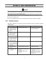
BASIC TROUBLESHOOTING
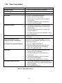
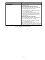
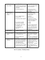
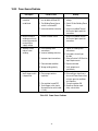
10.01 TIG Welding Problems........................................................................................................................41
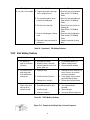
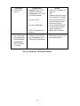
10.02 Stick Welding Problems......................................................................................................................43
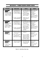
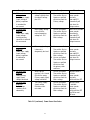
10.03 Power Source Problems .....................................................................................................................45
SECTION 11:
VOLTAGE REDUCTION DEVICE (VRD)
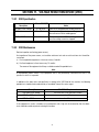
11.01 VRD Specification...............................................................................................................................47
11.02 VRD Maintenance ...............................................................................................................................47
11.03 Switching VRD ON/OFF.......................................................................................................................48
SECTION 12:
POWER SOURCE ERROR CODES ..............................................................................................50
APPENDIX A – INTERCONNECT DIAGRAM ..........................................................................................51
APPENDIX B – ARCMASTER 300 AC/DC ACCESSORIES...........................................................................55
LIMITED WARRANTY AND SCHEDULE
GLOBAL CUSTOMER SERVICE CONTRACT INFORMATION .................................................... Inside Rear Cover
Page is loading ...

1
ARCMASTER 300 AC/DC
7. Use fully insulated electrode holders. Never dip holder in water to
cool it or lay it down on the ground or the work surface. Do not
touch holders connected to two welding machines at the same
time or touch other people with the holder or electrode.
8. Do not use worn, damaged, undersized, or poorly spliced cables.
9. Do not wrap cables around your body.
10. Ground the workpiece to a good electrical (earth) ground.
11. Do not touch electrode while in contact with the work (ground)
circuit.
12. Use only well-maintained equipment. Repair or replace damaged
parts at once.
13. In confined spaces or damp locations, do not use a welder with
AC output unless it is equipped with a voltage reducer. Use
equipment with DC output.
14. Wear a safety harness to prevent falling if working above floor
level.
15. Keep all panels and covers securely in place.
WARNING
ARC RAYS can burn eyes and skin; NOISE can damage
hearing. Arc rays from the welding process produce
intense heat and strong ultraviolet rays that can burn
eyes and skin. Noise from some processes can damage
hearing.
1. Wear a welding helmet fitted with a proper shade of filter (see
ANSI Z49.1 listed in Safety Standards) to protect your face and
eyes when welding or watching.
2. Wear approved safety glasses. Side shields recommended.
1.01 Arc Welding Hazards
WARNING
ELECTRIC SHOCK can kill.
Touching live electrical parts can cause fatal shocks or
severe burns. The electrode and work circuit is electrically
live whenever the output is on. The input power circuit
and machine internal circuits are also live when power
is on. In semiautomatic or automatic wire welding, the
wire, wire reel, drive roll housing, and all metal parts
touching the welding wire are electrically live. Incorrectly
installed or improperly grounded equipment is a hazard.
1. Do not touch live electrical parts.
2. Wear dry, hole-free insulating gloves and body protection.
3. Insulate yourself from work and ground using dry insulating mats
or covers.
4. Disconnect input power or stop engine before installing or
servicing this equipment. Lock input power disconnect switch
open, or remove line fuses so power cannot be turned on
accidentally.
5. Properly install and ground this equipment according to its Owner’s
Manual and national, state, and local codes.
6. Turn off all equipment when not in use. Disconnect power to
equipment if it will be left unattended or out of service.
SECTION 1. SAFETY INSTRUCTIONS AND WARNINGS
!
WARNING
PROTECT YOURSELF AND OTHERS FROM POSSIBLE SERIOUS INJURY OR DEATH. KEEP CHILDREN AWAY. PACEMAKER WEARERS KEEP
AWAY UNTIL CONSULTING YOUR DOCTOR. DO NOT LOSE THESE INSTRUCTIONS. READ OPERATING/INSTRUCTION MANUAL BEFORE
INSTALLING, OPERATING OR SERVICING THIS EQUIPMENT.
Welding products and welding processes can cause serious injury or death, or damage to other equipment or property, if the operator does not
strictly observe all safety rules and take precautionary actions.
Safe practices have developed from past experience in the use of welding and cutting. These practices must be learned through study and
training before using this equipment. Some of these practices apply to equipment connected to power lines; other practices apply to engine
driven equipment. Anyone not having extensive training in welding and cutting practices should not attempt to weld.
Safe practices are outlined in the American National Standard Z49.1 entitled:
SAFETY IN WELDING AND CUTTING. This publication and other
guides to what you should learn before operating this equipment are listed at the end of these safety precautions. HAVE ALL INSTALLATION,
OPERATION, MAINTENANCE, AND REPAIR WORK PERFORMED ONLY BY QUALIFIED PEOPLE.

2
ARCMASTER 300 AC/DC
3. Use protective screens or barriers to protect others from flash
and glare; warn others not to watch the arc.
4. Wear protective clothing made from durable, flame-resistant
material (wool and leather) and foot protection.
5. Use approved ear plugs or ear muffs if noise level is high.
WARNING
FUMES AND GASES can be hazardous to your health.
Welding produces fumes and gases. Breathing these
fumes and gases can be hazardous to your health.
1. Keep your head out of the fumes. Do not breath the fumes.
2. If inside, ventilate the area and/or use exhaust at the arc to remove
welding fumes and gases.
3. If ventilation is poor, use an approved air-supplied respirator.
4. Read the Material Safety Data Sheets (MSDSs) and the
manufacturer’s instruction for metals, consumables, coatings, and
cleaners.
5. Work in a confined space only if it is well ventilated, or while
wearing an air-supplied respirator. Shielding gases used for
welding can displace air causing injury or death. Be sure the
breathing air is safe.
6. Do not weld in locations near degreasing, cleaning, or spraying
operations. The heat and rays of the arc can react with vapors to
form highly toxic and irritating gases.
7. Do not weld on coated metals, such as galvanized, lead, or
cadmium plated steel, unless the coating is removed from the
weld area, the area is well ventilated, and if necessary, while
wearing an air-supplied respirator. The coatings and any metals
containing these elements can give off toxic fumes if welded.
WARNING
WELDING can cause fire or explosion.
Sparks and spatter fly off from the welding arc. The flying
sparks and hot metal, weld spatter, hot workpiece, and
hot equipment can cause fires and burns. Accidental
contact of electrode or welding wire to metal objects
can cause sparks, overheating, or fire.
1. Protect yourself and others from flying sparks and hot metal.
2. Do not weld where flying sparks can strike flammable material.
3. Remove all flammables within 35 ft (10.7 m) of the welding arc.
If this is not possible, tightly cover them with approved covers.
4. Be alert that welding sparks and hot materials from welding can
easily go through small cracks and openings to adjacent areas.
5. Watch for fire, and keep a fire extinguisher nearby.
6. Be aware that welding on a ceiling, floor, bulkhead, or partition
can cause fire on the hidden side.
7. Do not weld on closed containers such as tanks or drums.
8. Connect work cable to the work as close to the welding area as
practical to prevent welding current from traveling long, possibly
unknown paths and causing electric shock and fire hazards.
9. Do not use welder to thaw frozen pipes.
10. Remove stick electrode from holder or cut off welding wire at
contact tip when not in use.
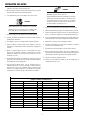
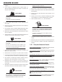
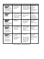
Welding or cutting Electrode Size Filter Welding or cutting Electrode Size Filter
Torch soldering 2 Gas metal-arc
Torch brazing 3 or 4 Non-ferrous base metal All 11
Oxygen Cutting Ferrous base metal All 12
Light Under 1 in., 25 mm 3 or 4 Gas tungsten arc welding All 12
Medium 1 to 6 in., 25-150 mm 4 or 5 (TIG) All 12
Heavy Over 6 in., 150 mm 5 or 6 Atomic hydrogen welding All 12
Gas welding Carbon arc welding All 12
Light Under 1/8 in., 3 mm 4 or 5 Plasma arc welding
Medium 1/8 to 1/2 in., 3-12 mm 5 or 6 Carbon arc air gouging
Heavy Over 1/2 in., 12 mm 6 or 8 Light 12
Shielded metal-arc Under 5/32 in., 4 mm 10 Heavy 14
5/32 to 1/4 in., 12 Plasma arc cutting
Over 1/4 in., 6.4 mm 14 Light Under 300 Amp 9
Medium 300 to 400 Amp 12
Heavy Over 400 Amp 14
Eye protection filter shade selector for welding or cutting
(goggles or helmet), from AWS A6.2-73.

3
ARCMASTER 300 AC/DC
WARNING
FLYING SPARKS AND HOT METAL can cause injury.
Chipping and grinding cause flying metal. As welds cool,
they can throw off slag.
1. Wear approved face shield or safety goggles. Side shields
recommended.
2. Wear proper body protection to protect skin.
WARNING
CYLINDERS can explode if damaged.
Shielding gas cylinders contain gas under high pressure.
If damaged, a cylinder can explode. Since gas cylinders
are normally part of the welding process, be sure to treat
them carefully.
1. Protect compressed gas cylinders from excessive heat, mechanical
shocks, and arcs.
2. Install and secure cylinders in an upright position by chaining
them to a stationary support or equipment cylinder rack to prevent
falling or tipping.
3. Keep cylinders away from any welding or other electrical circuits.
4. Never allow a welding electrode to touch any cylinder.
5. Use only correct shielding gas cylinders, regulators, hoses, and
fittings designed for the specific application; maintain them and
associated parts in good condition.
6. Turn face away from valve outlet when opening cylinder valve.
7. Keep protective cap in place over valve except when cylinder is in
use or connected for use.
8. Read and follow instructions on compressed gas cylinders,
associated equipment, and CGA publication P-1 listed in Safety
Standards.
!
WARNING
Engines can be dangerous.
WARNING
ENGINE EXHAUST GASES can kill.
Engines produce harmful exhaust gases.
1. Use equipment outside in open, well-ventilated areas.
2. If used in a closed area, vent engine exhaust outside and away
from any building air intakes.
WARNING
ENGINE FUEL can cause fire or explosion.
Engine fuel is highly flammable.
1. Stop engine before checking or adding fuel.
2. Do not add fuel while smoking or if unit is near any sparks or
open flames.
3. Allow engine to cool before fueling. If possible, check and add
fuel to cold engine before beginning job.
4. Do not overfill tank — allow room for fuel to expand.
5. Do not spill fuel. If fuel is spilled, clean up before starting engine.
WARNING
MOVING PARTS can cause injury.
Moving parts, such as fans, rotors, and belts can cut fingers and hands
and catch loose clothing.
1. Keep all doors, panels, covers, and guards closed and
securely in place.
2. Stop engine before installing or connecting unit.
3. Have only qualified people remove guards or covers for
maintenance and troubleshooting as necessary.
4. To prevent accidental starting during servicing, disconnect
negative (-) battery cable from battery.
5. Keep hands, hair, loose clothing, and tools away from moving
parts.
6. Reinstall panels or guards and close doors when servicing
is finished and before starting engine.
WARNING
SPARKS can cause BATTERY GASES TO EXPLODE;
BATTERY ACID can burn eyes and skin.
Batteries contain acid and generate explosive gases.
1. Always wear a face shield when working on a battery.
2. Stop engine before disconnecting or connecting battery cables.
3. Do not allow tools to cause sparks when working on a battery.
4. Do not use welder to charge batteries or jump start vehicles.
5. Observe correct polarity (+ and –) on batteries.

4
ARCMASTER 300 AC/DC
WARNING
STEAM AND PRESSURIZED HOT COOLANT can burn
face, eyes, and skin.
The coolant in the radiator can be very hot and under
pressure.
1. Do not remove radiator cap when engine is hot. Allow engine to cool.
2. Wear gloves and put a rag over cap area when removing cap.
3. Allow pressure to escape before completely removing cap.
!
WARNING
This product, when used for welding or cutting, produces
fumes or gases which contain chemicals know to the
State of California to cause birth defects and, in some
cases, cancer. (California Health & Safety code Sec.
25249.5 et seq.)
NOTE
Considerations About Welding And The Effects of Low
Frequency Electric and Magnetic Fields
The following is a quotation from the General Conclusions Section of
the U.S. Congress, Office of Technology Assessment, Biological Effects
of Power Frequency Electric & Magnetic Fields - Background Paper,
OTA-BP-E-63 (Washington, DC: U.S. Government Printing Office, May
1989): “...there is now a very large volume of scientific findings based
on experiments at the cellular level and from studies with animals and
people which clearly establish that low frequency magnetic fields
interact with, and produce changes in, biological systems. While most
of this work is of very high quality, the results are complex. Current
scientific understanding does not yet allow us to interpret the evidence
in a single coherent framework. Even more frustrating, it does not yet
allow us to draw definite conclusions about questions of possible risk
or to offer clear science-based advice on strategies to minimize or
avoid potential risks.”
To reduce magnetic fields in the workplace, use the following
procedures:
1. Keep cables close together by twisting or taping them.
2. Arrange cables to one side and away from the operator.
3. Do not coil or drape cable around the body.
4. Keep welding power source and cables as far away from
body as practical.
ABOUT PACEMAKERS:
The above procedures are among those also normally
recommended for pacemaker wearers. Consult your
doctor for complete information.
1.02 Principal Safety Standards
Safety in Welding and Cutting, ANSI Standard Z49.1, from American
Welding Society, 550 N.W. LeJeune Rd., Miami, FL 33126.
Safety and Health Standards, OSHA 29 CFR 1910, from Superintendent
of Documents, U.S. Government Printing Office, Washington, D.C.
20402.
Recommended Safe Practices for the Preparation for Welding and
Cutting of Containers That Have Held Hazardous Substances, Ameri-
can Welding Society Standard AWS F4.1, from American Welding
Society, 550 N.W. LeJeune Rd., Miami, FL 33126.
National Electrical Code, NFPA Standard 70, from National Fire
Protection Association, Batterymarch Park, Quincy, MA 02269.
Safe Handling of Compressed Gases in Cylinders, CGA Pamphlet P-
1, from Compressed Gas Association, 1235 Jefferson Davis Highway,
Suite 501, Arlington, VA 22202.
Code for Safety in Welding and Cutting, CSA Standard W117.2, from
Canadian Standards Association, Standards Sales, 178 Rexdale
Boulevard, Rexdale, Ontario, Canada M9W 1R3.
Safe Practices for Occupation and Educational Eye and Face Protec-
tion, ANSI Standard Z87.1, from American National Standards Insti-
tute, 1430 Broadway, New York, NY 10018.
Cutting and Welding Processes, NFPA Standard 51B, from National
Fire Protection Association, Batterymarch Park, Quincy, MA 02269.
Page is loading ...
Page is loading ...
Page is loading ...

8
ARCMASTER 300 AC/DC
1. Utilisez l’équipement à l’extérieur dans des aires ouvertes et bien
ventilées.
2. Si vous utilisez ces équipements dans un endroit confiné, les
fumées d’échappement doivent être envoyées à l’extérieur, loin
des prises d’air du bâtiment.
AVERTISSEMENT
LE CARBURANT PEUR CAUSER UN INCENDIE OU UNE
EXPLOSION.
Le carburant est hautement inflammable.
1. Arrêtez le moteur avant de vérifier le niveau e carburant ou de
faire le plein.
2. Ne faites pas le plein en fumant ou proche d’une source d’étincelles
ou d’une flamme nue.
3. Si c’est possible, laissez le moteur refroidir avant de faire le plein
de carburant ou d’en vérifier le niveau au début du soudage.
4. Ne faites pas le plein de carburant à ras bord: prévoyez de l’espace
pour son expansion.
5. Faites attention de ne pas renverser de carburant. Nettoyez tout
carburant renversé avant de faire démarrer le moteur.
AVERTISSEMENT
DES PIECES EN MOUVEMENT PEUVENT CAUSER DES
BLESSURES.
Des pièces en mouvement, tels des ventilateurs, des
rotors et des courroies peuvent couper doigts et mains,
ou accrocher des vêtements amples.
1. Assurez-vous que les portes, les panneaux, les capots et les
protecteurs soient bien fermés.
2. Avant d’installer ou de connecter un système, arrêtez le moteur.
3. Seules des personnes qualifiées doivent démonter des protecteurs
ou des capots pour faire l’entretien ou le dépannage nécessaire.
4. Pour empêcher un démarrage accidentel pendant l’entretien,
débranchez le câble d’accumulateur à la borne négative.
5. N’approchez pas les mains ou les cheveux de pièces en
mouvement; elles peuvent aussi accrocher des vêtements amples
et des outils.
6. Réinstallez les capots ou les protecteurs et fermez les portes après
des travaux d’entretien et avant de faire démarrer le moteur.
AVERTISSEMENT
DES ETINCELLES PEUVENT FAIRE EXPLOSER UN
ACCUMULATEUR; L’ELECTROLYTE D’UN ACCUMU-
LATEUR PEUT BRULER LA PEAU ET LES YEUX.
Les accumulateurs contiennent de l’électrolyte acide et
dégagent des vapeurs explosives.
1. Portez toujours un écran facial en travaillant sur un accumu-lateur.
2. Arrêtez le moteur avant de connecter ou de déconnecter des câbles
d’accumulateur.
3. N’utilisez que des outils anti-étincelles pour travailler sur un
accumulateur.
4. N’utilisez pas une source de courant de soudage pour charger
un accumulateur ou survolter momentanément un véhicule.
5. Utilisez la polarité correcte (+ et –) de l’accumulateur.
AVERTISSEMENT
LA VAPEUR ET LE LIQUIDE DE REFROIDISSEMENT
BRULANT SOUS PRESSION PEUVENT BRULER LA
PEAU ET LES YEUX.
Le liquide de refroidissement d’un radiateur peut être
brûlant et sous pression.
1. N’ôtez pas le bouchon de radiateur tant que le moteur n’est pas
refroidi.
2. Mettez des gants et posez un torchon sur le bouchon pour l’ôter.
3. Laissez la pression s’échapper avant d’ôter complètement le
bouchon.
1.05 Principales Normes de Securite
Safety in Welding and Cutting, norme ANSI Z49.1, American Weld-
ing Society, 550 N.W. LeJeune Rd., Miami, FL 33128.
Safety and Health Standards, OSHA 29 CFR 1910, Superintendent of
Documents, U.S. Government Printing Office, Washington, D.C.
20402.
Recommended Safe Practices for the Preparation for Welding and
Cutting of Containers That Have Held Hazardous Substances, norme
AWS F4.1, American Welding Society, 550 N.W. LeJeune Rd., Miami,
FL 33128.
National Electrical Code, norme 70 NFPA, National Fire Protection
Association, Batterymarch Park, Quincy, MA 02269.
Safe Handling of Compressed Gases in Cylinders, document P-1,
Compressed Gas Association, 1235 Jefferson Davis Highway, Suite
501, Arlington, VA 22202.
Code for Safety in Welding and Cutting, norme CSA W117.2 Asso-
ciation canadienne de normalisation, Standards Sales, 276 Rexdale
Boulevard, Rexdale, Ontario, Canada M9W 1R3.
Safe Practices for Occupation and Educational Eye and Face Protec-
tion, norme ANSI Z87.1, American National Standards Institute, 1430
Broadway, New York, NY 10018.
Cutting and Welding Processes, norme 51B NFPA, National Fire Pro-
tection Association, Batterymarch Park, Quincy, MA 02269.

9
ARCMASTER 300 AC/DC
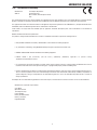
1.06 Declaration Of Conformity
Manufacturer: Thermadyne Corporation
Address: 82 Benning Street
West Lebanon, New Hampshire 03784
USA
The equipment described in this manual conforms to all applicable aspects and regulations of the ‘Low Voltage Directive’ (European Council
Directive 73/23/EEC as amended by Council Directive 93/68/EEC) and to the National legislation for the enforcement of this Directive.
The equipment described in this manual conforms to all applicable aspects and regulations of the “EMC Directive” (European Council Directive
89/336/EEC) and to the National legislation for the enforcement of this Directive.
Serial numbers are unique with each individual piece of equipment and details description, parts used to manufacture a unit and date of
manufacture.
National Standard and Technical Specifications
The product is designed and manufactured to a number of standards and technical requirements. Among them are:
• CSA (Canadian Standards Association) standard C22.2 number 60 for Arc welding equipment.
• UL (Underwriters Laboratory) rating 94VO flammability testing for all printed-circuit boards used.
• CENELEC EN50199 EMC Product Standard for Arc Welding Equipment.
• ISO/IEC 60974-1 (BS 638-PT10) (EN 60 974-1) (EN50192) (EN50078) applicable to plasma cutting
equipment and associated accessories.
• For environments with increased hazard of electrical shock, Power Supplies bearing the S mark conform to EN50192 when used in
conjunction with hand torches with exposed cutting tips, if equipped with properly installed standoff guides.
• Extensive product design verification is conducted at the manufacturing facility as part of the routine design and manufacturing process.
This is to ensure the product is safe, when used according to instructions in this manual and related industry standards, and performs as
specified. Rigorous testing is incorporated into the manufacturing process to ensure the manufactured product meets or exceeds all
design specifications.
Thermadyne has been manufacturing products for more than 30 years, and will continue to achieve excellence in our area of manufacture.
Manufacturers responsible representative:
Steve Ward
Operations Director
Thermadyne Europe
Europa Building
Chorley N Industrial Park
Chorley, Lancashire,
England PR6 7BX
Page is loading ...

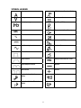
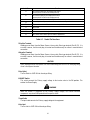
11
SYMBOL LEGEND
Amperage
STICK (Shielded Metal Arc SMAW)
Voltage
Pulse Current Function
Hertz (frequency)
Spot Time (GTAW)
SEC
Seconds
Remote Control (Panel/Remote)
%
Percent
Remote Function
DC (Direct Current)
Arc Control (SMAW)
AC (Alternating Current
Gas Post-Flow
Standard Function
Gas Pre-Flow
Slope Function
VRD
Voltage Reduction Device Circuit
Slope W/Repeat Function
Negative
Spot Function
Positive
Impulse Starting (High Frequency
GTAW)
Gas Input
Touch Start (Lift Start TIG circuit
GTAW)
Gas Output

12
SECTION 2. INTRODUCTION AND DESCRIPTION
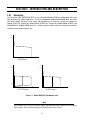
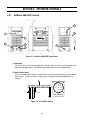
2.01 Description
The Thermal Arc
TM
ARC MASTER 300 AC/DC is a self contained three-phase AC/DC arc welding power source with
Constant Current (CC) output characteristics. This unit is equipped with a Digital Volt/Amperage Meter, gas control
valve, built in Sloper and Pulser, lift arc starter, and high-frequency arc starter for use with Gas Tungsten Arc
Welding (GTAW), Gas Tungsten Arc Welding-Pulsed (GTAW-P) Gas Tungsten Arc Welding-Sloped (GTAW-S), and
Shielded Metal Arc Welding (SMAW) processes. The power source is totally enclosed in an impact resistant, flame
retardant and non-conductive plastic case.
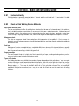
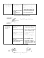
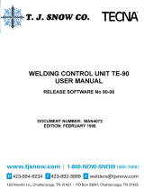
300A5A (A)
(V)
OCV
STICK Process
300A25A
(A)
(V)
OCV
10V
300A (A)
(V)
OCV
5A
LIFT TIG Process HF TIG Process
Figure 2-1. Model 300 AC/DC Volt-Ampere curve
Note
Volt-Ampere curves show the maximum Voltage and Amperage output capabilities of the welding
power source. Curves of other settings will fall between the curves shown.

13
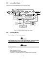
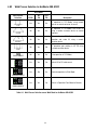
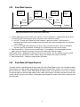
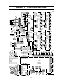
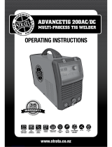
2.02 Functional Block Diagram
Figure 2 illustrates the functional block diagram of the 300 AC/DC-power supply.
Ma i n
Circuit
Switch
Filter
Input
Diode
Primary
Capacitor
DC Power
Voltage
Sensor
IGBT
Inverter
Thermal
Detector
To each control circuit
+/-15VDC +18VDC
+24VDC +5VDC
Troublel
Sensing
Circuit
Drive
Circuit
Torch Control
Connection
(CON1)
circuit
Current
Adjustment
Reference
Adjustment &
Mode select Switches
Panel Circuit Board
Sequence
Control
Themal
Sensor
Circuit
Ma i n
Transformer
(PCB14)
Output
Diodes
HF-UNIT
Control
Circuit
Stick Mode
VRD
Sensing
Circuit
Lift Tig Mode
Output Short
Sensing
Circuit
Coupling
High
Coil
Frequency
Unit
Fan Control
Circuit
Gas Control
Circuit
Fan
Solenoid
Hall Current
Transformer
(HCT1)
Output
Inductor
Thermal
Detector
+
-
+-
Input
Power
Secandary
DC Power
Voltage Sensor
To each control circuit
+/-12VDC +15VDC
Secondary
IGBT
Inverter
Drive
Circuit
Primary
Current
Sensor
Figure 2-2. 300 AC/DC Model Functional Block Diagram
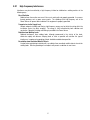
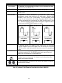
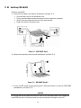
2.03 Transporting Methods
This unit is equipped with a handle for carrying purposes.
WARNING 1
ELECTRIC SHOCK can kill. DO NOT TOUCH live electrical parts. Disconnect input power
conductors from de-energized supply line before moving the welding power source.
WARNING 2
FALLING EQUIPMENT can cause serious personal injury and equipment damage.
Lift unit with handle on top of case.
Use handcart or similar device of adequate capacity.
If using a fork lift vehicle, place and secure unit on a proper skid before transporting.

14
SECTION 3. INSTALLATION RECOMMENDATIONS
3.01 Environment
The ArcMaster 300 AC/DC is designed for use in adverse environments.
Examples of environments with increased adverse conditions are:
a. In locations in which freedom of movement is restricted, so that the operator is forced to
perform the work in a cramped (kneeling, sitting or lying) position with physical contact with
conductive parts.
b. In locations which are fully or partially limited by conductive elements, and in which there is a
high risk of unavoidable or accidental contact by the operator.
c. In wet or damp hot locations where humidity or perspiration considerably reduces the skin
resistance of the human body and the insulation properties of accessories.
Environments with adverse conditions do not include places where electrically conductive parts are in
the near vicinity of the operator, which can cause increased hazard, have been insulated.
3.02 Location
Be sure to locate the welder according to the following guidelines:
•
In areas, free from moisture and dust.
•
Ambient temperature between 0 degrees C
to 40 degrees C.
•
In areas, free from oil, steam and
corrosive gases.
•
In areas, not subjected to abnormal
vibration or shock.
•
In areas, not exposed to direct
sunlight or rain.
•
Place at a distance of 12” (304.79mm) or
more from walls or similar boundaries that
could restrict natural airflow for cooling.
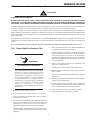
WARNING
Thermal Arc advises that this equipment be electrically connected by a qualified electrician.
3.03 Electrical Input Connections
WARNING
ELECTRIC SHOCK can kill; SIGNIFICANT DC VOLTAGE is present after removal of input power.
DO NOT TOUCH live electrical parts.
SHUT DOWN welding power source, disconnect input power employing lockout/tagging
procedures. Lockout/tagging procedures consist of padlocking line disconnect switch in open
position, removing fuses from fuse box, or shutting OFF and red-tagging circuit breaker or other
disconnecting device.

15
3.04 Electrical Input Requirements
Operate the welding power source from a single-phase 50/60 Hz, AC power supply. The input voltage
must match one of the electrical input voltages shown on the input data label on the unit nameplate.
Contact the local electric utility for information about the type of electrical service available, how proper
connections should be made, and any inspection required.
The line disconnect switch provides a safe and convenient means to completely remove all electrical
power from the welding power supply whenever necessary to inspect or service the unit.
Note
This unit is equipped with a three-conductor with earth power cable that is connected at the welding
power source end for single and three phase electrical input power.
Do not connect an input (BROWN or BLUE or RED) conductor to the ground terminal.
Do not connect the ground (YELLOW/GREEN) conductor to an input line terminal.
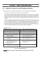
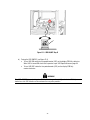
Refer to Figure 3:
1. Connect end of ground (YELLOW/GREEN) conductor to a suitable ground. Use a grounding method that
complies with all applicable electrical codes.
2. Connect ends of line 1 (BROWN) and line 2 (BLUE) and line 3 (RED) input conductors to a
de-energized line disconnect switch.
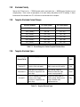
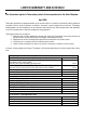
3. Use Table 3-1 and Table 3-2 as a guide to select line fuses for the disconnect switch.
Input Voltage Fuse Size
400V 60 Amps
Table 3-1. Electrical Input Connections
Note
Fuse size is based on not more than 200 percent of the rated input amperage of the welding
power source (Based on Article 630, National Electrical Code).
Figure 3-1. Electrical Input Connections

16
3.05 Input Power
Each unit incorporates an INRUSH circuit and input voltage sensing circuit. When the MAIN CIRCUIT
SWITCH is turned on, the inrush circuit provides a pre-charging of the input capacitors. SCR’s in the
Power Control Assembly (PCA) will turn on after the input capacitors have charged to full operating voltage
(after approximately 5 seconds).
Note
Note the available input power. Damage to the PCA could occur if 460VAC or higher is applied.
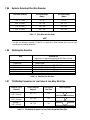
The following 400 Primary Current recommendations are required to obtain the maximum welding
current and duty cycle from this welding equipment:
Table 3-2. 400V Primary Current Circuit sizes to achieve maximum current
The ARCMASTER 300 AC/DC is designed for use with a generator as an input power source. Contact an
accredited Thermal Arc service agent for the proper sizing and set-up recommendations of a generator
power source system. As a general rule, depending on the type of generator used, the generator capacity
should be twice the maximum rating of the welder.
3.06 High Frequency Introduction
The importance of correct installation of high frequency welding equipment cannot be over-emphasized.
Interference due to high frequency initiated or stabilized arc is almost invariably traced to improper
installation. The following information is intended as a guide for personnel installing high frequency
welding machines.
Warning
Explosive
s
The high frequency section of this machine has an output similar to a radio transmitter. The
machine should NOT be used in the vicinity of blasting operations due to the danger of premature
firing.
Computers
It is also possible that operation close to computer installations may cause computer malfunction.
Current & Duty Cycle
Model
Primary Supply
Lead Size (Factory
Fitted)
Minimum Primary
Current Circuit Size
(Vin/Amps)
TIG STICK
400/28 300 @ 40% - ArcMaster
300 AC/DC
4mm sq / 4
minimum
400/40 300 @ 40%

17
3.07 High Frequency Interference
Interference may be transmitted by a high frequency initiated or stabilized arc welding machine in the
following ways:
Direct Radiation
Radiation from the machine can occur if the case is metal and is not properly grounded. It can occur
through apertures such as open access panels. The shielding of the high frequency unit in the
Power Source will prevent direct radiation if the equipment is properly grounded.
Transmission via the Supply Lead
Without adequate shielding and filtering, high frequency energy may be fed to the wiring within the
installation (mains) by direct coupling. The energy is then transmitted by both radiation and
conduction. Adequate shielding and filtering is provided in the Power Source.
Radiation from Welding Leads
Radiated interference from welding leads, although pronounced in the vicinity of the leads,
diminishes rapidly with distance. Keeping leads as short as possible will minimize this type of
interference. Looping and suspending of leads should be avoided where possible.
Re-radiation from Unearthed Metallic Objects
A major factor contributing to interference is re-radiation from unearthed metallic objects close to the
welding leads. Effective grounding of such objects will prevent re-radiation in most cases.

18
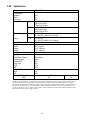
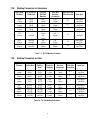
3.08 Specifications
Parameter 300 AC/DC
Rated Output
Amperes
Volts
Duty Cycle
300
22
30%
Duty Cycle TIG 300A / 22V @ 40%
250A / 20V @ 60%
180A / 18V @ 100%
STICK 300A / 32V @ 40%
250A / 30V @ 60%
180A / 28V @ 100%
Output Current TIG 5 – 300 (DC)
5 – 300 (AC) @ 60Hz, 50% Cleaning
Range STICK 5 – 300 (DC)
5 – 300 (AC) @ 60Hz, 50% Cleaning
Open Circuit Voltage 65V
Dimensions
Width
Height
Length
8.3” (210mm)
16.5” (420mm)
17.7” (450mm)
Weight 52.8 lb. 24 kg
Output @ Rated Load
Rated Input Voltage
Output Amperes
Output Volts
Duty Cycle
KVA
KW
Three-phase
300A
32V
40%
18.0
12.0
Output @ No Load
KVA
KW
0.5
0.13
Input Volts Single Phase
400V
Amperage Draw @ Rated Load
40
No Load Amps
1.6
Thermal Arc continuously strives to produce the best product possible and therefore reserves the right to change, improve or revise the
specifications or design of this or any product without prior notice. Such updates or changes do not entitle the buyer of equipment
previously sold or shipped to the corresponding changes, updates, improvements or replacement of such items. The values specified in
the table above are optimal values, your values may differ. Individual equipment may differ from the above specifications due to in
part, but not exclusively, to any one or more of the following; variations or changes in manufactured components, installation location
and conditions and local power grid supply conditions.

19
3.09 Duty Cycle
The duty cycle of a welding power source is the percentage of a ten (10) minute period that it can be
operated at a given output without causing overheating and damage to the unit. If the welding amperes
decrease, the duty cycle increases. If the welding amperes are increased beyond the rated output, the
duty cycle will decrease.
WARNING
Exceeding the duty cycle ratings will cause the thermal overload protection circuit to become
energized and shut down the output until the unit has cooled to normal operating temperature.
CAUTION
Continually exceeding the duty cycle ratings can cause damage to the welding power source
and will void the manufactures warranty.
NOTE
Due to variations that can occur in manufactured products, claimed performance, voltages,
ratings, all capacities, measurements, dimensions and weights quoted are approximate only.
Achievable capacities and ratings in use and operation will depend upon correct installation,
use, applications, maintenance and service.
Page is loading ...
Page is loading ...
Page is loading ...
Page is loading ...
Page is loading ...
Page is loading ...
Page is loading ...
Page is loading ...
Page is loading ...
Page is loading ...
Page is loading ...
Page is loading ...
Page is loading ...
Page is loading ...
Page is loading ...
Page is loading ...
Page is loading ...
Page is loading ...
Page is loading ...
Page is loading ...
Page is loading ...
Page is loading ...
Page is loading ...
Page is loading ...
Page is loading ...
Page is loading ...
Page is loading ...
Page is loading ...
Page is loading ...
Page is loading ...
Page is loading ...
Page is loading ...
Page is loading ...
Page is loading ...
Page is loading ...
Page is loading ...
Page is loading ...
Page is loading ...
Page is loading ...
Page is loading ...
Page is loading ...
-
 1
1
-
 2
2
-
 3
3
-
 4
4
-
 5
5
-
 6
6
-
 7
7
-
 8
8
-
 9
9
-
 10
10
-
 11
11
-
 12
12
-
 13
13
-
 14
14
-
 15
15
-
 16
16
-
 17
17
-
 18
18
-
 19
19
-
 20
20
-
 21
21
-
 22
22
-
 23
23
-
 24
24
-
 25
25
-
 26
26
-
 27
27
-
 28
28
-
 29
29
-
 30
30
-
 31
31
-
 32
32
-
 33
33
-
 34
34
-
 35
35
-
 36
36
-
 37
37
-
 38
38
-
 39
39
-
 40
40
-
 41
41
-
 42
42
-
 43
43
-
 44
44
-
 45
45
-
 46
46
-
 47
47
-
 48
48
-
 49
49
-
 50
50
-
 51
51
-
 52
52
-
 53
53
-
 54
54
-
 55
55
-
 56
56
-
 57
57
-
 58
58
-
 59
59
-
 60
60
-
 61
61
-
 62
62
-
 63
63
-
 64
64
-
 65
65
-
 66
66


ESAB 300 AC/DC ARCMASTER® Inverter Arc Welder User manual
- Category
- Welding System
- Type
- User manual
Ask a question and I''ll find the answer in the document
Finding information in a document is now easier with AI
Related papers
-
ESAB 300 AC/DC ARCMASTER® Inverter Arc Welder User manual
-
-
-
-
-
-
-
-
-
Other documents
-
Miller S-64M Owner's manual
-
Tyan Tomcat n3400B S2925 Important information
-
Unimig PK11086 User manual
-
 TECNA te-90 User manual
-
 Thermal Arc PORTAFEED VS 212 Operating instructions
-
Forney 435 AC-DC G Welder User manual
-
Cebora 241 TIG Star 250 AC-DC User manual
-
 Strata ADVANCETIG 200 Operating Instructions Manual
-
Crossfire DIGITIG 200 Owner's manual
-
 Tweco ARCMASTER 401S Operating instructions


