Page is loading ...

InstallatIon GuIde
1100X Wireless Receivers
Description
The 1100X Wireless Receiver is compatible with all DMP wireless devices. The receiver provides two-way, supervised
communication using 900 MHz frequency hopping-spread-spectrum technology. The receiver can be mounted up to
1,000 feet from the panel enclosure. The receiver provides up to 500 wireless zones. Refer to the panel installation
guide for number of available wireless zones.
Compatibility
• XR500SeriespanelsusingrmwareVersion113orhigher
• XR100 Series panels
• XR150/XR350/XR550Seriespanels
What is Included
The receiver includes the following items:
• OneModel1100XWirelessReceiver
• One4-wireHarness
• Hardwarepack
Compliance Instructions
ForapplicationsthatmustconformtoaNationalRecognizedTestingLaboratorycerticatedsystem,pleaseseethe
ListedComplianceSpecicationssectionattheendofthisguideforadditionalinstructions.
Installing the Wireless Receiver
Selecting a Location
Choose an optimum location to mount the receiver. The 1100X Wireless Receiver is typically mounted at a distance
not to exceed 1000 feet away from the panel enclosure. A location should be selected that is centrally located
between the 1100 Series transmitters used in the installation. Install the receiver away from large metal objects.
Mounting the receiver on or near metal surfaces impairs performance. Do not use shielded wire between the panel
andreceiver.Whenselectingthepropermountinglocationofatransmitter,refertotheLEDSurveyOperation
sectionofthespecicinstallationguideforthetransmitterbeinginstalled.
Tamper Switches
The 1100X is equipped with a case tamper and a wall tamper.
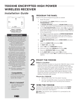
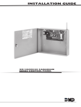
Mounting the Receiver
1. Remove the cover from the plastic housing by
squeezing both sides toward each other.
2. Secure the receiver to the wall in the desired
location installing the supplied shoulder
washers and screws in the mounting hole
locations as shown in Figure 1.
3.Snapthecoverbackontheunit.Thepanel
immediately recognizes the 1100X Receiver if
the panel is programmed with a house code.
U5
1
J5
1
RED
J4
1
PROG
PANEL
J3
1
RED
Power
RXD
TXD
Status
RF RXD
RF TXD
J4
1
U4
1
Q2
U7
J1
1
Mounting Hole
Locations
Squeeze to
Remove Cover
Squeeze to
Remove Cover
J4 Not Used
J3 Connects
To Panel
Mounting Screw
Shoulder Washer
Power
Panel Receive
Panel Transmit
Status
RF Receive
RF Transmit
LEDs
Tamper
Switch
Figure 1: Receiver PCB

Digital Monitoring Products 1100X Wireless Receiver Installation Guide
2
Wireless Bus Connection
The 1100X easily interfaces with the XR500/XR500FC and XR100/XR100FC Series panels using the on-board DMP
Wireless Bus connection (J22).
OnXR150/XR350/XR550Seriespanels,the1100Xinterfacesusingtheon-boardX-Busconnection(J13).
Note: The 1100X Wireless Receiver cannot operate if connected to the Keypad Bus.
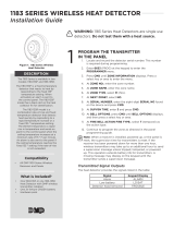
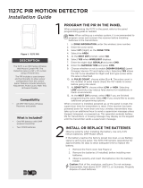
Harness Connection XR100/XR100FC/XR500/XR500FC panels
1.Installajumperacrosstheheaderpinsnexttotheletter“X”ontheXR100/XR100FC/XR500/XR500FCpanelJ23
header to enable on-board DMP Wireless operation.
2.Usingthesupplied4-wireharness,connectfromtheJ3headeronthe1100XWirelessReceivertotheXR100/
XR100FC/XR500/XR500FC panel J22 LX header.
3.Afterpower-up,brieyresetthepanelusingtheJ16jumpertoactivatezoneoperation.
4.InSystemOptions,programtheHouseCode(1-50).InZoneInformation,programthewirelesszones.
Figure 3: XR100/XR100FC or XR500/XR500FC DMP Wireless Bus Connection
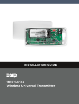
Harness Connection XR150/XR350/XR550 panels
1.ConnecttheJ3headeronthe1100XtotheXR150/XR350/XR550panelJ13X-BUSheader.
2.Afterpower-up,brieyresetthepanelusingtheJ16jumpertoactivatewirelesszoneoperation.
3.InSystemOptions,programtheHouseCode(1-50).InZoneInformation,programthewirelesszones.
Figure 4: XR150/XR350/XR550 DMP Wireless Bus Connection
U5
1
J5
1
RED
J4
1
PROG
PANEL
J3
1
RED
Power
RXD
TXD
Status
RF RXD
RF TXD
U8
1
J4
1
U4
1
U7
J1
1
AC
1234 5678 10 11 12 13 14 15 169
+B BELL GND SMK GNDRED YEL GRN BLKZ1Z2Z3AC –B GND G
K6 K7
Output 1Output 2
J10
J22
LX
Battery
Start
J23
J21
RS-232
Power
LED
J8
PROG
Out1 Out2
J2
XR100/XR100FC/XR500/XR500FC
Series Panel
R
L
X
Black
Green
Yellow
Red
Can be extended
up to 1000 feet
from the panel
Red
1100X
Receiver
J4 Not Used
XMT - Transmit LED
REC - Receive LED
Black
Green
Yellow
Red
Can be extended
up to 100 feet
from the panel
using 22 AWG
or 250 feet
using 18 AWG
XR150/XR350/XR550
Series Panel
Battery Start
Power
LED
U5
1
J5
1
RED
J4
1
PROG
PANEL
J3
1
RED
Power
RXD
TXD
Status
RF RXD
RF TXD
U8
1
J4
1
U4
1
U7
J1
1
1100X
Receiver
J4 Not Used
REC - Receive LED
XMT - Transmit LED

1100X Wireless Receiver Installation Guide Digital Monitoring Products
3
1100X Receiver Operation
The 1100X receiver automatically sends the panel house code to wireless transmitters when the unique transmitter serial
numberisprogrammedintothepanel.Thehousecodeidentiesthepanel,receiver,andtransmitterstoeachother.The
receiveronlylistensfortransmissionsusingthespeciedhousecodeand/orprogrammedtransmitterserialnumber.
Note: When setting up a wireless system, it is recommended to program zones and connect the receiver before
installing batteries in the transmitters.
Transmitters can be programmed for supervised operation. When programmed as supervised, the transmitter must
communicate with the receiver within the programmed number of minutes. If the transmitter fails to communicate, the
panel displays a missing condition.
Note: When a receiver is installed, powered up, or the panel is reset, the supervision time for transmitters is reset. If the
receiverhasbeenpowereddownformorethanonehour,wirelesstransmittersmaytakeuptoanadditionalhourtosend
a supervision message unless tripped, tampered, or powered up. This operation extends battery life for transmitters. A
missingmessagemaydisplayonthekeypaduntilthetransmittersendsasupervisionmessage.
When any wireless zone programming is changed in the panel, receiver zone programming is updated. At that point, all
wireless zones display as normal for approximately one minute, regardless of the actual state of the contact.
1100X LED Operation
Six LEDs display receiver operation and activity. Refer to the table below as required.
PCB LEDs Label Operation
Power
RXD
TXD
Status
RF RXD
RF TXD
POWER Steady green to indicate there is power to the receiver.
RXD Flashes yellow to indicate data is being received from the panel.
TXD Flashes green to indicate data is being sent to the panel.
STATUS Steadyredtoindicatememoryupload.Offwhenuploadiscomplete.
RF RXD Flashes yellow to indicate data is being received from a transmitter.
RF TXD Flashes green to indicate data is being sent to a transmitter.
Transmitter Survey LED Operation
DMP1100SeriestransmittersprovideTwo-way(transmitacknowledge)operation.Thisadvanceddataprotocolallowseach
transmittertoconrmthateachofitsmessages(alarm,checkin,tamper,lowbattery)arereceivedandacknowledged
bythe1100Seriesreceiver.TheconrmationisindicatedvisuallybyuseofanLEDoneachtransmitter.ThisSurveyLED
shouldbeusedduringinstallationtotesteachtransmitterforproperoperation.AfulldenitionoftheSurveyLEDfollows.
TheredLEDonan1100Seriestransmitterturnsonwhentheprocessorwakesuptosendamessage.Thenafteraseries
of communication steps are completed (successful or not),theLEDturnsoffwhentheprocessorgoesbacktosleep.99.9%
of the time the processor is asleep in normal operation. The following list summarizes various indications that can be
observedontheLEDandadenitionforeach.Notethisisforasinglemessage.Example,pressingandholdingthetamper
switch.
Single 1/16 second ash
•Processorwakesup
•Transmitterreceivesimmediatesynchronizationfromreceiver
•Transmittertransmits
•Transmitterreceivesimmediateacknowledgementfromreceiver
•Processorgoestosleep
Single Pulse greater than 1/16 second but shorter than 8 seconds
•Processorwakesup
•Transmitterreceivessynchronizationfromreceiver-possiblynotimmediate
•Transmittertransmits
•Transmitterreceivesacknowledgementfromreceiver-possiblynotimmediate
•Processorgoestosleep
Steady for 8 seconds
•Processorwakesup
•Transmitterneverreceivessynchronizationfromreceiver,ormightreceivesynchronization
•Transmittertransmitsifsynchronizationwasreceived
•Transmitterneverreceivesanyfurtherdatafromreceiver
•Processortimesoutandgoestosleep
Multiple short ashes
•Processorwakesup
•Transmitterreceivessynchronizationfromreceiver
•Transmittertransmits
•Transmitterreceivesdatafromreceiver,butnotavalidacknowledgement
•Processorbrieygoestosleep
•Entiresequenceisrepeated,eachshortashindicatesacycle

Digital Monitoring Products 1100X Wireless Receiver Installation Guide
4
Troubleshooting Using the Transmitter Survey LED
If a transmitter is unable to reliably communicate a message to the receiver, or is reported as missing, the Survey LED can
be used to help diagnose the issue. If the missing transmitter cannot be explained by obvious reasons such as a damaged
transmitter, failed battery, or changes in building construction; then the Survey LED should be used.
TousetheSurveyLEDoperationtohelpdiagnoseaeldissue,completethefollowingstepsonan1100Seriestransmitter.
Repeat the following sequence 5 times and write down the LED operation for each tamper switch action.
•Pressandholdthetamperswitch
•ObservetheLEDuntilitturnsoffforatleast5seconds
•Releasethetamperswitch
•ObservetheLEDuntilitturnsoffforatleast5seconds
You now have observed the LED 10 times. Based on the results you have recorded use the list below to assist in
troubleshooting.
LED turns on a single time for less than 1 second 8 to 10 times.
•Systemisworkingproperly
LED turns on for more than 1 second 3 to 9 times.
•Thetransmitterorreceiverneedstoberelocated
LED turns on for more than 1 second all 10 times.
•Thereceiverisnotturnedon,orisnotoperating
•Thetransmitterisnotprogrammedintothereceiver
•Thetransmitterorreceiverneedstoberelocated
LED ashes multiple times with a single tamper press or release 3 to 10 times.
•Thetransmitterorreceiverneedstoberelocated
LED never turns on.
•Thetransmitterbatteryisdead
•Thetamperswitchisbeingpressedorreleasedtooquickly
•Thetamperswitchorotherpartofthetransmitterisbroken
LED stays on constantly and is dim
•Thetransmitterbatteryisalmostdead
•Thetransmitterisbroken
General Wireless Troubleshooting
IfALLwirelessdevicesdonotoperate,refertothefollowingchecklist:
• Verifythereceiverisan1100XandthepanelisanXR500SerieswithrmwareVersion113orhigheroranXR100/
XR100FC/XR500FC,orXR150/XR350/XR550Seriespanel.
or
VerifytheXR100/XR100FC/XR500/XR500FCpanelJ23jumperisinthe“X”positionandthe4-wireJ3connectorfrom
the receiver is connected to J22 of the panel.
or
VerifytheJ3connectorfromthereceiverisconnectedtoJ13ontheXR150/XR350/XR550panel.
• BrieyresetpanelusingJ16jumpertoactivatewirelessoperationandwaitoneminutetotestwirelesszone(s).
• VerifytheHouseCode(1-50)isprogrammedinSystemOptions.
• Verifyappropriatezonenumbersareassignedaswirelesszones.
• VerifythatthepanelXMITandRECLEDsalternatelyashonandoffatarateof1/4secondeach.IftheLEDsareOn
steadyorOff,thepanelandreceiverarenotcommunicatingproperly.(SeeFigure3and4).
• Verifythe1100XLEDsoperatecorrectlyaslistedin1100XLEDOperation.
• Verifytransmittershavebatteriescorrectlyinserted.

1100X Wireless Receiver Installation Guide Digital Monitoring Products
5
Transmitter Supervision Time
For UL Listed installations, program the transmitter supervision time in panel zone programming as listed in the following
table.
Refer to the panel programming guide for complete wireless programming information.
UL Listing Listed Accessories
Supervision
Time
UL 1023 HouseholdBurglaryAlarmSystemUnitsAccessory 1100R Repeater
1101/1102/1103/1106Universal
Transmitters
1127W/1127C PIR Motion Detector
1135WirelessSounder
1142Two-ButtonHold-UpTransmitter
9060/9063WirelessKeypad
60
UL 636 HoldupAlarmUnitsandSystemsAccessory 1142Two-ButtonHold-UpTransmitter 60
UL 634 ConnectionsandSwitchesforusewithBurglarAlarm
Systems Accessory
1100R Repeater
1101/1102/1103/1106Universal
Transmitters
60
UL 639 IntrusionDetectionUnitsAccessory 1100R Repeater
1127W/1127C PIR Motion Detector
60
UL 365 PoliceStationConnectedBurglarAccessory 1100R Repeater
1103UniversalTransmitter
60
UL 609 LocalBurglarAlarmUnitsandSystemAccessory 1100R Repeater
1103UniversalTransmitter
60
UL 1076 ProprietaryBurglarAlarmUnitsAccessory 1100R Repeater
1103UniversalTransmitter
60
UL 1610 CentralStationBurglarAlarmUnitsAccessory 1100R Repeater
1103UniversalTransmitter
1135WirelessSounder
9060/9063WirelessKeypad
60
UL 268 Smoke-AutomaticFireDetectors 1100R Repeater
1161/1162ResidentialSmokeDetectors
1164WirelessSynchronizedSmoke
Detector
1165/1165H/1165HSCommercialSmoke
3
UL 521 Heat Detectors for Fire Protective Signaling Systems 1100R Repeater
1183-135F/1183-135RHeatDetector
3
UL 985 HouseholdFireWarningSystemAccessory 1100R Repeater
1135WirelessSounder
9060/9063WirelessKeypad
240
UL 864 FireProtectiveSignalingSystems 1103UniversalTransmitter
1100R Repeater
3
UL 2075 GasandVaporDetectorsandSensors 1184WirelessCarbonMonoxideDetector 240
FCC Information
ThisdevicecomplieswithPart15oftheFCCRules.Operationissubjecttothefollowingtwoconditions
(1) This device may not cause harmful interference, and
(2) this device must accept any interference received, including interference that may cause undesired operation.
Changesormodicationsmadebytheuserandnotexpresslyapprovedbythepartyresponsibleforcompliancecouldvoidthe
user’s authority to operate the equipment.
Note: This equipment has been tested and found to comply with the limits for a Class B digital device, pursuant to part 15 of the
FCC Rules. These limits are designed to provide reasonable protection against harmful interference in a residential installation.
This equipment generates, uses and can radiate radio frequency energy and, if not installed and used in accordance with the
instructions, may cause harmful interference to radio communications. However, there is no guarantee that interference will not
occur in a particular installation. If this equipment does cause harmful interference to radio or television reception, which can be
determined by turning the equipment off and on, the user is encouraged to try to correct the interference by one or more of the
following measures:
- Reorient or relocate the receiving antenna.
- Increase the separation between the equipment and receiver.
- Connect the equipment into an outlet on a circuit different from that to which the receiver is connected.
- Consultthedealeroranexperiencedradio/TVtechnicianforhelp.
Note: The 1100 Series wireless system is a two-way supervised wireless design compliant with FCC rules as they pertain to 900
MHz Spread Spectrum devices. In rare instances it has been observed that certain 900 MHz cordless telephones may occasionally
experienceaclickingsoundonthetelephonewhileinuse.Ifthisoccurs,itmayberesolvedbyselectingadifferentchannelon
the cordless telephone, or replacing the cordless phone with a different brand or model of 900 MHz telephone or other cordless
telephone.
To comply with RF exposure requirements, a minimum distance of 20cm must be maintained between the antenna and all persons.
Attention! Older Cordless Telephones
Yourwirelessalarmsystemiscomprisedofastate-of-the-arttwo-waysecurenetworkcreatedbysophisticatedtransmittersand
receivers. It is compliant with all FCC rules as they pertain to 900 MHz Spread Spectrum devices which require devices to share the same
frequencies. This creates a possibility of interference with other devices in your home.

800-641-4282
www.dmp.com 2500 North Partnership Boulevard
LT-0708 1.05 © 2015 Digital Monitoring Products, Inc.
15255
Ithasbeenreportedthatcertainolder900MHzcordlesstelephonesmayonrareoccasionsexperienceinterference(anaudibleclicking
sound)whileinuse.(Thismayalsooccurwithsome2.4GHzand5.8GHztelephonesasmanystilluse900MHzfrequencies).Ifthis
occurs on your cordless telephone, it may be resolved by selecting a different channel on your telephone. If your telephone does not
havethisselection,itcanalsoberesolvedbyreplacingyouroldcordlesstelephonewithaDECT6.0cordlesstelephone.
What is DECT 6.0?
DECT6.0(DigitalEnhancedCordlessTelecommunications)isthecurrentstandardforcordlesstelephones,anditprovidesseveralbenets
over900MHz,2.4GHzand5.8GHzsystems.
• NoMoreInterference-unlikeoldercordlesstechnology,DECT6.0telephonesarevirtuallyimmunetohouseholdinterference,
andviceversa.Ifyouhaveawirelesscomputernetworkinyourhome,DECT6.0won’tdisruptinternetuse.
• EncryptedPrivacy–DECT6.0hasalayerofsecuritythatoldercordlesstelephonesjustdon’thave.Asinformationandidentity
theftisontherise,DECTencryptionhelpskeepyourpersonalcommunicationssafe.
• CallQuality-Extrasecurityisn’tjustforsafety;itgivesyouclearercallswithoutcrossovertrafc.
• BatteryLife-ADECT6.0phonewilllastasmuchas30%longerthana5.8GHzphone.
More information can be found on DECT technology at www.DECT.org.
DECT6.0Cordlessphonescanbefoundatanymajorretailerincluding:Wal-Mart™,Target™,BestBuy™&RadioShack™.
Listed Compliance Specications
Commercial Fire
Transmitters must be programmed as supervised. Refer to the Transmitter Supervision Time table for the supervision
time.
Themaximumlineimpedanceofthe4-wirebusis16.2Ohmsfor1000feet.
The recommended wire gauge for panel to receiver connection is 22 AWG.
Afteralltransmittersareinposition,theWLSoptionofthepanel’sWalkTestmustbeoperatedandalltransmitters
programmedforFire(FI)orSupervisory(SV)mustshowthattheircheckinmessagewasreceived.Refertothepanel
programmingguideforTripCounterforDMPWirelesscheck-inTest(WLS)whichdescribesthatbothnumbersofthe
counter must match. If not and a failed wireless zone is displayed at END, decrease that transmitters range with the
receiverandperformtheWLSWalkTestagain.
Specications
OperatingVoltage 8.0to14VDC
CurrentDraw 46mA
RF Power Rating 27mW
FrequencyRange 905-924MHz
Dimensions
ReceiverHousing 4.65”Lx3.1”Wx1.4”H
Antennas 8.6”H
Color White
Housing Material Flame retardant ABS
Patents
U.S.PatentNo.7,239,236
Certications
ANSI/UL365 PoliceStationConnectedBurglar
ANSI/UL609 LocalBurglarAlarmUnitsandSystems
ANSI/UL634 ConnectionsandSwitchesforusewith
Burglar Alarm Systems Accessory
ANSI/UL636 HoldupAlarmUnitsandSystem
ANSI/UL639 IntrusionDetectionUnitsAccessory
ANSI/UL1023 HouseholdBurglarAlarmSystemUnits
ANSI/UL1076 ProprietaryBurglarAlarmUnits
ANSI/UL1610 CentralStationBurglarAlarmUnits
ANSI/UL864 FireProtectiveSignalingSystems
ANSI/UL985 HouseholdFireWarningSystem
California State Fire Marshal (CSFM)
FCC Part 15: CCK1100
NewYorkCity(FDNYCOA#6167)
IndustryCanada:5251A-PC0082
/