Page is loading ...

97091C (Rev. D - 10/99)
OVL-EBP * C , OVL-SBP * C , OVL-SEBP * F , OVL-ESBP * F
PAGE 1
Halsey Taylor Owners Manual
Non-Refrigerated Fountains
To assure you install this model easily and correctly,
PLEASE READ THESE SIMPLE INSTRUCTIONS BEFORE STARTING THE
INSTALLATION. CHECK YOUR INSTALLATION FOR COMPLIANCE WITH
PLUMBING, ELECTRICAL AND OTHER APPLICABLE CODES. After installation, leave
these instructions inside the fountain for future reference.
IMPORTANT
ALL SERVICE TO BE PERFORMED BY AN AUTHORIZED SERVICE PERSON
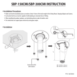
FIG. 1
TUBE IS
SECURED
IN POSITION
SIMPLY PUSH IN
TUBE TO ATTACH
PUSH IN COLLET
TO RELEASE TUBE
PUSHING TUBE IN BEFORE
PULLING IT OUT HELPS TO
RELEASE TUBE
FIG. 2
OPERATION OF QUICK CONNECT FITTINGS
OVL-EBP OVL-SBP OVL-SEBP OVL-ESBP
FIG. 3 FIG. 4
23
24 15
14
Regulator Mounting
Bracket
IMPORTANT! INSTALLER PLEASE NOTE.
THE GROUNDING OF ELECTRICAL EQUIPMENT SUCH AS TELEPHONE, COMPUTERS, ETC. TO WATER LINES
IS A COMMON PROCEDURE. THIS GROUNDING MAY BE IN THE BUILDING OR MAY OCCUR AWAY FROM THE
BUILDING. THIS GROUNDING CAN CAUSE ELECTRICAL FEEDBACK INTO A FOUNTAIN, CREATING AN ELEC-
TROLYSIS WHICH CAUSES A METALLIC TASTE OR AN INCREASE IN THE METAL CONTENT OF THE WATER.
THIS CONDITION IS AVOIDABLE BY USING THE PROPER MATERIALS AS INDICATED. ANY DRAIN FITTINGS
PROVIDED BY THE INSTALLER SHOULD BE MADE OF PLASTIC TO ELECTRICALLY ISOLATE THE FOUNTAIN
FROM THE BUILDING PLUMBING SYSTEM.
Installer
NOTE: WATER FLOW
DIRECTION
BUILDING WATER INLET
SERVICE STOP
(NOT FURNISHED)
1/4" O.D. TUBE
WATER INLET
TO COOLER
3/8" O.D. UNPLATED
COPPER TUBE CONNECT
COLD WATER SUPPLY

97091C (Rev. D - 10/99)
OVL-EBP * C , OVL-SBP * C , OVL-SEBP * F , OVL-ESBP * F
PAGE 2
OVL - EBP/SBP/SEBP/ESBP COOLER INSTALLATION
1. Wall should already be framed for the fountain using the rough-in dimensions shown
in Figs. 5,6,7, or 8. Shown dimensions pertain to installation location (framing must support
up to 150 lbs. weight for single fountain and 300 lbs. for dual fountains). These dimensions
are required for compliance with ANSI Standard A117.0.
2. Attach hanger bracket to wall as shown in Figs. 5,6,7, or 8 using 5/16" x 3/4" long bolts and
flat washers (not provided). Tighten securely.
3. Install back panel. Place the upper edge of the panel above hanger on the wall. Slide the
panel down until it engages the hanger. Be sure back panel is firmly engaged before
releasing it.
4. Install rough-in plumbing as shown in Figs. 5,6,7, or 8. Waste line should extend a
minimum of 2" (51mm) thru the back panel. Run supply water inlet line thru back panel.
Install a service stop (not provided). Turn on supply water and flush thoroughly.
5. Remove bottom access panel from fountain basin and save the screws. Install the fountain
to the back panel and wall using (4) 5/16 x 2 long lag bolts and washers (not provided)
thru holes in back panel. Tighten securely.
6. Cut waste tube to required length using plumbing hardware and trap (not provided) as a
guide. Install hardware and trap. Tighten securely.
7. Make water supply connections from service stop to the fountain strainer. Insert the
water inlet line into the inlet side of strainer until it reaches a positive stop - about 3/4"
(See Fig. 2). Turn on water supply and check for leaks. Newly installed water supply line
should be insulated after leak check is completed. DO NOT SOLDER TUBES INSERTED
INTO THE STRAINER AS DAMAGE TO THE O-RINGS MAY RESULT.
8. Check stream height from bubbler. Stream height is factory set at 45-50 PSI. If supply
pressure varies greatly from this, adjust the screw on regulator (item 14, on page 1).
Clockwise adjustment will raise stream height and counter-clockwise will lower stream
height. For best adjustment stream height should be approximately 1-1/2" (38mm) above
the bubbler guard. (See Figure 3)
9. Water Valve Mechanism - ADJUSTMENT PROCEDURE:
- Turn adjustment screw (Item 26, page 7) counter-clockwise until water flow from
bubbler starts
- Turn adjustment screw clockwise until water flow stops, then turn an additional
1/2 turn
10. Replace bottom access panel to fountain using the screws provided. Tighten securely.

97091C (Rev. D - 10/99)
OVL-EBP * C , OVL-SBP * C , OVL-SEBP * F , OVL-ESBP * F
PAGE 3
FIG. 5
LEGEND:
A = 1-1/4" O.D. Waste Tube (Trap And Elbow Not Provided)
B = 3/8" O.D. Unplated Copper Tube Connect (Water Inlet)
FINISHED FLOOR

97091C (Rev. D - 10/99)
OVL-EBP * C , OVL-SBP * C , OVL-SEBP * F , OVL-ESBP * F
PAGE 4
LEGEND:
A = 1-1/4" O.D. Waste Tube (Trap And Elbow Not Provided)
B = 3/8" O.D. Unplated Copper Tube Connect (Water Inlet)
FIG. 6
FINISHED FLOOR

97091C (Rev. D - 10/99)
OVL-EBP * C , OVL-SBP * C , OVL-SEBP * F , OVL-ESBP * F
PAGE 5
FIG. 7
LEGEND:
A = 1-1/4" O.D. Waste Tube (Trap And Elbow Not Provided)
B = 3/8" O.D. Unplated Copper Tube Connect (Water Inlet)
FINISHED FLOOR

97091C (Rev. D - 10/99)
OVL-EBP * C , OVL-SBP * C , OVL-SEBP * F , OVL-ESBP * F
PAGE 6
FIG. 8
LEGEND:
A = 1-1/4" O.D. Waste Tube (Trap And Elbow Not Provided)
B = 3/8" O.D. Unplated Copper Tube Connect (Water Inlet)
FINISHED FLOOR

97091C (Rev. D - 10/99)
OVL-EBP * C , OVL-SBP * C , OVL-SEBP * F , OVL-ESBP * F
PAGE 7
FIG. 10 FIG. 11
19
2
20
29
26
29
26
27
30
22 31
25Stream Height Adjustment
18
5
10
8
9
12
13
6
7
8
11
1See Fig. 11
21See Fig. 4
3, 4
16
17
See Fig. 10
FIG. 9
PUSH BAR MECHANISM REGULATOR MOUNTING MECHANISM

97091C (Rev. D - 10/99)
OVL-EBP * C , OVL-SBP * C , OVL-SEBP * F , OVL-ESBP * F
PAGE 8
DESCRIPTION
26990C
26988C
55836C
55991C
51546C
45396C
100322740560
160270508640
45400C
101570540560
51575C
110346208550
101637451550
161637308640
45398C
45683C
45682C
100023340560
161570808550
61314C
50986C
27006C
27342C
27000C
27344C
70861C
55840C
55839C
27002C
27338C
27004C
27340C
26992C
15005C
40045C
27008C
70856C
70854C
50198C
51468C
22646C
22635C
22797C
27885C
22799C
27887C
26958C
27889C
22795C
27891C
27084C
27089C
27090C
55996C
15008C
55994C
1
2
3
4
5
6
7
8
9
10
11
12
13
14
15
16
17
18
19
20
21
22
23
24
25
26
27
28
29
30
31
32
33
NS
NS
NS
NS
NS
PART NO.
Bottom Cover (OVL-S)
Bottom Cover (OVL-E)
Push Arm Actuator
Push Arm Actuator - AG
Bubbler
Bubbler - AG
Bubbler Gasket
Strainer Plate
Strainer Plate - AG
Drain Gasket
Packing Ring
Drain Nut
Friction Ring
Drain Plug
Drain Plug - AG
Waste Elbow (OVL-E)
Waste Elbow (OVL-S)
Waste Tube Gasket
Slip Nut
Regulator
Regulator Holder
Basin
Basin - AG
Basin Liner
Basin Liner - AG
Screw # 10-24 x 2
Top Plate - Actuator
Bottom Plate - Actuator
Arm w/Weldnuts (OVL-E)
Carrier Arm - AG (OVL-E)
Arm w/Weldnuts (OVL-S)
Carrier Arm - AG (OVL-S)
Regulator Mounting Bracket
Nut - Retaining
Nut Hex - UNPLTD
Reaction Bracket
Screw #10-24 x .38 PHMS
Rod - Pivot
Bushing Snap
Bumper - Reg. Valve Assy
Reg. Arm Assy
Arm - Reg. Adjust
Back Panel (OVL-EBP)
Back Panel (OVL-EBP) (AG)
Back Panel (OVL-SBP)
Back Panel (OVL-SBP) (AG)
Back Panel (OVL-SEBP)
Back Panel (OVL-SEBP) (AG)
Back Panel (OVL-ESBP)
Back Panel (OVL-ESBP) (AG)
Fountain Mounting Bracket
Back Panel Hanger Bracket (OVL-EBP/SBP)
Back Panel Hanger Bracket (OVL-SEBP/ESBP)
Strainer
Bubbler Nipple Assy
Tubing - Poly (Order in Feet)
ITEM NO.
PARTS LIST
FOR PARTS, CONTACT YOUR LOCAL DISTRIBUTOR OR CALL 1.800.323.0620
2222 CAMDEN COURT
OAK BROOK, IL 60523
630.574.3500
PRINTED IN U.S.A.
TROUBLE SHOOTING AND MAINTENANCE
Orifice Assy: Mineral deposits on orifice can cause water flow to spurt or
not regulate. Mineral deposits may be removed from the orifice with a
small round file or small diameter wire.
CAUTION: DO NOT file or cut orifice material.
Stream Regulator: If orifice is clean, regulate flow as in
STREAM HEIGHT ADJUSTMENT instructions on pg 2. If replacement
is necessary, see parts list for correct regulator part number.
Actuation of Quick Connect Water Fittings: Fountain is provided with
lead-free connectors which utilize an o-ring water seal. To remove
tubing from the fitting, relieve water pressure, push in on the gray collar
while pulling on the tubing.(see Fig.2) To insert tubing, push tube
straight into fitting until it reaches a positive stop, approximately 3/4".
CAUTION: Cleaning of Aztec Gold Models requires special care.
Outer surfaces must be cleaned with a mild detergent or mixture of
vinegar and water only, rinsed and wiped dry. Abrasive and acidic
cleaners may eventually damage the Aztec Gold finish.
32
SEE PUSH BAR MECHANISM
(ON PAGE 7)
SEE PUSH BAR MECHANISM
(ON PAGE 7)
SEE DETAIL
(ON PAGE 7)
SEE DETAIL
(ON PAGE 7)
32
33
33
/