Page is loading ...

INSTRUCTION MANUAL
Zero Air Generator
6/15
Copyright © 2015
Campbell Scientific, Inc.


Limited Warranty
“Products manufactured by CSI are warranted by CSI to be free from defects in
materials and workmanship under normal use and service for twelve months
from the date of shipment unless otherwise specified in the corresponding
product manual. (Product manuals are available for review online at
www.campbellsci.com.) Products not manufactured by CSI, but that are resold
by CSI, are warranted only to the limits extended by the original manufacturer.
Batteries, fine-wire thermocouples, desiccant, and other consumables have no
warranty. CSI’s obligation under this warranty is limited to repairing or
replacing (at CSI’s option) defective Products, which shall be the sole and
exclusive remedy under this warranty. The Customer assumes all costs of
removing, reinstalling, and shipping defective Products to CSI. CSI will return
such Products by surface carrier prepaid within the continental United States of
America. To all other locations, CSI will return such Products best way CIP
(port of entry) per Incoterms ® 2010. This warranty shall not apply to any
Products which have been subjected to modification, misuse, neglect, improper
service, accidents of nature, or shipping damage. This warranty is in lieu of all
other warranties, expressed or implied. The warranty for installation services
performed by CSI such as programming to customer specifications, electrical
connections to Products manufactured by CSI, and Product specific training, is
part of CSI's product warranty. CSI EXPRESSLY DISCLAIMS AND
EXCLUDES ANY IMPLIED WARRANTIES OF MERCHANTABILITY
OR FITNESS FOR A PARTICULAR PURPOSE. CSI hereby disclaims,
to the fullest extent allowed by applicable law, any and all warranties and
conditions with respect to the Products, whether express, implied or
statutory, other than those expressly provided herein.”

Assistance
Products may not be returned without prior authorization. The following
contact information is for US and international customers residing in countries
served by Campbell Scientific, Inc. directly. Affiliate companies handle
repairs for customers within their territories. Please visit
www.campbellsci.com to determine which Campbell Scientific company serves
your country.
To obtain a Returned Materials Authorization (RMA), contact CAMPBELL
SCIENTIFIC, INC., phone (435) 227-9000. After an application engineer
determines the nature of the problem, an RMA number will be issued. Please
write this number clearly on the outside of the shipping container. Campbell
Scientific’s shipping address is:
CAMPBELL SCIENTIFIC, INC.
RMA#_____
815 West 1800 North
Logan, Utah 84321-1784
For all returns, the customer must fill out a “Statement of Product Cleanliness
and Decontamination” form and comply with the requirements specified in it.
The form is available from our web site at www.campbellsci.com/repair. A
completed form must be either emailed to repair@campbellsci.com or faxed to
(435) 227-9106. Campbell Scientific is unable to process any returns until we
receive this form. If the form is not received within three days of product
receipt or is incomplete, the product will be returned to the customer at the
customer’s expense. Campbell Scientific reserves the right to refuse service on
products that were exposed to contaminants that may cause health or safety
concerns for our employees.

Precautions
DANGER — MANY HAZARDS ARE ASSOCIATED WITH INSTALLING, USING, MAINTAINING, AND WORKING ON OR AROUND
TRIPODS, TOWERS, AND ANY ATTACHMENTS TO TRIPODS AND TOWERS SUCH AS SENSORS, CROSSARMS, ENCLOSURES,
ANTENNAS, ETC. FAILURE TO PROPERLY AND COMPLETELY ASSEMBLE, INSTALL, OPERATE, USE, AND MAINTAIN TRIPODS,
TOWERS, AND ATTACHMENTS, AND FAILURE TO HEED WARNINGS, INCREASES THE RISK OF DEATH, ACCIDENT, SERIOUS
INJURY, PROPERTY DAMAGE, AND PRODUCT FAILURE. TAKE ALL REASONABLE PRECAUTIONS TO AVOID THESE HAZARDS.
CHECK WITH YOUR ORGANIZATION'S SAFETY COORDINATOR (OR POLICY) FOR PROCEDURES AND REQUIRED PROTECTIVE
EQUIPMENT PRIOR TO PERFORMING ANY WORK.
Use tripods, towers, and attachments to tripods and towers only for purposes for which they are designed. Do not exceed design
limits. Be familiar and comply with all instructions provided in product manuals. Manuals are available at www.campbellsci.com or
by telephoning (435) 227-9000 (USA). You are responsible for conformance with governing codes and regulations, including safety
regulations, and the integrity and location of structures or land to which towers, tripods, and any attachments are attached. Installation
sites should be evaluated and approved by a qualified engineer. If questions or concerns arise regarding installation, use, or
maintenance of tripods, towers, attachments, or electrical connections, consult with a licensed and qualified engineer or electrician.
General
• Prior to performing site or installation work, obtain required approvals and permits. Comply
with all governing structure-height regulations, such as those of the FAA in the USA.
• Use only qualified personnel for installation, use, and maintenance of tripods and towers, and
any attachments to tripods and towers. The use of licensed and qualified contractors is
highly recommended.
• Read all applicable instructions carefully and understand procedures thoroughly before
beginning work.
• Wear a hardhat and eye protection, and take other appropriate safety precautions while
working on or around tripods and towers.
• Do not climb tripods or towers at any time, and prohibit climbing by other persons. Take
reasonable precautions to secure tripod and tower sites from trespassers.
• Use only manufacturer recommended parts, materials, and tools.
Utility and Electrical
• You can be killed or sustain serious bodily injury if the tripod, tower, or attachments you are
installing, constructing, using, or maintaining, or a tool, stake, or anchor, come in contact
with overhead or underground utility lines.
• Maintain a distance of at least one-and-one-half times structure height, 20 feet, or the
distance required by applicable law, whichever is greater, between overhead utility lines and
the structure (tripod, tower, attachments, or tools).
• Prior to performing site or installation work, inform all utility companies and have all
underground utilities marked.
• Comply with all electrical codes. Electrical equipment and related grounding devices should
be installed by a licensed and qualified electrician.
Elevated Work and Weather
• Exercise extreme caution when performing elevated work.
• Use appropriate equipment and safety practices.
• During installation and maintenance, keep tower and tripod sites clear of un-trained or non-
essential personnel. Take precautions to prevent elevated tools and objects from dropping.
• Do not perform any work in inclement weather, including wind, rain, snow, lightning, etc.
Maintenance
• Periodically (at least yearly) check for wear and damage, including corrosion, stress cracks,
frayed cables, loose cable clamps, cable tightness, etc. and take necessary corrective actions.
• Periodically (at least yearly) check electrical ground connections.
WHILE EVERY ATTEMPT IS MADE TO EMBODY THE HIGHEST DEGREE OF SAFETY IN ALL CAMPBELL SCIENTIFIC PRODUCTS,
THE CUSTOMER ASSUMES ALL RISK FROM ANY INJURY RESULTING FROM IMPROPER INSTALLATION, USE, OR
MAINTENANCE OF TRIPODS, TOWERS, OR ATTACHMENTS TO TRIPODS AND TOWERS SUCH AS SENSORS, CROSSARMS,
ENCLOSURES, ANTENNAS, ETC.


i
Table of Contents
PDF viewers: These page numbers refer to the printed version of this document. Use the
PDF reader bookmarks tab for links to specific sections.
1. Introduction ................................................................. 1
2. Cautionary Statements ............................................... 1
3. Initial Inspection ......................................................... 1
4. Overview ...................................................................... 1
4.1 Accessories .......................................................................................... 3
4.1.1 Other Accessories ......................................................................... 3
4.1.2 Replacement Parts ......................................................................... 3
5. Specifications ............................................................. 4
6. Operation ..................................................................... 4
6.1 Theory of Operation ............................................................................. 4
6.2 Zeroing an Open-Path IRGA ............................................................... 6
6.3 Zeroing a Closed-Path IRGA ............................................................... 7
7. Maintenance ................................................................ 8
7.1 Replacing Batteries .............................................................................. 8
7.2 Replacing Molecular Sieve ................................................................ 10
7.3 Replacing Filter .................................................................................. 13
Figures
4-1. Zero Air Generator ............................................................................... 2
6-1. Zero Air Generator port configuration ................................................. 5
6-2. Internal connections of Zero Air Generator ......................................... 6
6-3. Zero Air Generator connected to LI-7500 in open-loop
configuration ..................................................................................... 7
6-4. Zero Air Generator connected to IRGASON in closed-loop
configuration ..................................................................................... 7
6-5. Zero Air Generator connected to LI-840A ........................................... 8
7-1. Pumping speed relative to hours of use, indicating time for
battery replacement ......................................................................... 10


1
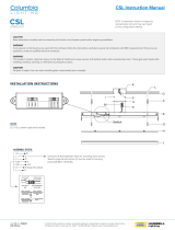
Zero Air Generator
1. Introduction
The Zero Air Generator (pn 31022) provides a convenient source of zero air
(air that contains no CO
2
or water vapor) for zeroing a gas analyzer where
normally a compressed-gas cylinder of zero air would be used. The Zero Air
Generator effectively eliminates the need for a cylinder of compressed gas and
the required pressure regulator and flow controller, making it extremely useful
in zeroing open- or closed-path infrared gas analyzers (IRGA) that are located
in remote field sites.
2. Cautionary Statements
• READ AND UNDERSTAND the Precautions section at the front of this
manual.
• WARNING
o Do not connect the Zero Air Generator to any source of
pressurized air, such as an external pump or a cylinder of
compressed gas.
• CAUTION
o Do not operate the Zero Air Generator pump with both
outlets, Out and Test, plugged.
3. Initial Inspection
Upon receipt of the Zero Air Generator, inspect the packaging and contents for
damage. File damage claims with the shipping company. Contact Campbell
Scientific to facilitate repair or replacement.
The Zero Air Generator ships with the instrument, three sets of 1/4-in
Swagelok
®
nuts and ferrules, and two 1.5V AA alkaline batteries.
4. Overview
The Zero Air Generator is a low-cost, handheld source of zero air (air that has
been scrubbed of CO
2
and water vapor) intended for zeroing infrared gas
analyzers (IRGAs). The Zero Air Generator (shown in FIGURE 4-1) can be
used to replace the traditional method of zeroing an IRGA requiring a cylinder
of compressed gas with a pressure regulator and flow controller. A simpler
source of zero air is particularly useful in remote field sites.
All IRGAs are subject to drift in the zero response due to aging over time,
changes in temperature, window contamination, etc. An IRGA should undergo
a zeroing procedure frequently to maintain peak accuracy. In many cases,
IRGAs are zeroed infrequently because of the cost and difficulty of providing a
source of zero air.

Zero Air Generator
2
FIGURE 4-1. Zero Air Generator
The Zero Air Generator makes it easy to zero an IRGA in the field. For open-
path IRGAs, such as the IRGASON or EC150 (sold by Campbell Scientific
®
,
Inc.) or the LI-7500 (sold by LI-COR
®
, Inc.), a zero/span shroud is also
required. For these open-path analyzers, the zero/span shroud is installed and
the Zero Air Generator is connected in either an open- or closed-loop
configuration. The small battery-powered pump in the Zero Air Generator
circulates a low flow through a bottle filled with molecular sieve that removes
CO
2
and water vapor, and pushes it through the zero/span shroud.
The Zero Air Generator may also be used to zero a closed-path IRGA such as
the EC155 (sold by Campbell Scientific
®
, Inc.), or the LI-6262, LI-7000, LI-
7200, or LI-840A (sold by LI-COR
®
, Inc.). Closed-path analyzers do not
require a zero/span shroud.
The Zero Air Generator includes a third connection that allows the user to
assess the status of the molecular sieve. This gives an indication of when to
replace the molecular sieve, ensuring that CO
2
and water vapor are always
completely removed.

Zero Air Generator
3
4.1 Accessories
4.1.1 Other Accessories
Plastic tubing
Bev-A-Line IV plastic tubing with an outer diameter of 1/4 in and inner
diameter of 1/8 in, is available as pn 7399. The tubing remains flexible even at
cold temperatures and holds up well in applications that require repeated
handling and flexing. Campbell Scientific recommends this tubing for the
plumbing connection between the Zero Air Generator and the instrument under
test.
4.1.2 Replacement Parts
AA alkaline cells
The power that operates the small pump of the Zero Air Generator is supplied
by a pair of AA alkaline cells. Campbell Scientific offers pn 26064 which is a
long-life 1.5 V, AA alkaline battery.
Molecular sieve
The Zero Air Generator scrubs an air sample of CO
2
and water vapor with a
13X molecular sieve. The sieve requires periodic replacement. Campbell
Scientific offers pn 27450, which is a bottle containing 250 g of 13X molecular
sieve beads ranging from 1.6 to 2.5 mm diameter.
Two 250 g bottles are required to replace the sieve.
Filter
The original filter of the Zero Air Generator can be replaced by the filter
available as pn 29998. The filter is an in-line, 2.5 cm (1.0 in) diameter, PTFE
membrane filter of 3-micron pore size with Luer lock connections.
Swagelok
®
plug
Spare 1/4-in Swagelok
®
plugs are available as pn 15891. This part is used to
plug a fitting when the accompanying tube is disconnected. Plugging the
fittings is necessary to keep the fittings clean and to avoid consumption of the
molecular sieve during storage. It is strongly recommended to replace plugs in
the event that those provided with the Zero Air Generator are lost or become
damaged.
NOTE

Zero Air Generator
4
Velcro
®
strap
A Velcro
®
strap is used as a lanyard to secure the Zero Air Generator to a
crossarm or other support when it is used in the field. If this strap is lost or
damaged it can be replaced with pn 4180, which is a 30 cm (12 in) length of
2.5 cm (1.0 in) wide Velcro
®
with a plastic loop. Longer or shorter straps are
also available. Contact Campbell Scientific for details.
5. Specifications
Dimensions
Length: 14.0 cm (5.5 in)
Width: 9.6 cm (3.8 in)
Height: 27.4 cm (10.8 in)
Weight: 1.16 kg (2.55 lb)
Operating temperature range: −20 to 50 °C
Capacity: 750 ml (holds approximately 450 g
molecular sieve)
Flow rate: 0.2 LPM (typical)
Power: two AA batteries
6. Operation
6.1 Theory of Operation
In normal operation, ambient air enters the Zero Air Generator through an In
port on the front of the module, flows through an inline filter, and is pushed by
a small pump into the top of a bottle containing molecular sieve. The
molecular sieve removes the CO
2
and water vapor from the air as it flows down
the length of the bottle. Scrubbed air enters a tube at the bottom of the bottle
and then emerges from the Out port at the front of the module.
The Test port provides scrubbed air pulled from the middle of the molecular
sieve, whereas the Out port has zeroed air removed from the bottom of the
molecular sieve. See FIGURE 6-1 for the configuration of the ports.

Zero Air Generator
5
FIGURE 6-1. Zero Air Generator port configuration
The Test connection pulls air from two inches above the bottom of the bottle of
molecular sieve. This air sample is used to monitor the effectiveness of the
molecular sieve scrubbing the air. Because unscrubbed air enters at the top and
flows downward, the molecular sieve will be consumed from the top down.
Measuring the CO
2
and water vapor from this Test port and comparing the
values to the readings from the bottom of the bottle shows when the molecular
sieve at the top of the bottle has been consumed. If air from the Test port
contains more CO
2
or water vapor than the air exiting the Out port, the
molecular sieve should be replaced. Molecular sieve 13X with 1.6 – 2.5 mm
bead diameter is recommended. Approximately 450 g is needed to refill the
bottle (see Section 4.1.2, Replacement Parts
(p. 3)).
The In port should either be connected to the exhaust side of an IRGA
zero/span shroud or sample cell, left capped (a tee-connection allows entry of
ambient air from under the Zero Air Generator cover, see FIGURE 6-2), or left
uncapped. If the Zero Air Generator is used in recirculating mode, the open
port of the tee will keep the IRGA near ambient pressure. The Out port or
Test port should be connected to the intake side of the IRGA zero/span shroud

Zero Air Generator
6
or sample cell. All connections should be made via tubing with1/4-in
Swagelok
®
connectors.
Do not operate the Zero Air Generator with both outlets, Out and
Test, plugged.
FIGURE 6-2. Internal connections of Zero Air Generator
6.2 Zeroing an Open-Path IRGA
The Zero Air Generator makes it easy to zero an IRGA in the field. For open-
path IRGAs, such as the IRGASON or EC150 (sold by Campbell Scientific
®
,
Inc.) or the LI-7500 (sold by LI-COR
®
, Inc.), a zero/span shroud is required.
Install the zero/span shroud according to the manufacturer’s instructions.
Secure the Zero Air Generator to the crossarm or other structure using the
Velcro
®
strap. Connect the Zero Air Generator to the IRGA zero/span shroud
in either an open-loop or a closed-loop configuration. FIGURE 6-3 shows the
zero/span shroud connected to an LI-7500 in an open-loop configuration.
FIGURE 6-4 shows the Zero Air Generator connected to an IRGASON in a
closed-loop configuration. Either configuration will give good results.
The closed-loop configuration will exhaust the molecular sieve more slowly,
which may be important if the Zero Air Generator is used extensively. The
instrument will operate for many hours in an open-loop configuration.
Normally, the batteries will have to be replaced a few times before the
molecular sieve must be replaced, even in open-loop operation.
Follow the manufacturer’s instructions to zero the specific IRGA. To ensure
the molecular sieve is removing all of the CO
2
and water vapor, compare the
IRGA readings by using the Test outlet.
NOTE

Zero Air Generator
7
FIGURE 6-3. Zero Air Generator connected to LI-7500 in open-loop
configuration
FIGURE 6-4. Zero Air Generator connected to IRGASON in closed-
loop configuration
6.3 Zeroing a Closed-Path IRGA
The Zero Air Generator may also be used with a closed-path IRGA in either an
open-loop or a closed-loop configuration. FIGURE 6-5 shows the Zero Air
Generator connected to an LI-840A (sold by LI-COR
®
, Inc.) in a closed loop
configuration. Connect the Out port to the LI-840A IN port and the LI-840A
OUT port to the Zero Air Generator In port. Turn the pump on to start the
flow of zero air. Follow the recommendations of the IRGA manufacturer for
the zero procedure.

Zero Air Generator
8
FIGURE 6-5. Zero Air Generator connected to LI-840A
7. Maintenance
7.1 Replacing Batteries
The Zero Air Generator ships with two AA alkaline cells. Refer to the
following instructions and figures to replace the batteries.
1. Make sure the switch is in the “OFF” position as shown on the lid of the
Zero Air Generator.
2. Loosen the three screws that attach the lid and remove the lid as shown.

Zero Air Generator
9
3. Slide the battery holder off its lid. The lid is held captive by a strip of
Velcro
®
. The battery holder is captive to the pump by wires.
4. Insert two AA cells into the battery holder, taking care to put them in the
proper orientation as indicated.
5. Replace the battery holder and lid in the reverse order.
Batteries will typically last approximately 45 hours of operation. The pumping
speed will depend on the charge state of the batteries, as shown in FIGURE
7-1. Replace the batteries if the pump seems to be running slower than normal,
or if it does not run at all. Replacement batteries can be obtained from
Campbell Scientific as pn 26064, but can usually be sourced locally. Any type
of AA cells may be used: rechargeable or disposable.

Zero Air Generator
10
FIGURE 7-1. Pumping speed relative to hours of use, indicating time
for battery replacement
7.2 Replacing Molecular Sieve
The molecular sieve in the Zero Air Generator requires periodic replacement.
Time for replacement can be determined by comparing the values of an air
sample taken from the Test port to those of an air sample taken at the Out port
as described in Section 6.1, Theory of Operation
(p. 4). Two bottles of pn 27450
are needed to fill the bottle when replacing the molecular sieve material as
described in the following steps and illustrations.
1. Loosen the three screws that attach the box lid as shown in step 1 of
Section 7.1, Replacing Batteries
(p. 8), and remove the lid.
2. Unscrew the two 1/8-in Swagelok
®
nuts.

Zero Air Generator
11
3. Loosen the four screws that clamp the bottle cap to the bracket
approximately one turn.
4. Slide tubes out until filters touch the bottle cap.
Pull gently at first increasing force just until the tubes begin
sliding out. Stop pulling when you feel the filter touch the bottle
cap. Pulling too hard will pull the filter off the end of the tube.
NOTE

Zero Air Generator
12
5. Remove the bottle, keeping it upright to avoid spilling the contents, and set
the O-ring aside for reassembly.
6. Empty the old molecular sieve into a disposal container and dispose
according to local regulations.
7. Fill the bottle with new molecular sieve until the sieve is mounded as
much as possible. Jiggle the bottle slightly to settle the beads and make
room for the tubes and filter.
8. Place O-ring on top of the bottle and secure the cap tightly to the bottle.
/