Interlogix 5402 & 5422 Metal Enclosure Assault Sensors Installation guide

Type
Installation guide

Interlogix 5402 & 5422 Metal Enclosure Assault Sensors use advanced technology to detect shock waves on sheet metal caused by cutting, sawing, or drilling attempts. Perfect for securing control panels, alarm housings, electrical panels, and junction boxes, these sensors feature an easy installation process. With no sensitivity adjustments needed, simply mount the sensor inside the enclosure and connect the wires. The sensor will automatically reset after an alarm, ensuring continuous protection. Remember to test the sensor annually to ensure proper operation.

Interlogix 5402 & 5422 Metal Enclosure Assault Sensors use advanced technology to detect shock waves on sheet metal caused by cutting, sawing, or drilling attempts. Perfect for securing control panels, alarm housings, electrical panels, and junction boxes, these sensors feature an easy installation process. With no sensitivity adjustments needed, simply mount the sensor inside the enclosure and connect the wires. The sensor will automatically reset after an alarm, ensuring continuous protection. Remember to test the sensor annually to ensure proper operation.

The 5402 and 5422 shock sensors respond to the shock waves
of sheet metal that is being cut, sawed, impacted, or drilled. This
quality makes it ideal for protecting sheet metal enclosures such
as control panels, alarm housings, electrical panels, and telephone
junction boxes. No sensitivity adjustments make installation quick
and easy.
The 5402 is a lithium battery powered, two-wire sensor. The 5422
is a 4-wire externally powered sensor operating from a
9-24 VDC supply. Both have closed loop outputs.
Sensor Operation
When the sensor is operational and detects an attack, the sensor
alarms, producing three responses:
1. The red LED on the sensor goes on for the period of time the
alarm loop is open (2-6 seconds).
2. The loop impedance of the sensor changes from <15 ohms
(closed) to >1.0 megaohms (open).
3. This is registered by the alarm panel as an alarm. After an
alarm, the sensor automatically resets itself, while the LED
extinguishes simultaneously.
DESCRIPTION
Sheet metal enclosures to be protected shall not exceed 2 x 4 x 1 ft.
(61 x 122 x 30.5 cm), and shall have a maximum wall thickness of
0.135 inches (0.343 cm). The enclosure must be solid sheet
metal, have all sides connected (welded, bolted, etc.), and the lid
attached by hinges or screws.
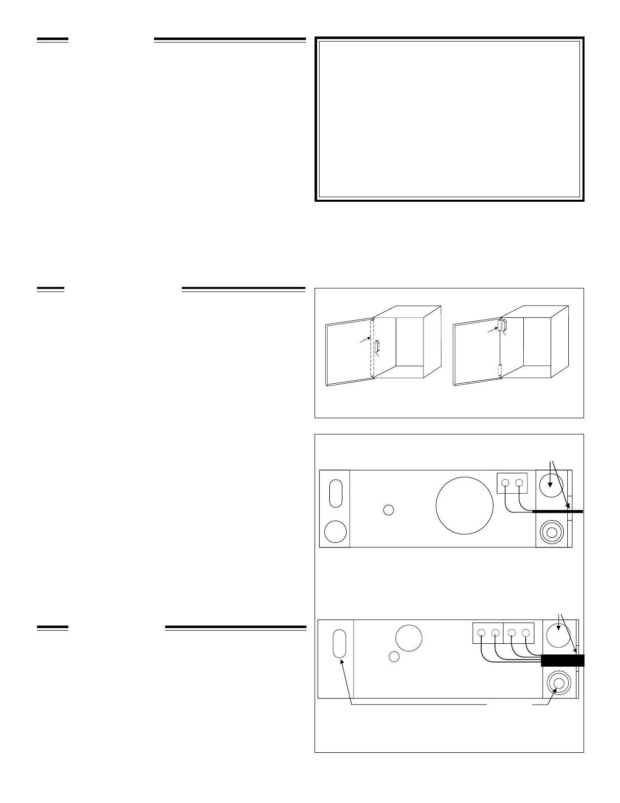
Locate the sensor inside the enclosure on the side wall on or
near the hinge. If the hinge runs the length of the side, center the
sensor vertically. If the enclosure has multiple hinges, place the
sensor next to the hinge nearest the middle of the enclosure (see
Figure 1).
Mounting the Sensor
1. Clean the area where the sensor will be mounted with a 50/50
solution of isopropyl alcohol and water on a clean cloth.
2. Dry the area.
3. Peel the backing from one side of the tape pad. Center the
tape pad on the back of the sensor. The tape pad must be
flat against the plastic case.
4. Remove the remaining backing paper from the tape pad.
Place the sensor against the metal and press firmly.
NOTE: Although the 5402 and 5422 have inherent false alarm
immunity, a few simple precautions must be observed to prevent
false detections.
1. Mount the enclosure and lid securely so that they do not
rattle. Use foam pads to eliminate lid rattle.
2. The enclosure should be clear of vibrating objects (i.e.,
bells, machinery, motors, etc.).
STEP 1 - MOUNTING
Remove the cover by depressing the snap in the slot at the end of
the sensor and lifting the cover. Connect wires to the terminal
block as labeled on the circuit board (see Figure 2).
Run the wires out the terminal block end of the plastic base. Notch
out center wire exit in the cover and snap in place.
STEP 2 - WIRING
Figure 1. Solid Hinge
Multiple Hinges
5422 Wiring Guide
5402 Wiring Guide
Figure 2.
Sentrol Models
5402 and 5422
Metal Enclosure Assault Sensors
UL and ULC Listed
Installation Instructions
LED
Power
Input
Alarm
Loop
Wire Exits
Screw Holes
Out
Out
Ð
+
Sensor
Hinge
Sensor
Hinge
Alarm
Loop
LED
Battery
Out
Out
Wire Exits
STEP 3 - TESTING
NOTE: Be sure to test the sensor at least annually to ensure
proper operation.
To verify sensor operation, lightly scrape the metal shaft of a
screwdriver (8" or larger) back and forth against the metal edge of
the enclosure (see Figure 3). The LED should light. Do not use the
side with sensor to test as it will be most sensitive. If the sensor
range is not sufficient, add another sensor (see Figure 4).
Figure 3. Vibration test
Figure 4. Two sensor placement
Sensor
Screwdriver
Sensor
Sensor
DIMENSIONS
R
3.46"
8.8 cm
0.84"
2.1 cm
1.10"
2.8 cm
SPECIFICATIONS
ALL MODELS
Resistance: Normal ............................................................................................................................... <15 ohms (closed)
Alarm.......................................................................................................................... >1.0 megaohms (open)
Time Open on Alarm ........................................................................................................................................... 2-6 seconds
Operational Voltage (5422) ...................................................................................................................................... 9-24 VDC
Current Draw (5422) .....................................................................................................................................15 mA maximum
Number of Leads...................................................................................................................................... 2 (5402) or 4 (5422)
Maximium Loop Rating...................................................................................................................................24 VDC, 50 mA
Wire Lead Size.................................................................................................................................................... 16-22 gauge
Mounting ..................................................................................................................................................................Tape pad
Dimensions ................................................................................................................................... 3.46" L x 1.1" W x 0.84" H
(8.8 cm x 2.8 cm x 2.1 cm)
ORDERING INFORMATION
G-3763-0499
1030900 Rev A
Model Description Loop Color Listing
Number Configuration
5402-W Lithium battery, 2-wire Closed loop, NC Grey UL/ULC
5422-W External power, 4-wire Closed loop, NC Grey UL/ULC
  • Page 1 1
  • Page 2 2

Interlogix 5402 & 5422 Metal Enclosure Assault Sensors Installation guide

Type
Installation guide

Interlogix 5402 & 5422 Metal Enclosure Assault Sensors use advanced technology to detect shock waves on sheet metal caused by cutting, sawing, or drilling attempts. Perfect for securing control panels, alarm housings, electrical panels, and junction boxes, these sensors feature an easy installation process. With no sensitivity adjustments needed, simply mount the sensor inside the enclosure and connect the wires. The sensor will automatically reset after an alarm, ensuring continuous protection. Remember to test the sensor annually to ensure proper operation.

Ask a question and I''ll find the answer in the document

Finding information in a document is now easier with AI