
AlphaCell HP
Users Guide
AlphaCell HP Battery
Effective: July 2011

Power
Alpha Technologies
®

3
745-680-C5-002, Rev. A
AlphaCell
TM
HP Battery Users Guide
Storage, Maintenance and Deployment
745-680-C5-001, Rev. A
Effective Date: July, 2011
Copyright
©
2011
Alpha Technologies, Inc.
Photographs contained in this manual are for illustrative purposes only. These photographs may not match your
installation.
Operator is cautioned to review the drawings and illustrations contained in this manual before proceeding. If there
are questions regarding the safe operation of this powering system, please contact Alpha Technologies or your
nearest Alpha representative.
Alpha shall not be held liable for any damage or injury involving its enclosures, power supplies, generators,
batteries or other hardware if used or operated in any manner or subject to any condition not consistent with its
intended purpose or is installed or operated in an unapproved manner or improperly maintained.
Contacting Alpha Technologies: www.alpha.com
or
For general USA sales information and customer service (7 AM to 5 PM, Pacic Time), call
1 800 863 3930
For complete technical support in the USA, call
7 AM to 5 PM, Pacic Time or 24/7 emergency support
1 800 863 3364
For Sales information and Technical Support in Canada, call
1 800 667 8743
NOTE:
NOTE:
NOTE:

745-680-C5-002, Rev. A
4
Table of Contents
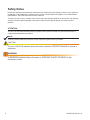
Safety Notes ....................................................................................................................................................... 6
Battery Maintenance Guidelines......................................................................................................................... 7
Recycling and Disposal Instructions ................................................................................................................... 7
Important Storage Practices ............................................................................................................................... 8
Electrical Safety .................................................................................................................................................. 8
Chemical and Mechanical Safety ....................................................................................................................... 9
1.0 Introduction .......................................................................................................................................... 10
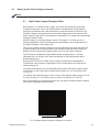
1.1 Description ............................................................................................................................... 11
1.2 Operating Conditions .............................................................................................................. 12
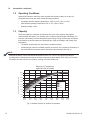
1.3 Capacity .................................................................................................................................. 12
1.3.1 Ratings ......................................................................................................................... 13
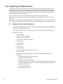
2.0 Preparing for Maintenance .................................................................................................................. 14
2.1 Required Tools and Equipment .............................................................................................. 14
3.0 Periodic Maintenance Tasks and Schedule ......................................................................................... 15
3.1 Monthly Remote Status Monitoring ........................................................................................ 15
3.2 Quarterly Preventive Maintenance ......................................................................................... 16
3.3 AlphaCell
TM
Battery Maintenance Log .................................................................................... 18
3.4 Battery Evaluation Procedures ............................................................................................... 20
3.5 Battery Refurbishment Plan .................................................................................................... 21
4.0 Battery System Float Charging ............................................................................................................ 22
4.1 Alpha Power Supply Charging Prole .................................................................................... 23
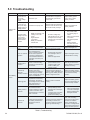
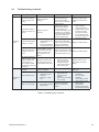
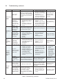
5.0 Troubleshooting ................................................................................................................................... 24
6.0 Battery Parameters by Model Number ................................................................................................ 27
7.0 Warranty and Return Information ........................................................................................................ 28
7.1 AlphaCell
TM
Limited Warranty.................................................................................................. 28
7.2 Battery Maintenance Report for Return Authorizations .......................................................... 30

5
745-680-C5-002, Rev. A
Figures and Tables
Fig. 1, Capacity vs Storage Time ........................................................................................................... 8
Fig. 2, Series Connected String of Batteries ........................................................................................11
Fig. 3, Parallel String of Batteries .........................................................................................................11
Fig. 4, Available Capacity vs. Ambient Temperature ........................................................................... 12
Fig. 5, Flow Chart, Monthly Status Monitoring ..................................................................................... 15
Fig. 6, Flow Chart, Quarterly Preventive Maintenance ........................................................................ 16
Fig. 7 Flow Chart for Battery Refurbishment Plan ............................................................................... 21
Fig. 8, Charger Modes ......................................................................................................................... 23
Table 1, Conductance values, new vs. suspect batteries .................................................................... 20
Table 2, Troubleshooting ..................................................................................................................... 24
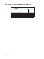
Table 3, Battery Parameters, Current Models ..................................................................................... 27
Table 4, Warranty Periods for AlphaCell
TM
batteries ............................................................................ 28

745-680-C5-002, Rev. A
6
Safety Notes
Review the drawings and illustrations contained in this manual before proceeding. If there are any questions
regarding the safe installation or operation of the system, contact Alpha Technologies or the nearest Alpha
representative. Save this document for future reference.
To reduce the risk of injury or death, and to ensure the continued safe operation of this product, the following
symbols have been placed throughout this manual. Where these symbols appear, use extra care and
attention.
The use of ATTENTION indicates specic regulatory/code requirements that may affect the placement of
equipment and installation procedures.
A NOTE provides additional information to help complete a specic task or procedure.
The use of CAUTION indicates safety information intended to PREVENT DAMAGE to material or
equipment.
A WARNING presents safety information to PREVENT INJURY OR DEATH to the
technician or user.
CAUTION!
NOTE:
ATTENTION:
WARNING!

7
745-680-C5-002, Rev. A
Lead-acid batteries contain dangerous voltages, currents, and corrosive material. Battery
installation, maintenance, service, and replacement must only be performed by authorized
personnel.
Battery Maintenance Guidelines
• For optimal performance, inspect batteries every 6 months for:
Signs of battery cracking, leaking or swelling. The battery should be replaced immediately by
authorized personnel using a battery of the identical type and rating (match conductance, voltages,
and date codes as specied in this document).
Signs of battery cable damage. Battery cable should be replaced immediately by authorized
personnel using replacement parts specied by vendor.
Loose battery connection hardware. Refer to documentation for the correct torque and connection
hardware for the application.
• Do not attempt to remove the vents (valves) from the AlphaCell HP battery or add water. This is a safety
hazard and voids the warranty.
• Apply NO-OX grease on all exposed connections.
• When necessary, clean up any spilled electrolyte in accordance with all federal, state, and local
regulations or codes.
• Follow approved storage instructions.
• Always replace batteries with those of an identical type and rating. Never install untested batteries.
• Do not charge batteries in a sealed container. Each individual battery should have at least 1/2 inch of
space between it and all surrounding surfaces to allow for convection cooling.
• All battery compartments must have adequate ventilation to prevent an accumulation of potentially
dangerous gas. Never place batteries in a sealed enclosure. Extreme caution should be used when
maintaining and collecting data on the battery system.
Recycling and Disposal Instructions
• Spent or damaged batteries are considered environmentally unsafe as they contain lead and dilute
sulfuric acid. They should not be "thrown away" with common refuse.
• Always recycle used batteries in accordance with federal, state, provincial, and local regulations. The
Alpha Group provides recycling services. Call 800 863 3930 or contact your local Alpha representative.
WARNING!

745-680-C5-002, Rev. A
8
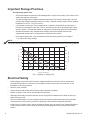
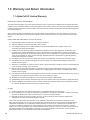
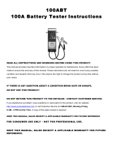
Fig. 1, Capacity vs. Storage Time
During storage please note:
• All lead acid batteries experience self-discharge while in open circuit storage. This causes circuit
voltage and capacity to decrease.
• The self-discharge rate is related to ambient temperature. The lower the temperature, the less
the discharge. Batteries should be stored in a clean, ventilated, and dry location with an ambient
temperature of 32ºF to 77ºF (0ºC to 25ºC).
• It is important to track open circuit voltage which is related to the density of the electrolyte. If
the open circuit voltage is lower than 12.6V or the batteries have been stored beyond the limits
shown in Figure 1, the batteries should be charged to avoid damage caused by self-discharge.
• All batteries should be fully charged before storage. Record the storage date and next
supplemental charge date in a maintenance record and on the battery.
• Upon battery deployment, verify all batteries within each string measure in the range of
+/- 0.3Vdc of the string average.
Electrical Safety
• Lethal voltages are present within the power supply and electrical enclosures. Never assume that
an electrical connection or conductor is not energized. Check circuits with a volt meter prior to any
installation or removal procedure.
• Observe circuit polarities.
• Always use the buddy system when working under hazardous conditions.
• Ensure no liquids or wet clothes contact internal components.
• Hazardous electrically live parts inside this unit are energized from batteries even when the AC input
power is disconnected.
• Use an insulated blanket to cover exposed portions of the battery system when performing extended
maintenance that could result in personal or equipment contact with the energized conductors.
• Certain types of rectier circuits used in charging the battery may not include a line isolating transformer.
In these cases extreme caution should be used when maintaining and collecting data on the battery
system.
The product warranty is void if the batteries are not stored and recharged in accordance with these guidelines.
NOTE:
Important Storage Practices
0
3
6
9 12
15
18 21
24
2.1
2.13
2.16
2.15
2.17
2.14
2.12
2.11
80%
95%
90%
100%
85%
75%
70%
Percent State of Charge
OCV Per Cell
Storage Time (Months)
77°F/
25°C
68°F/
20°C
86°F/
30°C
104°F/
40°C

9
745-680-C5-002, Rev. A
Chemical Hazards
Any liquid emissions from a valve-regulated lead-acid (VRLA) battery contains dilute sulfuric acid, which is
harmful to the skin and eyes. Emissions are electrolytic and are electrically conductive and corrosive.
To avoid injury:
• Servicing and connection of batteries shall be performed by, or under the direct supervision of, personnel
knowledgeable of batteries and the required safety precautions.
• Always wear eye protection, rubber gloves, and a protective vest when working near batteries. To avoid
battery contact, remove all metallic objects, (such as rings or watches), from your person.
• Batteries produce explosive gases. Keep all open ames and sparks away from batteries.
• Use tools with insulated handles, do not rest any tools on top of batteries.
• Batteries contain or emit chemicals known to the State of California to cause cancer and birth defects
or other reproductive harm. Battery post terminals and related accessories contain lead and lead
compounds. Wash hands after handling (California Proposition 65).
• If any battery emission contacts the skin, wash immediately and thoroughly with water. Follow your
company’s approved chemical exposure procedures.
• Neutralize any spilled battery emission with the special solution contained in an approved spill kit or with
a solution of one pound (454g) bicarbonate of soda to one gallon (3.8l) of water. Report a chemical spill
using your company’s spill reporting structure and seek medical attention if necessary.
• Always replace batteries with those of an identical type and rating (match conductance, voltages, and
date codes as specied in this document).
• Never install old or untested batteries.
• Prior to handling the batteries, touch a grounded metal object to dissipate any static charge that may have
developed on your body.
• Use special caution when connecting or adjusting battery cabling. An improperly or unconnected battery
cable can make contact with an unintended surface that can result in arcing, re, or a possible explosion.
• A battery showing signs of cracking, leaking, or swelling should be replaced immediately by authorized
personnel using a battery of identical type and rating.
Mechanical Safety
• Keep hands and tools clear of fans.
• Fans are thermostatically controlled and will turn on automatically.
• Power supplies can reach extreme temperatures under load.
• Use caution around sheet metal components, especially sharp edges.
• Depending on the model, batteries can weigh anywhere from 25 to 100 pounds (11kg to 45kg). Exercise
care when handling and moving batteries. Use proper handling equipment.
WARNING!

745-680-C5-002, Rev. A
10
The purpose of this guide is to provide the user with the necessary information to maintain batteries in storage
and deploy batteries in Alpha Powering systems, as well as perform battery testing, install replacements and
recycling.
This manual guides you through periodic maintenance checks and troubleshooting of the AlphaCell HP Thin
Plate Pure Lead AGM battery.
Adherence to the procedures and practices detailed in this guide will not only insure the battery operates per
specications, but also provides the proper backup for the Alpha Powering system in which it is installed.
To achieve these goals, this guide will address the following topics:
• The storage and maintenance of new battery inventory.
• Deployment of AlphaCell HP batteries into Alpha Power systems.
• Proper preventiative maintenance practices for AlphaCell HP batteries.
• Replacement and recycling of AlphaCell HP batteries.
• Warehousing, testing, and redeployment of reuseable AlphaCell HP batteries.
• How to keep proper maintenance records for troubleshooting and/or Warranty claims.
1.0 Introduction

11
745-680-C5-002, Rev. A
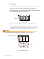
1.1 Description
The AlphaCell HP battery is a lead acid battery that facilitates an oxygen recombination cycle.
You can connect multiple strings of batteries in parallel. This provides a system whose
capacity equals the sum capacity of all the strings. For example, in Fig. 3, two 36V 90Ah
capacity strings are connected in parallel to provide a nominal 36V at 180Ah.
A 12V battery is made up of six 2V cells internally connected to provide 12 volts.
The battery system is a group of 12V batteries connected in a series string to provide a
higher voltage system. In Fig. 2, three of the nominal 12V batteries are connected in series to
provide an 18 cell system with a nominal voltage of 36V.
Fig. 3, Parallel String of Batteries
Fig. 2, Series String of Batteries
(For illustration purposes, a 36Volt string is shown. 48Volt strings are also available)
Alpha highly recommends fusing in single and parallel string congurations.
to power supply: red (+), black (-)
inline fuse
inline
fuse
to
power supply: red (+), black (-)
1B
3A
2B3B
1A2A
upper tray
lower
tray
3A 1A2A
inline fuse
[Front]
WARNING!

745-680-C5-002, Rev. A
12
1.2 Operating Conditions
AlphaCell HP batteries, which are valve regulated and virtually sealed, do not give off
perceptible amounts of gas under normal operating conditions.
• Acceptable ambient operating temperature: -40ºF to 131ºF (-40ºC to 55ºC)
• Ideal ambient operating temperature: 68ºF to 77ºF (20ºC to 25ºC)
• Ambient humidity: ≤ 95%
1.3 Capacity
The actual capacity is related to the utilization ratio of the active positive and negative
materials within the battery. The utilization ratio is inuenced by the depth of discharge, the
structure of the battery, and the manufacturing technology. During normal usage, the factors
that inuence the actual capacity are discharge rate, depth of discharge, end voltage, and
temperature.
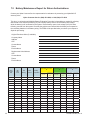
• The higher the discharge rate, the lower the available capacity.
• As batteries get colder, the available capacity is reduced. This is related to the kinetics of
the electrochemical reactions and the resistivity of the electrolyte (See Fig. 4).
NOTE:
Although the battery can be operated at temperatures below -4ºF (-20ºC), the capacity and ability to
discharge will be dramatically decreased. Similarly, temperatures approaching 122ºF (50ºC) will increase
electrolyte loss and corrosion of the plates, resulting in a shorter battery life.
1.0 Introduction, continued
Fig. 4, Available Capacity vs. Ambient Temperature
-40°F/
-40°C
-22°F/
-30°C
-4°F/
-20°C
14°F/
-10°C
32F/
0°C
50°F/
10°C
68°F/
20°C
86°F/
30°C
104°F/
40°C
20%
30%
50%
70%
90%
10%
80%
60%
100%
40%
0%
Percent Rated Capacity Available
Eciency VS. Temperature
AlphaCell 3.5HP and 4.0HP
4.0HP
3.5HP
Typical Gel

13
745-680-C5-002, Rev. A
Amps
End Voltage 15min 30min 45min 1hr 2hr 3hr 4hr 5hr 8hr 10hr 20hr
1.85 162.6 106.4 80.5 65.3 38 27.1 21.2 17.4 11.4 9.3 4.9
1.80 174.7 112.1 84.2 67.9 39.2 27.9 21.8 17.9 11.8 9.6 5.1
1.75 185.6 117.2 87.3 70.2 40.3 28.6 22.3 18.4 12.1 9.9 5.2
1.70 194.9 121.3 89.9 72 41.1 29.2 22.7 18.7 12.3 10 5.3
Power (Watts)
End Voltage 15min 30min 45min 1hr 2hr 3hr 4hr 5hr 8hr 10hr 20hr
1.85 312.2 206 156.9 127.9 75.4 54.2 42.5 35.1 23.1 18.9 9.9
1.80 331 215.4 163.1 132.4 77.5 55.5 43.5 35.9 23.7 19.4 10.2
1.75 347.6 223.6 168.3 136.2 79.2 56.7 44.4 36.6 24.2 19.8 10.5
1.70 361.7 230.3 172.6 139.2 80.6 57.5 45 37.1 24.5 20.1 10.7
A/H Capacity
End Voltage 15min 30min 45min 1hr 2hr 3hr 4hr 5hr 8hr 10hr 20hr
1.85 40.7 53.2 60.4 65.3 75.9 81.3 84.7 87.1 91.5 93.4 98.6
1.80 43.7 56.1 63.1 67.9 78.5 83.8 87.2 89.7 94.3 96.2 101.7
1.75 46.4 58.6 65.5 70.2 80.6 85.9 89.3 91.8 96.5 98.6 104.4
1.70 48.7 60.7 67.4 72 82.2 87.5 91 93.5 98.3 100.4 106.6
1.0 Introduction, continued
1.3 Capacity, continued
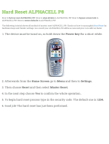
1.3.1 Ratings
3.5 HP Ratings
Amps
End Voltage 15min 30min 45min 1hr 2hr 3hr 4hr 5hr 8hr 10hr 20hr
1.85 198.7 128.3 95.9 77 43.7 30.8 24 19.4 12.5 10.1 5.4
1.80 212.8 134.6 99.7 79.7 44.9 31.6 24.5 19.8 12.8 10.4 5.6
1.75 225.2 139.9 102.9 81.9 45.9 32.2 25 20.2 13.1 10.6 5.7
1.70 235.7 144.3 105.5 83.7 46.7 32.8 25.4 20.5 13.3 10.8 5.8
Power (Watts)
End Voltage 15min 30min 45min 1hr 2hr 3hr 4hr 5hr 8hr 10hr 20hr
1.85 383.9 251.6 189.4 152.7 87.5 61.9 48.2 39 25.3 20.5 11
1.80 406.8 261.8 195.7 157.2 89.6 63.3 49.3 39.9 25.9 21 11.3
1.75 426.7 270.5 200.9 160.9 91.3 64.5 50.1 40.6 26.4 21.3 11.5
1.70 443.1 277.4 205.1 163.8 92.6 65.4 50.8 41.2 26.7 21.6 11.6
A/H Capacity
End Voltage 15min 30min 45min 1hr 2hr 3hr 4hr 5hr 8hr 10hr 20hr
1.85 49.7 64.2 72 77 87.5 92.5 95.8 96.9 100.3 101.3 108.8
1.80 53.2 67.3 74.8 79.7 89.8 94.8 98.1 99.2 102.7 103.8 111.7
1.75 56.3 70 77.2 81.9 91.8 96.7 100 101.1 104.7 105.9 114
1.70 58.9 72.1 79.1 83.7 93.3 98.2 101.5 102.6 106.3 107.5 115.8
4.0 HP Ratings

745-680-C5-002, Rev. A
14
2.0 Preparing for Maintenance
The battery system should be remotely monitored monthly and physically inspected quarterly. If the
battery system has an automatic monitoring system to gather the electrical and environmental data,
the monthly checks should consist of evaluating the recorded data and visiting any site that does not
meet the specications listed in the detailed procedures below. At a minimum each site needs to be
physically inspected every three months.
You do not have to measure the electrolyte specic gravity or add water to the cells.
All batteries in the string should be numbered to facilitate recording and analysis of data unique to
each unit.
Notify anyone affected by the intended maintenance or troubleshooting activity. This should include
but not be limited to anyone responsible for the status monitoring equipment at the head-end or NOC.
2.1 Required Tools and Equipment
Prior to beginning maintenance, ensure that all required tools and equipment, including safety
equipment, is available and functional.
The following is a list of the minimum equipment required to maintain and troubleshoot the
AlphaCell HP battery:
• Digital voltmeter
• Socket wrenches, insulated
• Box end wrenches, insulated
• Torque wrench calibrated in inch/lbs
• Rubber gloves
• Full face shield
• Safety Glasses
• Plastic apron
• Portable eyewash
• Spill kit, including sodium bicarbonate solution
• Fire extinguisher
• Optional equipment, depending on the type of maintenance being performed,
includes:
• True RMS Volt Meter with DC Amp Clamp
• Midtronics Conductance Meter
• 100 amp momentary load test set
• System load bank (DC if to be performed at the battery and AC if to be performed
by loading a power supply output— contact your Alpha Sales Representative for
purchasing information).
• NO-OX Corrosion Inhibitor
• Paper Towels and/or rags

15
745-680-C5-002, Rev. A
3.0 Periodic Maintenance Tasks and Schedule
The following tasks are to be performed on a monthly and quarterly schedule.
The following maintenance procedure requires a fully functional status monitoring system capable of
remotely measuring and recording the following data on a periodic basis:
• Battery Temperature
• Individual Battery Voltage
• Total Battery String Voltage
Please note: If status monitoring is not available these checks need to be made during the quarterly
onsite visit and any batteries not meeting the minimum requirement must be addressed at such time.
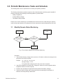
Procedure
1. If any individual battery voltage varies more than 0.5V above or below the average for the
string then a site visit is required.
Example V1 = 13V, V2 = 13V, V3=14V
Average voltage = 13.3V
If V3 greater than average by 0.5V, then a site visit is required
2. If the RTS temperature is greater than 10 degrees C above the current regional ambient
temperature then a site visit is required.
3. Prioritize site visits based on highest RTS temperatures and battery voltages
4. Visit the site within 30 days and remedy the problem by replacing the bad battery or
batteries and reset quarterly maintenance.
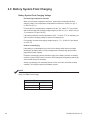
Fig. 5, Flow Chart for Monthly Remote Status Monitoring
3.1 Monthly Remote Status Monitoring
Review Status
Monitoring Data
Battery Voltage
>0.5V Above/Below
String Average
RTS
Temperature >10°C
above Ambient
Monitor as per PM
Program
Perform
Quarterly PM
No No
Yes
Yes

745-680-C5-002, Rev. A
16
3.2 Quarterly Preventive Maintenance
Required Equipment
• True RMS Volt Meter with DC Amp Clamp
• Midtronics Conductance Battery Tester
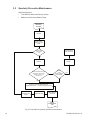
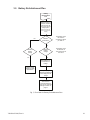
Fig. 6, Flow Chart for Quarterly Preventive Maintenance
Yes
No
Yes
Yes
No
Replace the individual failed battery with
a battery that is within +/- .3 Volts of the string average.
Battery String
Float Current
>0.5A
Log each battery’s
conductance and
voltage
Disconnect
Batteries
Record Information
on Site Visit Record
Monitor as per PM
Program
Site Visit
Battery
Refurbishment
Plan
Return battery to
warehouse
Remote Status
Monitoring
Procedure
Ensure Power
Supply is in Float
Mode
Battery
> 0.5V
from the average
string voltage
No
Does the individual battery pass
the Evaluation Procedure #1
outlined in Section 3.4?
(see page 18)
Replace the string

17
745-680-C5-002, Rev. A
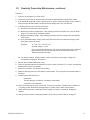
3.2 Quarterly Preventive Maintenance, continued
Procedure
1. Verify the power supply is in Float mode.
2. Use the DC Amp clamp to measure and record each individual battery string’s oat current.
3. If the individual string oat current is greater than 0.5 amps, replace the battery string. Measure
and record the individual battery conductance and voltage on the Site Visit Record.
4. If the string oat current is less than 0.5 amps,
4.1 Disconnect the batteries from the system
4.2 Measure the battery conductance. If any reading is below the suspect level, refer to Table 1,
page 20, for mhos values for battery models.
4.3 Measure the battery voltage. If any reading is less than 12.6V then replace all those batteries
in the string.
4.4 If any individual battery voltage varies more than 0.5V above or below the average for the
string then replace the string.
Example: V1 = 13V, V2 = 13V, V3=14V
Average voltage = 13.3V
If V3 is greater than average by 0.5V, then the batteries should be replaced.
Batteries removed from the site should then be tested per Section 3.5,
"Battery Refurbishment Plan".
4.5 Log the site location, battery location, model, manufacturer date codes, voltage and
conductance readings for all batteries.
5. Record data on Battery Maintenance log.
6. Verify the spacing between the batteries from front to back is at least 1/2" or 13mm, and adjacent
batteries do not touch one another.
7. Ensure the enclosure is clean and free of debris.
8. Measure and record the top center battery's temperature. This is typically the warmest battery in
the string.
9. Visually inspect the batteries for:
Cleanliness
Terminal damage or evidence of heating or overheating
Container or cover damage
10. Check terminal posts for signs of corrosion. If corrosion is present, neutralize with a solution of
1 lb (454g) sodium bicarbonate (baking soda) to 1 gallon (3.8l) of water. Rinse and dry.
11. Verify terminal posts are coated with NO-OX grease or a spray-on protectant. Reapply as
needed.
12. Retorque all the interunit connecting hardware to the values noted in Table 3 on page 27.

745-680-C5-002, Rev. A
18
3.3 AlphaCell
HP Battery Maintenance Log
Follow this sample when lling out the maintenance log (following page).
Evaluation Procedure
#1
Evaluation Procedure
#2
Evaluation Procedure
#3
Vdc
Float
No
Load
Conductance
mhos @
77°F
Vdc 24
Hour
OCV
Conductance
mhos @
77°F/25°C
Vdc @
100A after
10 seconds
Vdc 24
Hour
OCV
A 1 4.0 HP 4/11 3/11 .2 70° 13.4 2100
A 2 4.0 HP 4/11 3/11 .2 70° 13.5 2087
A 3 4.0 HP 4/11 3/11 .2 70° 13.4 2100
B 1 4.0 HP 4/11 3/11 .1 70° 13.4 2087
B 2 4.0 HP 4/11 3/11 .1 70° 13.4 2100
B 3 4.0 HP 4/11 3/11 .1 70° 13.6 2087
A 1 4.0 HP 4/11 3/11 7/8 .1 85° 13.3 2100
A 2 4.0 HP 3/11 7/8 .1 85° 13.3 2087
A 3 4.0 HP 3/11 7/8 .1 85° 13.4 2100
B 1 4.0 HP 3/11 7/8 .1 85° 13.2. 2087
B 2 4.0 HP 3/11 7/8 .1 85° 13.2 2100
B 3 4.0 HP 3/11 7/8 .1 85° 13.2 2087
String
Battery Type
Battery
Initial Install Date
Mfr. Date Code
PM Date
Float Current
Battery Temp
Node / Location
Power Supply Type
Load (kW)

19
745-680-C5-002, Rev. A
3.3 AlphaCell™
HP Battery Maintenance Log
Node / Location
Power Supply Type
Load (kW)
Evaluation Proce-
dure #1
Evaluation Procedure
#2
Evaluation Procedure
#3
Vdc
Float
No
Load
Conductance
mhos @
77°F
Vdc 24
Hour
OCV
Conductance
mhos @
77°F/25°C
Vdc @
100A after
10 seconds
Vdc
24
Hour
OCV
String
Battery Type
Battery
Initial Install Date
Mfr. Date Code
PM Date
Float Current
Battery Temp

745-680-C5-002, Rev. A
20
To help identify batteries approaching end of life in an operating power system, test #1 should be performed at each
maintenance interval. For batteries not installed in an operating power system, test #2 or #3 may be performed. For
accuracy, tests must be performed on fully charged batteries.
A battery failing any of the following combined tests is dened as a faulty battery. The battery will be replaced under the
terms of the warranty if within the dened warranty period.
Evaluation Procedure 1
Conductance/Impedance Test – Measure the conductance of each battery. Any battery that possesses a conductance
that is 50% less than the initial reading taken at the point of install can be considered suspect of being below 70%
capacity and should be evaluated further. The battery temperature must be approximately the same each time this reading
is taken (see Table 1 below). Use temperature compensation feature when using Midtronics meter.
AND
Float Voltage Test – Measure the oat voltage of each battery in the string that is on oat charge. Any battery in the string
measured at 13.2 volts or less is a suspect battery and should be further evaluated with the steps below. Any battery
below 12.6 volts should be replaced. The 13.2 & 12.6 voltage values are based on a 77˚F (25˚C) temperature. Adjust the
voltage for higher or lower temperatures by 0.0168 Volts per battery per degree Fahrenheit. The higher the temperature
above 77˚ F (25˚C) the lower the voltage will have to be adjusted and vice-versa for temperature below 77˚F (25˚C). (i.e.:
at a temp of 89˚F (32˚C) would have a corresponding oat voltage of 13.0 volts).
Evaluation Procedure 2
Conductance/Impedance Test – Measure the conductance of each battery. Any battery that possesses a conductance
that is 50% less than the initial reading taken at the point of install can be considered suspect of being below 70%
capacity and should be evaluated further. The battery temperature must be approximately the same each time this reading
is taken. Consult table 1 below for guidance. Use temperature compensation feature when using Midtronics meter.
AND
24 Hour Open Circuit Test – Measure the open circuit voltage of the suspected battery 24 hours after the battery has
come off of oat charge. Care must be taken to ensure that the battery is at full state of charge when it is disconnected
from the power supply. The battery should exhibit a voltage about 12.60V. A battery below this voltage should be replaced.
A fully charged battery below 12.6 volts is below 70% capacity, but a battery above 12.6 volts is not necessarily above
70% in capacity. Batteries that have been sitting for extended periods should be recharged after 6 months or when they
reach 12.48 volts (75% capacity), which ever comes rst depending on the storage temperature.
Evaluation Procedure 3
24 Hour Open Circuit Test – Measure the open circuit voltage of the suspected battery 24 hours after the battery has
come off of oat charge. Care must be taken to ensure that the battery is at full state of charge when it is disconnected
from the power supply. The battery should exhibit a voltage about 12.60 volts. A battery below this voltage should be
replaced. A fully charged battery below 12.6 volts is below 70% capacity, but a battery above 12.6 volts is not necessarily
above 80% in capacity. Batteries that have been sitting for extended periods should be recharged after 6 months or when
they reach 12.48 volts (75% capacity), which ever comes rst depending on the storage temperature.
AND
100A Load Test – Measure the voltage of each battery at the end of a 10 second 100-amp load test. Again, the
temperature must be equivalent to that of the original test performed at the point of installation. A signicant drop in
voltage versus the previous test will indicate deterioration of the battery. A 12-volt battery that falls below 10.80 volts
should be considered faulty and should be replaced.
To maintain consistent test results, ensure the same Midtronics conductance tester is used for each test cycle.
NOTE:
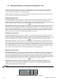
3.4 Battery Evaluation procedures for AlphaCell™ HP
Midtronics Conductance
Models 3200/micro CELLTRON
3.5 HP 4.0 HP
Approximate Conductance Values (mhos)
Healthy Battery @ 77°F (25°C)
1400-1850 1700-2500
Suspect Battery @ 77°F (25°C) in mhos <680 <840
Table 1, Conductance values, healthy vs. suspect batteries
Page is loading ...
Page is loading ...
Page is loading ...
Page is loading ...
Page is loading ...
Page is loading ...
Page is loading ...
Page is loading ...
Page is loading ...
Page is loading ...
Page is loading ...
Page is loading ...
-
 1
1
-
 2
2
-
 3
3
-
 4
4
-
 5
5
-
 6
6
-
 7
7
-
 8
8
-
 9
9
-
 10
10
-
 11
11
-
 12
12
-
 13
13
-
 14
14
-
 15
15
-
 16
16
-
 17
17
-
 18
18
-
 19
19
-
 20
20
-
 21
21
-
 22
22
-
 23
23
-
 24
24
-
 25
25
-
 26
26
-
 27
27
-
 28
28
-
 29
29
-
 30
30
-
 31
31
-
 32
32


Ask a question and I''ll find the answer in the document
Finding information in a document is now easier with AI
Related papers
-
Alpha Continuity 1000 - 3000 Owner's manual
-
-
-
-
-
-
-
-
-
Other documents
-
 ALPHACELL User manual
-
Elk Products Battery LifeTester ELK-BLT User manual
-
Midtronics PBT-200 User manual
-
Pulsar BP7-12 Operating instructions
-
-
 NEWmax SG1000H Accumulator Battery User manual
-
Stinger SPP1200 User manual
-
 Pro-Series by Buffalo Tools 550504 User manual
-
 mca FCDG12-200 Technical Manual
-
POWER ACCESSORIES PB003 User manual


