
INSTALLATION INSTRUCTIONS FOR 9802- PL
For Wall Sconce Fixture
READ AND SAVE THESE INSTRUCTIONS
WARNING! SHUT POWER OFF AT FUSE OR CIRCUIT BREAKER .
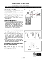
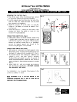
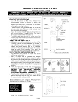
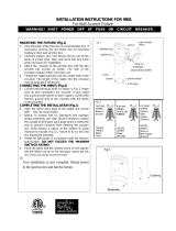
MOUNTING THE FIXTURE (Fig.1)
1. Shut off power at the fuse box or circuit breaker box. If necessary,
remove old fixture and all mounting hardware from wall junction box.
2. Carefully unpack your new fixture and lay out all the parts on a clear
area. Take care not to lose any small parts necessary for installation.
3. Attach the crossbar to the junction box with the two junction box screws
as shown. The side of the crossbar marked “GND” must face out.
4. Thread the nipple part way into the center hole of the crossbar.
5. Connect the wires as described under “Connecting the Wires”.
CONNECTING THE WIRES (Fig.2)
6. Connect the fixture wires to the junction box wires as shown in the Fig. 2.
Make sure all wire connectors are secured and do not easily pull off with
a slight tug. If there is no green ground wire from the junction box,
connect the fixture ground wire to the crossbar with the green screw
provided.
7. To prevent moisture from entering the outlet box and causing a short,
use clear caulking (i.e. Indoor/Outdoor silicone sealant) to outline the
outside of fixture backplate where it meets the wall leaving a space at
bottom to allow moisture a means to escape (Fig.4)
COMPLETING THE INSTALLATION (Fig.1)
8. Place the fixture over the nipple so the nipple protrudes through the
center hole. Holding the fixture in place, thread the cap nut onto the end
of the nipple until fixture is secured to the wall.
9. Install the PL lamp in accordance with the fixture’s specification.
(1×Max26W included). (DO NOT EXCEED THE MAXIMUM WATTAGE
RATING!!)
10. The ballast in each of these models can be replaced by a qualified
electrician without cutting of wires and without damage to the housing,
trim, decorative elements or carpentry to which the fixture is attached.
See installation steps for more detail. The ballast and lamp are
combined, to replace or install, twist pins into socket as shown on Fig.3.
11. Place the glass with the marked arrow on the topside into the fixture.
Then secure the steel bar with screws and plastic washer.
12. This fixture contains an integrated photo sensor that automatically
prevents operation during daylight hours.
13. This fixture is rated for a minimum start temperature of -17° Celsius.
14. This fixture is UL Listed for Wet Location applications.
Your installation is now complete. Return power to the junction box and test
the fixture.
LIMITED 2 YEAR WARRANTY
This Fixture is covered by a Limited 2 year Warranty from the Manufacturer,
effective from the date of purchase. This fixture is warranted against defects
in the quality of the housing, trims, diffuser, shades, and electrical
components. Fixture finishes and/or lamps (bulbs) are expressly excluded
from this warranty; refer to bulb manufacturer for lamp warranty. This
Fixture, if supplied with an automatic shut off sensor, motion control sensor,
or photocell, cannot be installed in conjunction with any other device without
voiding warranty. Modifying this fixture or use of another non-provided
control will also void Product Warranty and UL listing.
II365
SOCKET
TC: TEST POINT 90°C
26W 120V 50/60HZ 84CRI
MAXLITE
MLS26GU 2700K
-
 1
1
the great outdoors by Minka Lavery 9802-144 Installation guide
- Type
- Installation guide
- This manual is also suitable for
Ask a question and I''ll find the answer in the document
Finding information in a document is now easier with AI
Related papers
-
 the great outdoors by Minka Lavery 8282-A61 Installation guide
-
the great outdoors by Minka Lavery 8283-A61 Installation guide
-
The Great Outdoors 8282-A61 User manual
-
The Great Outdoors 8281-A61 User manual
-
 the great outdoors by Minka Lavery 8281-A61 Installation guide
-
 the great outdoors by Minka Lavery 9803-143 Installation guide
-
 the great outdoors by Minka Lavery 9801-144 Installation guide
-
The Great Outdoors 9802-143 User manual
-
 the great outdoors by Minka Lavery 72434-261 Installation guide
-
The Great Outdoors 72400-615B-L User manual
Other documents
-
Minka Group 4802-77 User manual
-
Minka Lavery 348-37B Installation guide
-
 Minka Lavery 564-1 User manual
-
 Minka Lavery 4652-579 User manual
-
 Minka Lavery 4653-579 User manual
-
 Minka Lavery 4653-579 User manual
-
The Great Outdoors 8283-A61 User manual
-
 Minka Lavery 1974-1-138 User manual
-
 Minka Lavery 1974-1-138 User manual
-
Minka-Lavery 893-91-PL User manual


