Page is loading ...

MSC8122/26ADS Reference Manual
MSC8122/26 Application Development System
MSC812xADSRM
Rev B.01, September 2006

Information in this document is provided solely to enable system and software
implementers to use Freescale Semiconductor products. There are no express or
implied copyright licenses granted hereunder to design or fabricate any integrated
circuits or integrated circuits based on the information in this document.
Freescale Semiconductor reserves the right to make changes without further notice
to any products herein. Freescale Semiconductor makes no warranty,
representation or guarantee regarding the suitability of its products for any particular
purpose, nor does Freescale Semiconductor assume any liability arising out of the
application or use of any product or circuit, and specifically disclaims any and all
liability, including without limitation consequential or incidental damages. “Typical”
parameters which may be provided in Freescale Semiconductor data sheets and/or
specifications can and do vary in different applications and actual performance may
vary over time. All operating parameters, including “Typicals” must be validated for
each customer application by customer’s technical experts. Freescale
Semiconductor does not convey any license under its patent rights nor the rights of
others. Freescale Semiconductor products are not designed, intended, or
authorized for use as components in systems intended for surgical implant into the
body, or other applications intended to support or sustain life, or for any other
application in which the failure of the Freescale Semiconductor product could create
a situation where personal injury or death may occur. Should Buyer purchase or use
Freescale Semiconductor products for any such unintended or unauthorized
application, Buyer shall indemnify and hold Freescale Semiconductor and its
officers, employees, subsidiaries, affiliates, and distributors harmless against all
claims, costs, damages, and expenses, and reasonable attorney fees arising out of,
directly or indirectly, any claim of personal injury or death associated with such
unintended or unauthorized use, even if such claim alleges that Freescale
Semiconductor was negligent regarding the design or manufacture of the part.
Freescale™, the Freescale logo, CodeWarrior, and StarCore are trademarks of
Freescale Semiconductor, Inc. All other product or service names are the property
of their respective owners.
© Freescale Semiconductor, Inc. 2004, 2006.
MSC812
xADSRM
Rev. B.01
9/2006
How to Reach Us:
Home Page:
www.freescale.com
Web Support:
http://www.freescale.com/support
USA/Europe or Locations Not Listed:
Freescale Semiconductor, Inc.
Technical Information Center, EL516
2100 East Elliot Road
Tempe, Arizona 85284
+1-800-521-6274 or
+1-480-768-2130
www.freescale.com/support
Europe, Middle East, and Africa:
Freescale Halbleiter Deutschland GmbH
Technical Information Center
Schatzbogen 7
81829 Muenchen, Germany
+44 1296 380 456 (English)
+46 8 52200080 (English)
+49 89 92103 559 (German)
+33 1 69 35 48 48 (French)
www.freescale.com/support
Japan:
Freescale Semiconductor Japan Ltd.
Headquarters
ARCO Tower 15F
1-8-1, Shimo-Meguro, Meguro-ku
Tokyo 153-0064
Japan
0120 191014 or
+81 3 5437 9125
support.japan@freescale.com
Asia/Pacific:
Freescale Semiconductor China Ltd.
Exchange Building 23F
No. 118 Jianguo Road
Chaoyang District
Beijing 100022
China
+86 010 5879 8000
For Literature Requests Only:
Freescale Semiconductor
Literature Distribution Center
P.O. Box 5405
Denver, Colorado 80217
+1-800 441-2447 or
+1-303-675-2140
Fax: +1-303-675-2150
LDCForFreescaleSemiconductor
@hibbertgroup.com

1
2
4
5
6
A
MSC8122/26 ADS Overview
Board Configuration and Installation
ADS Functional Description
ADS Memory Maps and Bus Mapping
ADS Control and Status
ADS Program Information
3
ADS Power and Connectors

1
2
4
5
6
A
MSC8122/26ADS Overview
Board Configuration and Installation
ADS Functional Description
ADS Memory Maps and Bus Mapping
ADS Control and Status
ADS Program Information
3
ADS Power and Connectors

MSC8122/26ADS Reference Manual, Rev. B0.1
Freescale Semiconductor 1
Contents
Contents
About This Book xi
Before Using This Manual—Important Note xi
Audience and Helpful Hints xi
Notational Conventions and Definitions xi
Organization xii
Related MSC8122/26ADS Documentation xiii
Abbreviations and Acronyms xiii
1 MSC8122/26ADS Overview
1.1 MSC8122/26ADS . . . . . . . . . . . . . . . . . . . . . . . . . . . . . . . . . . . . . . . . . . . . . . . . 1-1
1.2 Board Specifications . . . . . . . . . . . . . . . . . . . . . . . . . . . . . . . . . . . . . . . . . . . . . 1-1
1.3 ADS Features . . . . . . . . . . . . . . . . . . . . . . . . . . . . . . . . . . . . . . . . . . . . . . . . . . . 1-2
1.3.1 MSC8122/26ADS Features. . . . . . . . . . . . . . . . . . . . . . . . . . . . . . . . . . . . . . . . 1-3
1.3.2 MSC8103 Features . . . . . . . . . . . . . . . . . . . . . . . . . . . . . . . . . . . . . . . . . . . . . . 1-4
1.3.3 Board Capabilities. . . . . . . . . . . . . . . . . . . . . . . . . . . . . . . . . . . . . . . . . . . . . . . 1-4
2 Board Configuration and Installation
2.1 Hardware Preparation . . . . . . . . . . . . . . . . . . . . . . . . . . . . . . . . . . . . . . . . . . . 2-1
2.1.1 DIP Switches. . . . . . . . . . . . . . . . . . . . . . . . . . . . . . . . . . . . . . . . . . . . . . . . . . . 2-3
2.1.2 ADS Push Buttons. . . . . . . . . . . . . . . . . . . . . . . . . . . . . . . . . . . . . . . . . . . . . . . 2-5
2.1.3 ADS Jumpers. . . . . . . . . . . . . . . . . . . . . . . . . . . . . . . . . . . . . . . . . . . . . . . . . . . 2-6
2.1.3.1 JP1-EE0 for Slave. . . . . . . . . . . . . . . . . . . . . . . . . . . . . . . . . . . . . . . . . . . . . . 2-6
2.1.3.2 JP2-CLKIN for Slave . . . . . . . . . . . . . . . . . . . . . . . . . . . . . . . . . . . . . . . . . . . 2-6
2.1.3.3 JP3-SET MII PHY . . . . . . . . . . . . . . . . . . . . . . . . . . . . . . . . . . . . . . . . . . . . . 2-7
2.1.3.4 JP4-CT-Bus Master Reset Enable . . . . . . . . . . . . . . . . . . . . . . . . . . . . . . . . . 2-7
2.1.3.5 JP5- 8102 Core Power . . . . . . . . . . . . . . . . . . . . . . . . . . . . . . . . . . . . . . . . . . 2-7
2.1.3.6 JP6-Slave Clock Reference . . . . . . . . . . . . . . . . . . . . . . . . . . . . . . . . . . . . . . 2-8
2.1.3.7 JP7-DSI-Ethernet . . . . . . . . . . . . . . . . . . . . . . . . . . . . . . . . . . . . . . . . . . . . . . 2-8
2.1.3.8 JP8-DLL-ON . . . . . . . . . . . . . . . . . . . . . . . . . . . . . . . . . . . . . . . . . . . . . . . . . 2-9
2.1.3.9 JP9-3V3-J3 . . . . . . . . . . . . . . . . . . . . . . . . . . . . . . . . . . . . . . . . . . . . . . . . . . . 2-9
2.1.3.10 JP11-MAC to MAC-enable . . . . . . . . . . . . . . . . . . . . . . . . . . . . . . . . . . . . . . 2-9
2.1.3.11 JP12-Board Slave Voltage Select. . . . . . . . . . . . . . . . . . . . . . . . . . . . . . . . . . 2-9
2.1.3.12 JP13-ADS Power-On-Reset Enable . . . . . . . . . . . . . . . . . . . . . . . . . . . . . . . 2-10
2.1.4 ADS Testing . . . . . . . . . . . . . . . . . . . . . . . . . . . . . . . . . . . . . . . . . . . . . . . . . . 2-10
2.1.4.1 TP13-Slave ClockOut Test Point . . . . . . . . . . . . . . . . . . . . . . . . . . . . . . . . . 2-10
2.1.4.2 JS1-JS4-Current Consumption Measurement . . . . . . . . . . . . . . . . . . . . . . . 2-11
2.1.4.3 JG1-JG5-GND Bridges . . . . . . . . . . . . . . . . . . . . . . . . . . . . . . . . . . . . . . . . 2-11

MSC8122/26ADS Reference Manual, Rev. B0.1
2 Freescale Semiconductor
Contents
2.1.5 ADS LEDs. . . . . . . . . . . . . . . . . . . . . . . . . . . . . . . . . . . . . . . . . . . . . . . . . . . . 2-12
2.2 Installation Options . . . . . . . . . . . . . . . . . . . . . . . . . . . . . . . . . . . . . . . . . . . . . 2-13
2.2.1 Debug Connection Schemes . . . . . . . . . . . . . . . . . . . . . . . . . . . . . . . . . . . . . . 2-13
2.2.2 Standalone Operation . . . . . . . . . . . . . . . . . . . . . . . . . . . . . . . . . . . . . . . . . . . 2-14
2.2.3 Connecting the ADS Board. . . . . . . . . . . . . . . . . . . . . . . . . . . . . . . . . . . . . . . 2-17
3 ADS Power and Connectors
3.1 Power. . . . . . . . . . . . . . . . . . . . . . . . . . . . . . . . . . . . . . . . . . . . . . . . . . . . . . . . . . 3-1
3.1.1 Power Supply . . . . . . . . . . . . . . . . . . . . . . . . . . . . . . . . . . . . . . . . . . . . . . . . . . 3-1
3.1.2 Power Buses . . . . . . . . . . . . . . . . . . . . . . . . . . . . . . . . . . . . . . . . . . . . . . . . . . . 3-3
3.2 Interconnect Signals. . . . . . . . . . . . . . . . . . . . . . . . . . . . . . . . . . . . . . . . . . . . . . 3-4
3.2.1 Stereo Phone Jack Connectors . . . . . . . . . . . . . . . . . . . . . . . . . . . . . . . . . . . . . 3-5
3.2.2 SMB Connector. . . . . . . . . . . . . . . . . . . . . . . . . . . . . . . . . . . . . . . . . . . . . . . . . 3-5
3.2.3 Logic Analyzer Connectors. . . . . . . . . . . . . . . . . . . . . . . . . . . . . . . . . . . . . . . . 3-5
3.2.4 Mezzanine Header Ethernet Connectors. . . . . . . . . . . . . . . . . . . . . . . . . . . . . . 3-6
3.2.5 RJ45 E1/T1 Line Connector . . . . . . . . . . . . . . . . . . . . . . . . . . . . . . . . . . . . . . . 3-6
3.2.6 Slave UART Port Connector. . . . . . . . . . . . . . . . . . . . . . . . . . . . . . . . . . . . . . . 3-6
3.2.7 Altera’s In-System Programming (ISP) Connector . . . . . . . . . . . . . . . . . . . . . 3-7
3.2.8 Host Debug EOnCE (SYS) Connector . . . . . . . . . . . . . . . . . . . . . . . . . . . . . . . 3-7
3.2.9 EE1 Connector . . . . . . . . . . . . . . . . . . . . . . . . . . . . . . . . . . . . . . . . . . . . . . . . . 3-9
3.2.10 Ethernet Port Connectors . . . . . . . . . . . . . . . . . . . . . . . . . . . . . . . . . . . . . . . . . 3-9
3.3 ADS Expansion Connectors . . . . . . . . . . . . . . . . . . . . . . . . . . . . . . . . . . . . . . 3-10
3.3.1 Expansion Connector J1 . . . . . . . . . . . . . . . . . . . . . . . . . . . . . . . . . . . . . . . . . 3-10
3.3.2 Expansion Connector J2 . . . . . . . . . . . . . . . . . . . . . . . . . . . . . . . . . . . . . . . . . 3-10
3.3.3 Expansion Connector J3 . . . . . . . . . . . . . . . . . . . . . . . . . . . . . . . . . . . . . . . . . 3-11
3.3.4 Expansion Connector J4 . . . . . . . . . . . . . . . . . . . . . . . . . . . . . . . . . . . . . . . . . 3-11
3.3.5 Expansion Connector J5 . . . . . . . . . . . . . . . . . . . . . . . . . . . . . . . . . . . . . . . . . 3-11
4 ADS Functional Description
4.1 MSC8122/26ADS Block Diagram. . . . . . . . . . . . . . . . . . . . . . . . . . . . . . . . . . . 4-1
4.2 Reset and Reset-Configuration. . . . . . . . . . . . . . . . . . . . . . . . . . . . . . . . . . . . . 4-3
4.2.1 Power-On-Reset . . . . . . . . . . . . . . . . . . . . . . . . . . . . . . . . . . . . . . . . . . . . . . . . 4-3
4.2.2 Host Power-On-Reset Configuration . . . . . . . . . . . . . . . . . . . . . . . . . . . . . . . . 4-3
4.2.3 Slave Power-On-Reset Configuration. . . . . . . . . . . . . . . . . . . . . . . . . . . . . . . . 4-4
4.2.4 Hard/Soft Reset Capabilities. . . . . . . . . . . . . . . . . . . . . . . . . . . . . . . . . . . . . . . 4-4
4.2.5 Hard Reset Configuration . . . . . . . . . . . . . . . . . . . . . . . . . . . . . . . . . . . . . . . . . 4-5
4.2.6 Host Hard Reset Configuration. . . . . . . . . . . . . . . . . . . . . . . . . . . . . . . . . . . . . 4-5
4.2.7 Slave Reset Configuration. . . . . . . . . . . . . . . . . . . . . . . . . . . . . . . . . . . . . . . . . 4-7
4.3 Clock Source. . . . . . . . . . . . . . . . . . . . . . . . . . . . . . . . . . . . . . . . . . . . . . . . . . . 4-11
4.3.1 Host Main Clock Scheme . . . . . . . . . . . . . . . . . . . . . . . . . . . . . . . . . . . . . . . . 4-11

MSC8122/26ADS Reference Manual, Rev. B0.1
Freescale Semiconductor 3
Contents
4.3.2 Slave Main Clock Scheme . . . . . . . . . . . . . . . . . . . . . . . . . . . . . . . . . . . . . . . 4-12
4.4 60x Bus Buffering and Multiplexing . . . . . . . . . . . . . . . . . . . . . . . . . . . . . . . 4-13
4.4.1 60x-Compatible System Bus User Instructions . . . . . . . . . . . . . . . . . . . . . . . 4-15
4.5 Chip Select Designation. . . . . . . . . . . . . . . . . . . . . . . . . . . . . . . . . . . . . . . . . . 4-18
4.6 Interrupts . . . . . . . . . . . . . . . . . . . . . . . . . . . . . . . . . . . . . . . . . . . . . . . . . . . . . 4-19
4.6.1 Host-Side Interrupts . . . . . . . . . . . . . . . . . . . . . . . . . . . . . . . . . . . . . . . . . . . . 4-19
4.6.1.1 ABORT Interrupt to MSC8103 . . . . . . . . . . . . . . . . . . . . . . . . . . . . . . . . . . 4-19
4.6.1.2 Slave Interrupt . . . . . . . . . . . . . . . . . . . . . . . . . . . . . . . . . . . . . . . . . . . . . . . 4-19
4.6.1.3 Flash Ready Interrupt . . . . . . . . . . . . . . . . . . . . . . . . . . . . . . . . . . . . . . . . . . 4-20
4.6.1.4 Fast Ethernet PHY Interrupt. . . . . . . . . . . . . . . . . . . . . . . . . . . . . . . . . . . . . 4-20
4.6.2 Slave-Side Interrupts. . . . . . . . . . . . . . . . . . . . . . . . . . . . . . . . . . . . . . . . . . . . 4-20
4.6.2.1 ABORT Interrupt to MSC8122/26. . . . . . . . . . . . . . . . . . . . . . . . . . . . . . . . 4-21
4.6.2.2 TSI Interrupt. . . . . . . . . . . . . . . . . . . . . . . . . . . . . . . . . . . . . . . . . . . . . . . . . 4-21
4.6.2.3 FALC56 Interrupt. . . . . . . . . . . . . . . . . . . . . . . . . . . . . . . . . . . . . . . . . . . . . 4-21
4.6.2.4 Flash Ready Interrupt . . . . . . . . . . . . . . . . . . . . . . . . . . . . . . . . . . . . . . . . . . 4-21
4.6.2.5 MSC8122/26 RMII/MII Fast Ethernet PHY Interrupt. . . . . . . . . . . . . . . . . 4-21
4.6.2.6 MSC8122/26 Fast Ethernet Switch Interrupt . . . . . . . . . . . . . . . . . . . . . . . . 4-21
4.7 SDRAM. . . . . . . . . . . . . . . . . . . . . . . . . . . . . . . . . . . . . . . . . . . . . . . . . . . . . . . 4-22
4.7.1 SDRAM Programming . . . . . . . . . . . . . . . . . . . . . . . . . . . . . . . . . . . . . . . . . . 4-23
4.7.2 SDRAM Refresh . . . . . . . . . . . . . . . . . . . . . . . . . . . . . . . . . . . . . . . . . . . . . . . 4-24
4.8 Flash . . . . . . . . . . . . . . . . . . . . . . . . . . . . . . . . . . . . . . . . . . . . . . . . . . . . . . . . . 4-24
4.9 TDM Port Peripherals. . . . . . . . . . . . . . . . . . . . . . . . . . . . . . . . . . . . . . . . . . . 4-25
4.9.1 Time Slot Interchanger (TSI) . . . . . . . . . . . . . . . . . . . . . . . . . . . . . . . . . . . . . 4-26
4.9.2 E1/T1 Framer . . . . . . . . . . . . . . . . . . . . . . . . . . . . . . . . . . . . . . . . . . . . . . . . . 4-27
4.9.3 CODEC . . . . . . . . . . . . . . . . . . . . . . . . . . . . . . . . . . . . . . . . . . . . . . . . . . . . . . 4-27
4.9.3.1 CODEC Initialization. . . . . . . . . . . . . . . . . . . . . . . . . . . . . . . . . . . . . . . . . . 4-27
4.10 MSC8122/26 SMII/RMII/MII Fast Ethernet Switches . . . . . . . . . . . . . . . . 4-29
4.10.1 Switching Ethernet Modes . . . . . . . . . . . . . . . . . . . . . . . . . . . . . . . . . . . . . . . 4-30
4.10.2 Fast Ethernet Clocking Modes . . . . . . . . . . . . . . . . . . . . . . . . . . . . . . . . . . . . 4-32
4.11 MSC8122/26 I2C . . . . . . . . . . . . . . . . . . . . . . . . . . . . . . . . . . . . . . . . . . . . . . . 4-33
4.12 RS-232 Transceivers . . . . . . . . . . . . . . . . . . . . . . . . . . . . . . . . . . . . . . . . . . . . 4-34
4.13 Slic-Slac Interface Support . . . . . . . . . . . . . . . . . . . . . . . . . . . . . . . . . . . . . . . 4-36
4.14 Packet Peripherals (Host-Side). . . . . . . . . . . . . . . . . . . . . . . . . . . . . . . . . . . . 4-37
4.14.1 10/100 T-Base Ethernet PHY . . . . . . . . . . . . . . . . . . . . . . . . . . . . . . . . . . . . . 4-37
5 ADS Memory Maps and Bus Mapping
5.1 Memory Maps . . . . . . . . . . . . . . . . . . . . . . . . . . . . . . . . . . . . . . . . . . . . . . . . . . 5-1
5.1.1 Host 60x Bus Mapping . . . . . . . . . . . . . . . . . . . . . . . . . . . . . . . . . . . . . . . . . . . 5-1
5.1.2 Slave System Bus Mapping. . . . . . . . . . . . . . . . . . . . . . . . . . . . . . . . . . . . . . . . 5-5
5.2 Host Memory Controller Registers Programming . . . . . . . . . . . . . . . . . . . . . 5-7
5.2.1 Host Machine A/B Mode Registers . . . . . . . . . . . . . . . . . . . . . . . . . . . . . . . . . 5-9

MSC8122/26ADS Reference Manual, Rev. B0.1
4 Freescale Semiconductor
Contents
5.3 Slave Memory Controller Registers Programming . . . . . . . . . . . . . . . . . . . 5-11
5.3.1 Slave Machine A/C Mode Registers Programming . . . . . . . . . . . . . . . . . . . . 5-13
5.4 Expansion Connectors. . . . . . . . . . . . . . . . . . . . . . . . . . . . . . . . . . . . . . . . . . . 5-15
5.4.1 60x Bus Expansion Connector J1 . . . . . . . . . . . . . . . . . . . . . . . . . . . . . . . . . . 5-15
5.4.2 60x Bus Expansion Connector J2 . . . . . . . . . . . . . . . . . . . . . . . . . . . . . . . . . . 5-19
5.4.3 MSC8122/26 Expansion Connector J3 . . . . . . . . . . . . . . . . . . . . . . . . . . . . . . 5-22
5.4.4 H.110 Bus Expansion Connector J4 . . . . . . . . . . . . . . . . . . . . . . . . . . . . . . . . 5-24
5.4.5 MSC8122/26 (Slic-Slac) Expansion Connector J5. . . . . . . . . . . . . . . . . . . . . 5-27
6 ADS Control and Status
6.1 Board Control and Status Registers. . . . . . . . . . . . . . . . . . . . . . . . . . . . . . . . . 6-1
6.1.1 Board Control/Status Register 0 (BCSR0) . . . . . . . . . . . . . . . . . . . . . . . . . . . . 6-3
6.1.2 Board Control/Status Register 1 (BCSR1) . . . . . . . . . . . . . . . . . . . . . . . . . . . . 6-4
6.1.3 Board Control/Status Register 2 (BCSR2) . . . . . . . . . . . . . . . . . . . . . . . . . . . . 6-4
6.1.4 Board Control/Status Register 3 (BCSR3) . . . . . . . . . . . . . . . . . . . . . . . . . . . . 6-6
6.1.5 Board Control/Status Register 4 (BCSR4) . . . . . . . . . . . . . . . . . . . . . . . . . . . . 6-7
6.1.6 Board Control/Status Register Identification 5 (BCSR5) . . . . . . . . . . . . . . . . . 6-8
6.1.7 Board Control/Status Register Miscellaneous 6 (BCSR6) . . . . . . . . . . . . . . . . 6-9
6.1.8 Board Control/Status Register Miscellaneous 7 (BCSR7) . . . . . . . . . . . . . . . 6-10
6.1.9 Board Control/Status Register Miscellaneous 8 (BCSR8) . . . . . . . . . . . . . . . 6-11
6.1.10 Board Control/Status Register Ethernet 9 (BCSR9). . . . . . . . . . . . . . . . . . . . 6-12
6.1.11 Board Control/Status Register Miscellaneous 10 (BCSR10) . . . . . . . . . . . . . 6-13
A Program Information
A.1 MSC8102/22/26ADS CPLD Code. . . . . . . . . . . . . . . . . . . . . . . . . . . . . . . . . . .A-1
A.2 MSC8122/26ADS CPLD Code . . . . . . . . . . . . . . . . . . . . . . . . . . . . . . . . . . . .A-34

MSC8122/26ADS Reference Manual, Rev. B0.1
Freescale Semiconductor xi
About This Book
This user’s guide describes engineering specifications for the MSC8122/26 application
development system (ADS) board. The MSC8122/26ADS board targets either the StarCore
®
based MSC8122 or the MSC8126 processor. Each of these is a highly integrated system-on-a-chip
device containing four StarCore SC140 digital signal processing (DSP) cores.
The MSC8122/26ADS board is intended to serve as a platform for software development for the
Starcore processor environment. This manual lists and explains various features of the
MSC8122/26ADS and describes how the board must be configured to develop and communicate
code for each processor.
Before Using This Manual—Important Note
The information in this manual is subject to change without notice, as described in the
disclaimers on the title page of this manual. Before using this manual, determine whether it is the
latest revision and whether there are errata or addenda. To locate any published errata or updates
associated with this manual or this product, refer to the world-wide web site listed on the back
cover of this manual or call your local distributor or sales representative.
Audience and Helpful Hints
This manual is for software developers and applications programmers who are developing
products using the Starcore MSC8122 or MSC8126 device.
Notational Conventions and Definitions
This manual uses the following notational conventions:
mnemonics Instruction mnemonics appear in lowercase bold.
italics Book titles in text are set in italics. In addition, italics are used for
emphasis and to highlight the main items in bulleted lists. Variables and
equations are also italicized.
0x Prefix to denote a hexadecimal number.
0b Prefix to denote a binary number.

MSC8122/26ADS Reference Manual, Rev. B0.1
xii Freescale Semiconductor
Organization
Following is a summary and a brief description of the chapters of this manual:
Chapter 1, MSC8122/26ADS Overview. Descriptive overview of main board
specifications, MSC8103 and MSC8122/26ADS features.
Chapter 2, Board Configuration and Installation. Lists and explains necessary dipswitch
and jumper configurations, test points and bridges, functional LEDs, as well as describing
installation options such as debug connection schema and standalone operation. Also
gives brief instructions on how to connect the board.
Chapter 3, ADS Power and Connectors. Device operating modes as determined by PLL
settings, reset sources, PLL initialization example, and the system boot sequence.
Chapter 4, ADS Functional Description. Describes the ADS memory map, memory
mapping for host and slave buses, and how they may be controlled.
Chapter 5, ADS Memory Maps and Bus Mapping. Describes board power connector,
supply and buses. Describes all board peripheral connectors and expansion connectors.
Explains the mapping of the expansion connector buses.
Chapter 6, ADS Control and Status. Describes the ADS control and status registers and
their programming.
Appendix A, Program Information. Gives code listings for each version of the BCSR
code contained in the ADS board CPLD.
REG[FIELD] Abbreviations or acronyms for registers appear in uppercase text.
Following the register name, the bit or field name is enclosed in
brackets. For example, ICR[8]:INIT refers to the Force Initialization bit
(bit 8) in the host Interface Control Register.
Active high
signals
Names of active high signals appear in small caps, sans serif, as follows:
SIO1D[0–63], SIO1R, and GND
PA
.
Active low
signals
Signal names of active low signals appear in small capital letters in a
sans serif typeface, with an overbar:
SIOP1CS, SIOP1WE[0–1], and
SIOP1HT0.
x A lowercase italicized x in a register or signal name indicates that there
are multiple registers or signals with this name. For example,
SIOxA
refers to the
SIO0A and SIO1A signals. MxCBCR refers to the M0CBCR
and M1CBCR registers.

MSC8122/26ADS Reference Manual, Rev. B0.1
Freescale Semiconductor xiii
Related MSC8122/26ADS Documentation
MSC8122 Reference Manual
MSC8126 Reference Manual
MSC8122 Reference Manual
MSC8126 Reference Manual
MSC8102 Technical Data sheet
MSC8103 Technical Data sheet
MSC8122 Technical Data sheet
MSC8126 Technical Data sheet
SWITI Switching Device PEF24471 HTSI-XL Wired Communication Data sheet
VIA Technologies VT6525A SMII Switch Data sheet
VIA Technologies VT6510B RMII Switch Data sheet
Abbreviations and Acronyms
List of abbreviations and acronyms:
ADS - Application Development System
ALU - Arithmetic Logic Unit
BCSR - Board Control and Status Register
CPM - Communication Processor Module
CW - CodeWarrior® IDE for StarCore
DIP - Dual-In-Line Package
DMA - Direct Memory Access
DSI - Direct Slave Interface
DSP - Digital Signal Processor
EOnCE - Enhanced On-Chip Emulation
GPCM - Memory Controller General Purpose Chip-select Machine
GPL - General Purpose Line (associated with a UPM)
HCW - Hardware Configuration Word
MII - Media Independent Interface
PHY - Physical Layer

MSC8122/26ADS Reference Manual, Rev. B0.1
xiv Freescale Semiconductor
RMII - Reduced Media Independent Interface
SDRAM Machine - Memory Controller Synchronous Dynamic RAM Machine
SIU - System Interface Unit
SMII - Serial Media Independent Interface
TDM - Time Division Multiplex
UART - Universal Asynchronous Receiver Transmitter
UPM Machine - (Memory Controller) User Programmable Machine
ZD - Clock Zero Delay Buffer with internal PLL for skew elimination

MSC8122/26ADS Reference Manual, Rev. B0.1
Freescale Semiconductor 1-1
MSC8122/26ADS Overview 1
The MSC8122/26ADS is based on the proven technology of the older MSC8102ADS. It
functions just as its predecessor did and the software created using it is backwards compatible to
the MSC8102, within chip limitations. The MSC8122/26ADS is identifiable by the sticker on the
Altera BSCR chip, a customer programmable logic device (CPLD) in socket U38, which should
indicate that the code contained is for the MSC8122/26ADS board. The processor in U15 can be
identified as either MSC8122 or MSC8126 by a label affixed to cPCI connector J5, which is also
the Slic-Slac connector.
1.1 MSC8122/26ADS
This manual describes engineering specifications for the MSC8122/26ADS. This applications
development system (ADS) board targets the StarCore MSC8122 or MSC8126 chip. Each is a
highly integrated system-on-a-chip device containing four StarCore SC140 digital signal
processor (DSP) cores.
The MSC8122/26ADS board is intended to serve as a platform for software development for the
MSC8122/26 processor environment. On-board resources and associated debugger enable
developers to perform a variety of tasks: download and run code; set breakpoints; display
memory and registers, and connect proprietary hardware via the expansion connectors. The
MSC8122/26 processor enables incorporation of these features into selected systems.
In addition, the MSC8122/26ADS may be used as a demonstration tool. For example, application
software may be burned into the flash memory of the ADS and run in exhibitions.
1.2 Board Specifications
Specifications for the MSC8122/26ADS board are provided in Table 1-1.
Table 1-1. MSC8122/26ADS Specifications
Characteristics Specifications
Power requirements. 9-18V external DC power supply or RACK 12V supply for
12V max current 1.8A.
MSC8122/26ADS multicore (4xSC140 core) DSP. Internal clock runs up to 500MHz @ 1.2V for the
MSC8122/26.
MSC8103 (host-side) 60x bus (DSI). MSC8103 60x bus running up to 100 MHz clock frequency.

MSC8122/26ADS Reference Manual, Rev. B0.1
1-2 Freescale Semiconductor
MSC8122/26ADS Overview
1.3 ADS Features
The MSC8122/26ADS is based on 64-bit MSC8122 or MSC8126 chips. The system bus runs up
to 166MHz for the MSC8122/26. The direct slave interface (DSI) bus runs up to 100MHz. The
host controller MSC8103 and the 60x-bus interface with the slave MSC8122/26 and its DSI bus.
MSC8122/26 (slave-side) System bus. ADS system bus running clock frequencies up to 166 MHz
for the MSC8122/26
MSC8122/26 (slave-side) DSI bus. MSC8122/26 DSI bus running up to 100 MHz
MSC8103:
PowerPC (60x) bus:
Local Bus:
Addressing:
Data Bus Width:
MSC8122/26 DSI bus (non-buffered)
SDRAM 100MHz soldered (non-buffered)
Flash memory (buffered)
BCSR (buffered)
MSC8122/26 System Bus:
Addressing:
SDRAM 200MHz (166M Bus) soldered (non-buffered)
64-bit configuration - 16MB organized on two devices 4bank
x 512K x 32-bit.
32-bit configuration - 8MB organized on one device 4bank x
512K x 32-bit.
Flash memory (buffered)
4GB (32 address lines) @ 64bit Data
External Decoding: 16MB (24 address lines)
Internal Decoding: 4GB (32 address lines)
64-bit
2MB organized as 32-bit (default conf.) or 64-bit
16MB,organized on two devices 4Bank x 512K x 32-bit
4MB, 16-bits wide
BCSR contains eleven byte-size registers
64/32-bit - dependant upon the configuration mode
4GB (32 address lines)
16MB organized on two devices 4Bank x 512K x 32-bit
8MB on one device 4Bank x 512K x 32-bit
4MB organized 4Meg x 8-bit
Operating temperature.
0
O
C - 30
O
C (room temperature)
Storage temperature.
-25
O
C to 85
O
C
Relative humidity. 5% to 90% (non-condensing)
Dimensions require 6U CompactPCI® form factor with:
Length
Width
Thickness
C.S. Height
P.S Height
233.35 mm
160.0 mm
1.8 mm
17 mm
1.9 mm
Table 1-1. MSC8122/26ADS Specifications (Continued)
Characteristics Specifications

ADS Features
MSC8122/26ADS Reference Manual, Rev. B0.1
Freescale Semiconductor 1-3
1.3.1 MSC8122/26ADS Features
The MSC8122/26ADS features are as follows:
• The DSI bus is a slave of the MSC8103 (with its 60x bus). This host controls the
extended DSI address bus HA7-HA29 for MSC8122/26.
• The DSI is configurable to 32-bit when the system bus is 64-bit (default mode) or
vice versa (DSI 64-bit/System bus 32-bit) or DSI 32-bit/System 32-bit/Ethernet.
• A Memory-Controller synchronous dynamic RAM (SDRAM) machine controls
SDRAM memory size (32MB, 16MB, or 8MB on new boards) on the system bus.
Memory size is dependant on the system bus configuration.
• The ADS features a 4MB @ 8-bit size Flash for configuration/boot/program
storage.
• Four MSC8122/26 TDM ports connect to an Infineon TSI PEF24471 device. This
device allows interconnecting of T1/E1 time-slots between Infineon FALC
PEB2256 and Dual CODEC MT92303. It is possible to interface with H.110 TDM
bus on the ADS J4 Compact PCI connector.
• An RS-232 Transceiver MAX3241 supports the universal asynchronous
receiver/transmitter (UART) port operation of the MSC8122/26.
• A FETH PHY REALTEK RTL8208 supports SMII and enables MAC2PHY with
the MSC8122/26 TDM/Ethernet multiplexed pins.
• A FETH PHY Davicom DM9161A supports RMII/MII and enables MAC2PHY
with MSC8122/26 TDM/Ethernet multiplexed pins or DSI/Ethernet multiplexed
pins.
• A FETH switch on the mezzanine board supports SMII, based on VIA VT6526A
that can boot from on-board I
2
C EEPROM and enables MAC2MAC with
MSC8122/26 TDM/Ethernet multiplexed pins. FETH MII-PHY populated.
• FETH switch on mezzanine board supports RMII based on VIA VT6510B that can
boot from on-board I
2
C EEPROM. Enables MAC2MAC with MSC8122/26
TDM/Ethernet multiplexed pins or DSI/Ethernet multiplexed pins. FETH
MII-PHY populated.
• MSC8122/26 Core power supply 0.9 - 2.0V set by potentiometer.

MSC8122/26ADS Reference Manual, Rev. B0.1
1-4 Freescale Semiconductor
MSC8122/26ADS Overview
1.3.2 MSC8103 Features
The MSC8103 features are as follows:
• Acts as host for the MSC8122/26.
• On-board buffers disconnect MSC8103 from Slave-cPCI bus.
• SDRAM machine controls 16MB SDRAM on 60x bus.
• Features a 4MB @16-bit size Flash for configuration/boot/program storage.
• Communication processor module (CPM) ports are connected to 10/100 Base-T
PHY Davicom (FCC2) and RS-232 Transceiver MAX3241(SCC1).
• An 8-bit Board Control and Status Register (BCSR) is required for ADS
configuration.
1.3.3 Board Capabilities
The MSC8122/26ADS board capabilities are as follows:
• MSC8122/26 TDM/Ethernet or DSI/Ethernet pins connect MAC2MAC with FCC2
of the MSC8103.
• Programmable hard reset configuration for MSC8122/26 is executed from the
Flash memory or the DSI bus; but, may also be forced from the BCSR.
• Boot MSC8122/26 from the host controller (via the DSI bus) or the system bus
(Flash); but, can also be performed from the UART or TDM ports or I
2
C
EEPROM.
•I
2
C bootable EEPROM for MSC8122/26 and/or MSC8103 in I
2
C multi-master
configuration (Fairchild FM24C256FLEN - 2 x 32KB). Additional I
2
C EEPROM
on the Mezzanine Ethernet switch found on the same I
2
C bus.
• High density logic analyzer connectors (MICTOR) facilitate measurement of
MSC8122/26 signals. MSC8122/26 mictors reside on the buffered system bus
enable measurments with special mode via buffers.
• As expansion connectors, PICMG2.16 CompactPCI® connector J3 transfers
SMII/RMII/MII data from the MSC8122/26 Ethernet controller.
• MAX4372 Current-Sense Amplifier with voltage output supplies current
measurement capability for MSC8122/26 PLL/IO/CORE power.
• Debugging performed via an external command converter connected to an
enhanced on-chip emulation (EOnCE) 14-pin header. Debug through an external
add-on board Command Converter via a parallel port connected to cPCI-J3
connector.
• Buffers disconnect MSC8103 from 60x bus thus enabling host from rack for the
MSC8122/26.

ADS Features
MSC8122/26ADS Reference Manual, Rev. B0.1
Freescale Semiconductor 1-5
• Via the backplane, the EOnCE debug chain allows the connection of additional
ADS boards.
• Debug option is available in standalone mode (board on table) via the J3 connector.
This enables EPP connection through an add-on connector with buffer to interface
the PC parallel port.
• Select debug enable/disable and request options after reset. Processor EE pins
enable and support noted options.
• Board identification and status can be read via the BCSR.
• Connect external pulse generator to MSC8122/26 clock input via the SMB-form
RF-connector.
• Board configurations are available via the dual-in-line package (DIP) switch
setting.
• Board features buttons for host and slave: Power-On-Reset, soft reset, hard reset,
and abort.
• Board powered by a single 9-18V external DC supply with on-board reverse
polarity protection.
• Board DC-DC SIP converters provided with input voltage. First converter
parameters: 3.3V @ 16A 1%. Second converter parameters: 0.9-2.0V @ 16A or
10A or 5A (Depending on assemblly) 1%.
• First DC-DC converter powers board’s 3.3V I/O and MSC8103 1.6V linear voltage
regulator. Second converter powers MSC8122/26 core voltage. Potentiometer used
to adjust voltage supplied by the converter to the board.
• Slic-Slac interface (via the rack) enables use of a 6-line communication board
based on Voice-over-Broadband SLIC-SLAC™ chip set that implements a
two-channel universal telephone line interface.
• SW option switch provides ten SW options controlled via BCSR.
• LEDs indicate power supply, peripheral enables, EE1-pin status and software
signals.

MSC8122/26ADS Reference Manual, Rev. B0.1
1-6 Freescale Semiconductor
MSC8122/26ADS Overview

MSC8122/26ADS Reference Manual, Rev. B0.1
Freescale Semiconductor 2-1
Board Configuration and Installation 2
This chapter contains configuration and installation information for the MSC8122/26ADS board.
The user can check the configuration of the ADS board against the factory settings shown in this
manual to ensure proper board functionality.
Caution: Ensure that power is off or disconnected prior to reconfiguring an
installed ADS board. Reconfiguring jumpers with the power on may
damage system circuits.
2.1 Hardware Preparation
The first step in preparing the hardware is to unpack the ADS board. When unpacking the
MSC8122/26ADS board from its shipping carton refer to the packing list to verify that all items
are present and in good condition.
Note: If the ADS board arrives damaged, save all packing material and contact the carrier’s
agent.
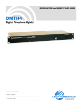
The location of MSC8122/26ADS board parts is shown in Figure 2-1.

MSC8122/26ADS Reference Manual, Rev. B0.1
2-2 Freescale Semiconductor
Board Configuration and Installation
Figure 2-1. MSC8122/26ADS Top-side Part Location Diagram
41.5
Mhz
50
Mhz
U38
CPLD Code
U39
MSC8103
U1
JP3
JP2
JP1
TP13
JP6
JP5
JP4
JP7
JP10
JP12
JP11
JP13
SW4
SW5 SW6 SW7
MSC
8122
U19
P1
P5
P6
P8
P10
P14
P16
P17
P22
P24
SW8
SW9 SW10 SW11 SW12
PRESET
I---------HOST-----------i
I----------SLAVE------------i
SW1 SW2 SW3
Mezzanine
Mezzanine
Hreset
Sreset
Abort
J5
J4
J3
J2
J1
LEDs
LEDs
LEDs
RP1
RP2
P11
P12
P13
P15
P18
P19
P20
P9
P7
P3
P4
P21
JP9
JP8
/