York CYK Compound Centrifugal Chiller User guide

Type
User guide

York CYK Compound Centrifugal Chiller: a robust solution for specialized cooling demands. With the ability to operate in extreme conditions, this chiller handles applications where standard chillers struggle. Ideal for air-cooled radiators, brine chilling, and heat pumps, it's designed to meet unique cooling challenges.

York CYK Compound Centrifugal Chiller: a robust solution for specialized cooling demands. With the ability to operate in extreme conditions, this chiller handles applications where standard chillers struggle. Ideal for air-cooled radiators, brine chilling, and heat pumps, it's designed to meet unique cooling challenges.

The High-Head
Performance Solution
Ma xE
CYK
CENTRIFUGaL CHILLERS
Performance where standard chillers can’t compete
The M
a x E
CYK centrifugal chiller incorporates a design
using two centrifugal compressors arranged in series to
handle air-cooled, brine-chilling, and heat-pump applications
at conditions outside the range of typical centrifugal chillers.
These units use the same technology employed in the renowned
line of M
a x E single-stage centrifugal chillers. Using HFC-134a,
M
a x E CYK chillers are available in a wide range of capacities:
For air-cooled applications (air-cooled radiators): 700 to
2,300 TR at 44°F LWT (2,500 to 8,100 kWR at 7°C LWT)
For brine chilling: 700 to 1,600 TR at 20°F LBT (2,500 to
5,600 kWR at -7°C LBT)
For heat pump applications: 11,000 to 38,000 MBH at 155°F
(maximum output temperature) 3,200 to 11,000 kWR at 68°C
(maximum output temperature)
The combination of standard components and unique
performance characteristics make M
a x E CYK chillers the
technology of choice for jobs where standard chiller designs
can’t compete. Compound-system technology provides
energy and performance advantages for utilities, institutions,
and commercial facilities.
Understanding high-head applications
Certain job-site conditions require chillers to operate beyond
the limits found in typical air-conditioning applications. These
extreme conditions are characterized by leaving chilled uid
temperatures below 36°F (2°C), leaving condensing uid
temperatures above 105°F (41°C), or a combination of both.
When the leaving chilled uid or leaving condenser uid
temperature exceeds standard limits, the lift on the
compressor increases dramatically. The compressor must
develop higher differential pressure on the refrigerant gas in
the compression phase, which results in higher head pressure.
Handling applications
when the pressure is on
TYPICAL CHILLER OPERATING RANGE
Leaving chilled and condenser water temperatures compound
chillers operate beyond the range of standard chillers.
2
High-head conditions are found in three typical
cooling applications:
1) Air-cooled radiators for water chilling in locations that
lack water for condensing.
2) Brine chilling for ice-thermal-storage applications and
for light industrial-refrigeration jobs.
3) Heat pumps for producing hot water with
simultaneous chilling.
High compressor head in brine applications is due to lower
evaporator temperature and pressure conditions. In heat-
pump and air-cooled-radiator projects, it’s due to very high
condenser refrigerant temperature and pressure conditions.
The chiller designed for high-head conditions
Typical air-conditioning chillers are designed within the limits
of the available compression ratio of the compressor. These
limits are quickly exceeded by the unique differential pressures
encountered in high-head applications.
The M
a x E CYK chiller overcomes these compressor-design
challenges by using the principle of compounding. A compound
design arranges two individual compressors in series. By owing
the refrigerant gas through two compressors, the pressure ratio
becomes the sum of the two individual centrifugal compression
ratios. The result is a much higher total lift pressure available
to the system, which is able to handle the high head
demanded by extreme conditions.
Benefits of compressor compounding
Standard components: Each M
a x E CYK chiller employs
common parts instead of a one-of-a-kind design. The
compressors and heat exchangers use standard technology
proven in the successful M
a x E packaged chiller line. Each
compressor is driven by a standard, open-drive, electric motor.
Compact footprint: Compressors and motors are mounted above
the shells to assure the smallest footprint for this type of chiller.
Greater adaptability: With the M
a x E CYK chiller, the impeller
diameter, width and speed can be optimized for each stage
of compression based on operating conditions.
3
The principal of compounding two compressors operate
in series with a common refrigerant circuit.
Comp 2
Comp 1
Superior part-load performance: Using a compound
arrangement allows the use of pre-rotation-vane (PRV) capacity
control for the centrifugal impellers of both compressors.
Pre-rotation vanes act like a throttle on the suction side of the
compressor to control compressor load. With PRV control on
both compressors, the result is better off-design performance
than for typical multistage compressors.
Handles varying condensing conditions: Since chillers spend
most of their time operating at off-design conditions, off-design
performance is a major factor in the energy-saving equation.
A compound chiller can operate with a wider range of
condensing-water temperatures than typical chillers. The
M
a x E CYK chiller unit allows one compressor to be shut off,
so the chiller can run on just one compressor during low-head
conditions. This practice not only ensures system stability, it
allows the chiller to run more efciently and takes advantage
of cooling-water temperatures well below design.
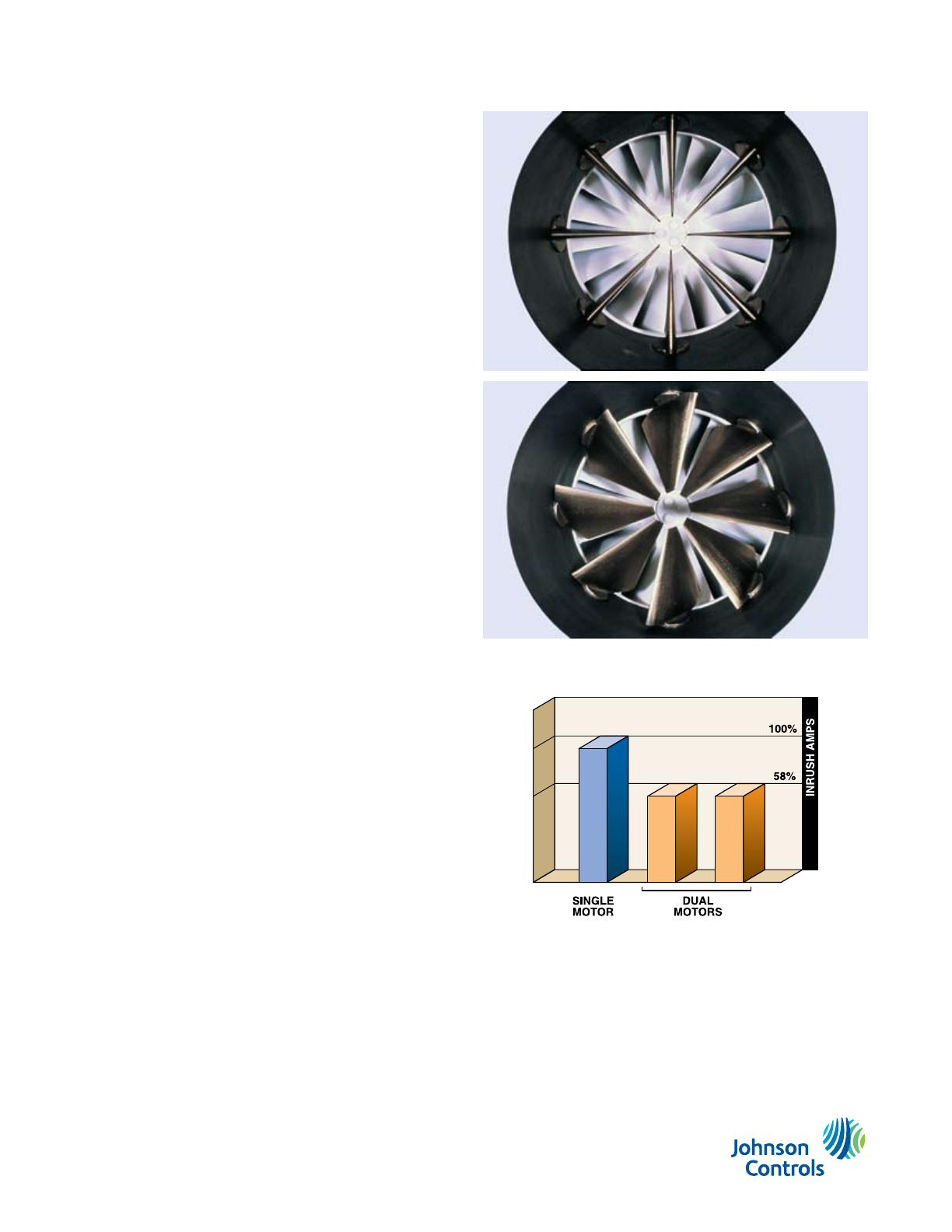
Lower inrush current: Instead of starting a single, large motor,
the M
a x E CYK chiller stagger-starts the motors in sequence.
Consequently, peak inrush current is reduced to about 58%
compared to starting a motor for a single, large compressor.
Lower sound levels: Acoustically, with compound compressors
sharing the workload, compressor RPMs are lower than in
standard centrifugal designs — and lower RPMs help lower
sound levels.
Economizer option: An optional economizer is available to
further improve cycle efficiency for lower energy consumption.
Built-in reliability
An on-board control panel simplies operation by managing
the staggered-start sequence of the compressors. The colored
graphical operator interface clearly displays operating
parameters, setpoints and alarms for quick response.
M
a x E CYK chillers operate with environmentally responsible
HFC-134a refrigerant with zero ozone-depletion potential,
which eliminates chiller downtime for retrofit or replacement.
To further assure reliable performance, each M
a x E chiller
is assembled at the factory. As an option, the unit can be
run-tested at design conditions prior to shipment.
For more information on innovative products designed
specifically for applications that are beyond the operating
parameters of standard chillers, contact your local Johnson
Controls representative.
Inrush reduction sequenced starting of two smaller motors
reduces inrush.
PRVs on each impeller provide better off-design performance.
Printed on recycled paper.
PUBL-5552 (1008) Supersedes 160.00.SG1 (105)
© 2008 Johnson Controls, Inc. P.O. Box 423, Milwaukee, WI 53201 Printed in USA
www.johnsoncontrols.com
  • Page 1 1
  • Page 2 2
  • Page 3 3
  • Page 4 4

York CYK Compound Centrifugal Chiller User guide

Type
User guide

York CYK Compound Centrifugal Chiller: a robust solution for specialized cooling demands. With the ability to operate in extreme conditions, this chiller handles applications where standard chillers struggle. Ideal for air-cooled radiators, brine chilling, and heat pumps, it's designed to meet unique cooling challenges.

Ask a question and I''ll find the answer in the document

Finding information in a document is now easier with AI