Page is loading ...

2
1
/2 in. Air motor chassis
high
pressure pump 50:1
Model 82050, series “J”
Operating Instructions
Date of issue July 2015
Form number 403510S
Read manual prior to installation or use
of this product. Keep manual nearby for
future reference.

Description
Model 82050 is an air operated chassis
pump designed to pump low and medium
viscosity materials (grease) from drums and
pails.
Owner/operator
Responsibility
It is the owners/operators responsibility to
properly use and maintain this equipment.
The instructions and warnings contained
in this manual shall be read and understood
by the owner/operator prior to operating this
equipment.
It is the owners/operators responsibility
to maintain the legibility of all warning and
instruction labels.
The owner/operator shall retain this
manual for future reference to important
warnings, operating and maintenance
instructions.
Safety information
Read and understand all warnings, cautions
and instruction before operating this equip-
ment. Extreme caution should be used
when operating this equipment as personal
injury and/ or property damage can result
from equipment misuse. Adequate personal
protection is recommended to prevent
splashing of material on the skin or in the
eyes. Always disconnect air coupler from
pump when the pump is not being used.
Air nipple
Pump
Air coupler
Specifications
Air motor effective diameter 2.5 in. (63,5 mm)
Air inlet
1
/4 in. NPTF
Material outlet
1
/4 in. NPTF
Ratio 50:1
Delivery output 80 in.³/min. (1 310 cm³/min)
Delivery 0.35 in.³.min. (5,7 cm³)
Minimum air pressure 30 psi (2 bar)
Maximum air pressure 150 psi (10 bar)
Maximum output pressure 7500 psi (517 bar)
Noise level at 120 psi (8 bar) <85 dB(A)
Failure to heed the following warnings
including misuse, over pressurizing,
modifying parts, using incompatible
chemicals and fluids, or using worn or
damaged parts, may result in equip-
ment damage and/or serious personal
injury, fire, explosion, or property
damage.
• Do not exceed the stated maximum
working pressure of the pump, or of
the lowest rated component in your
system.
• Do not alter or modify any part of this
equipment.
• Do not operate this equipment with
combustible gas.
• Do not attempt to repair or disassem-
ble the equipment while the system is
pressurized.
• Make sure all grease connections are
securely tightened before using this
equipment.
WARNING
• Always read and follow the grease manu-
facturers recommendations regarding
grease compatibility, and the use of pro-
tective clothing and equipment.
• Check all equipment regularly and repair
or replace worn or damaged parts
immediately.
• Never point the dispensing valve at any
part of the body or at another person.
• Never try to stop or deflect material from
dispensing valve or leading connection or
component with your hand or body.
• Always check equipment for proper op-
eration before each use, making sure
safety devices are in place and operating
properly.
• Always follow the pressure relief proce-
dure after shutting off the pump, when
checking or servicing any part of the sys-
tem, and when installing, cleaning or
changing any part of the system.
2

Installation
Typical drum and pail hookups are described
as follows only as a guide in selecting and
installing a system.
Contact a Lincoln factory representative
for assistance in designing a system for a
specific requirement.
Typical system hookup
Determine the drum or pail system for your
requirement.
Obtain an air line filter/regulator/lubrica-
tor to use with the inlet air supply and the
correct sized air and grease lines hoses with
any required reducers, connectors and
accessories.
Clean/flush the supply lines, hoses,
reducers, connectors and accessories with
mineral spirits or oil based solvent to purge
any contaminants such as dirt, moisture, or
metal shavings that could damage the pump
or system compo nents. Blow dry with air.
• Clean/flush the pump with mineral spirits
or oil based solvents if neces sary.
• Assemble the cleaned pump and supply
line together with any required accessory.
• Mount the assembled pump to the drum
or pail.
• Connect the material output line/hose to
the pump.
• Connect the air regulator to the pump.
• Make sure all connections are securely
tightened.
Do not flush pump with solvents with-
out pump being grounded.
Splashing or static sparking when
flushing the pump with solvents can
cause an explosion.
Always hold a metal part of dispens-
ing valve firmly to side of a grounded
metal pail and operate pump at lowest
possible fluid pressure.
Failure to comply may result in death
or serious injury.
WARNING
Do not exceed maximum working
pressure of lowest rated component
in system.
Pump can develop 7,500 psi
(517 bar) working pressure at 150 psi
(10 bar) maximum incoming air
pressure. All system equipment and
accessories must be rated to withstand
maximum working pressure of pump.
Failure to comply may result in death
or serious injury.
WARNING
Do not exceed 90 PSI (6 bar) air pres-
sure to pump when using whip’ hoses
Accessory item whip hoses for dis-
pensing valve are rated at 4,500 psi
(310 bar).
Failure to comply may result in
serious injury or death.
WARNING
Accessories
• Filter/regulator/lubricator and gauge.
• Eyebolt kit.
• Follower plate - 120 lb., 400 Lb.
(54.4 kg, 181,4)
• Drum cover - 120 lb., 400 Lb.
(54.4 kg, 181,4)
• Drum cover with tie rods.
• 1709 Hoist.
Pressure relief
procedure
Always perform this procedure when the
pump is shut off and before checking, ser-
vicing, installing, cleaning or repairing any
part of this system.
Perform the following procedure:
1 Disconnect the air supply to the pump.
2 Point the dispensing valve away from
yourself and others.
3 Open the dispensing valve into an appro-
priate container until the pressure is
relieved.
If the above procedure does not relieve
the pressure, the dispensing valve or hose
may be restricted. To relieve the pressure,
very slowly loosen the hose end coupling.
Then loosen completely and clear the
dispensing valve and/or hose.
Operation
Inspection before using pump
Prior to operation or maintenance a visual
inspection shall be made. Check pump
system for leaks, worn or missing parts.
Any pump that appears to be damaged in
any way, is badly worn or operates abnor-
mally shall be removed from use until
repairs are made. Contact a factory author-
ized service center for repairs.
If over pressurizing of the equipment is
believed to have occurred, contact a factory
authorized service center for inspection of
the pump.
Annual inspection by a factory authorized
service center is recommended.
!
Notice
Pump was tested in lightweight oil
and was left in to prevent corrosion.
Flush pump before connecting to
system to prevent possible contamina-
tion of grease being pumped.
3

To start pump, turn on the main air supply.
Slowly open the air regulator. Regulate air
pressure from 20 to 40 psi (1,3 to 2,7 Nm)
and throttle to prime pump. Open the dis-
pensing valve to allow air to be purged from
the system. Allow pump to cycle until grease
without air pockets flows from dispensing
valve, then close dispensing valve.
After pump is primed, adjust air pressure
to achieve a smooth flow of grease from the
dispensing valve. Do not allow pump to
operate when out of material. Pump will
accelerate quickly and run too fast, resulting
in costly damage to the pump.
If the pump accelerates quickly or is run-
ning too fast, stop it immediately. Check the
grease supply and refill it if necessary.
Prime the pump to remove all air from the
system, or flush the pump and relieve
pressure.
In a circulating system, the pump runs
continuously and slows down or speeds up
as supply demands, until the air supply is
shut off.
In a direct supply system, with adequate
air pressure supplied to the motor, the pump
starts when the gun or dispensing valve is
opened and stalls against pressure when it
is closed.
Use the air regulator to control pump
speed and grease pressure. Always use the
lowest pressure required to achieve the
desired results. Higher pressures will cause
pump packing to wear prematurely.
Lubrication
An air line filter/regulator/lubricator is rec-
ommended for use with your Lincoln pump
to remove harmful dirt and moisture from
your compressor air supply, and to provide
automatic air motor lubrication.
If an air line lubricator is not used, the
following procedure should be per formed
daily:
1 Disconnect air coupler from air fitting.
2 Fill air coupler with 10 SAE motor oil and
reconnect to air fitting.
3 Operate pump to distribute lubricant.
Material restriction
prevention
Flush the system as required with a
compatible solvent to prevent material
buildup, when pumping material that will
dry or harden.
To prevent water or air corrosion, never
leave the pump filled with water or air.
Flush the pump first with a compatible sol-
vent and then again with mineral spirits or
oil based solvent.
Do not operate pump or system with
pressure applied. Perform pressure
relief procedure prior to starting pump.
Failure to comply may result in death
or serious injury.
WARNING
Maintenance
Do not perform maintenance on pump
or system with pressure applied
Failure to comply may result in death
or serious injury.
WARNING
Do not flush pump with solvents with-
out pump being grounded.
Splashing or static sparking when
flushing the pump with solvents can
cause an explosion.
Always hold a metal part of dispens-
ing valve firmly to side of a grounded
metal pail and operate pump at lowest
possible fluid pressure.
Failure to comply may result in death
or serious injury.
WARNING
Corrosion prevention
Do not disassemble or assemble pump
with pressure applied to pump or
system.
Relieve all pressure from system
before and after use of pump.
Failure to comply may result in death
or serious injury.
WARNING
4

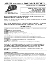
6 in.
(152 mm)
2 / in.
(71 mm)
13
16
3 / in.
(80 mm)
3
16
Air inlet
2 / in.
(73 mm)
7
8
1 / in.
(46 mm)
13
16
4 in.
(101 mm)
11 in.
(279 mm)
/ in.
(19 mm)
3
4
Lubricant
outlet
/ in. NPTF
1
4
/ in.-20
threaded
mounting
holes
(4 places)
1
4
2 / in.
(57 mm)
1
4
27 / in.
(695 mm)
3
8
1 in.
(25,4 mm)
pump
tube
Disassembly
1 Remove valve cap (12) and trip rod
pin (11).
2
Unscrew four nuts (65) from tie rods (66)
and remove trip rod collar (13).
3 Unscrew trip sleeve (8) from trip rod
(31) and lift air valve casting (9) off of air
cylinder (34).
4 Remove packing nut (68) and packing
cap (71) from air valve casting.
5 Remove four valve cover screws (15)
and cover (62).
6 Remove four toggle plate screws (16),
toggle assembly (63) and trip shoe (64).
7 Remove four valve seat screws (61),
springs (60), valve guide plate (59) and
valve slide seat and gasket (58).
8 Unscrew trip rod packing nut (20) from
air valve casting and remove all packing
parts.
9 Unscrew pump tube from outlet body
(33).
10 Remove air cylinder (34) and air passage
tube (35) from outlet body.
11 Extend air motor piston rod (1) out bot-
tom of outlet body. Place wrenches on
air piston bolt (2) and on wrench flats of
piston rod and unscrew piston rod.
Thread piston rod through gland packing
to allow removal of pump tube.
12 Unscrew gland packing nut (21) from
outlet body and remove all gland parts.
13 Remove priming tube (50) from bushing
extension (51).
!
Notice
If complete disassembly is
required, order repair kit and replace all
gaskets, o-rings and packings.
Dimensions
5

14 Extend plunger rod (43) out bushing
extension and unscrew priming plunger
(49) to allow removal of priming check
parts and plunger rod (43).
15 Remove bushing extension (51) and
unscrew plunger and bushing assembly
(40) from pump tube. Unscrew coupling
nut (36) from plunger adapter (53) to
allow removal of plunger and bushing
assembly intact, reducing the chance of
losing ball stop (38) and check ball (39).
Assembly
To assemble, perform Disassembly
procedures in reverse. Tighten fasten ers per
stated torque specifications.
!
Notice
Prevent damage to air piston
packing, pump gland packing, and to
help increase packing life, lubricate air
cylinder and air piston rod before
assembly.
Thread piston rod through gland
packing when assembling pump.
Before tightening four valve seat screws (61),
align valve slide and seat plate (58), slide
valve gasket (56) and air valve casting (9) by
placing a rod through the center hole.
Start all fasteners by hand to avoid strip-
ping threads when reassembling.
Repair
Repair is limited to replacement of listed
service parts. Special procedures and tools
are required. Contact Lincoln customer ser-
vice, One Lincoln Way, St. Louis, MO 63120-
1578, (314) 679-4200 for your nearest
authorized service center.
When ordering replacement parts, list
part number, description, model number
and series letter.
Service parts
1
2
3
4
3
5
6
7
8
9
10
11
12
13
14
15
16
17
18
19
20
Tighten to
10 to 15 ft.lbf
(13 to 20 Nm)
21
22
23
24
25
26
27
28
Use Loctite 510 gasket
eliminator on threads
29
30
31
32
33
7
6
34
35
6

Service parts
A
36
37
29
30
32
Use Loctite 510
gasket eliminator
on threads
38
39
40
Bushing and
plunger
assembly
38
39
41
42
43
44
45
46
47
48
49
50
1 in. (25,4 mm) diameter
51
52
52
53
Pump
tube
Piston
rod
7

Service parts
16
(6 required)
tighten to
30 to 40 in.lbf
(3,3 to 4,5 Nm)
54
55
56
/ in. NPTF
air inlet
1
4
57
58
39
58
59
60
61
16
Lubricate balls and
springs before
assembly
Tighten to
30 to 40 in.lbf
(3,3 to 4,5 Nm)
62
15
Tighten to
90 to 100 in.lbf
(10 to 11,2 Nm)
Air valve
mechanism
14
63
64
Lubricant
outlet
/ in. NPTF
1
4
65
66
67
68
69
70
71
Air exhaust
port
To lubricate air valve
mechanism
1 Disconnect air to pump.
2 Perform pressure relief procedure.
3 Remove four cover screws, cover plate
and cover plate gasket.
4 Remove air valve casting from the pump
and disassemble.
5 Clean or flush the air valve casting to
remove any chips or other foreign
particles.
6 Before replacing toggle assembly, pack
cavity with grease using approximately
1
1
/2 ounces of N.L.G.I. No. 1 (light grade)
water repellent grease.
7 Replace cover plate gasket, cover plate
and cover screws. Tighten to prevent air
leaks.
Optional eyebolt kit
(For hoisting purposes. Parts must be
ordered separately)
73
72
(Thread to
valve cap (12))
!
Notice
Start fasteners by hand to avoid
stripping threads when reassembling.
8 Periodic inspection of parts at least once a
year is advised.
Do not disassemble or assemble pump
with pressure applied to pump or
system.
Relieve all pressure from system be-
fore and after use of pump.
Failure to comply may result in death
or serious injury.
WARNING
8

Service parts list
Item no. Description Part no. Qty. Item no. Description Part no. Qty.
1 Air motor piston rod 11340
1)
1 37 Coupling stud 11346 1
2 Air piston bolt 11329 1 38 Ball stop 57027 2
3 Air piston washer 48212 2 39 Ball 69102
1)3)
1
4 Air piston packing 34090
2)
1 40 Plunger and bushing assembly 90554 1
5 Air piston nut 11337 1 41 Check seat gasket 31047
1)3)
1
6 Air cylinder gasket 33014
1)
2 42 Check seat 11726
1)3)
1
7 0-ring 34368
1)
2 43 Plunger rod 11723
1)3)
1
8 Trip sleeve 11947 1 44 Check stop 11722 1
9 Air valve casting 237563 1 45 Priming check packing 35073
1)3)
10 Valve cap gasket 30011
1)
1 46 Check washer 11702
1)3)
1
11 Trip rod pin 11472
1)
1 47 Priming check 11721
1)3)
1
12 Valve cap 11470 1 48 Priming check seat 11725
1)3)
1
13 Trip rod collar 11471 1 49 Priming plunger 11724
1)3)
1
14 Cover gasket 34158
1)
1 50 Priming tube 239719 1
15 Valve cover screw 236868 4 51 Bushing extension 61273 1
16 Toggle plate screw 236869 6 52 Bushing gasket 31049 2
17 Gasket 33039
1)
1 53 Plunger adapter 11344 1
18 Packing washer 236616
1)2)
1 54 Muffler cover 236615 1
19 Trip rod packing 236835
1)2)
1 55 Muffler 236833 1
20 Trip rod packing nut 245425 1 56 Slide valve gasket 38162
1)
1
21 Gland packing nut 12333 1 57 Spring 56038
1)
2
22 Gland packing washer 48268 1 58 Valve slide and seat 83063 1
23 Gland packing 34180 1 59 Valve guide plate 45605 1
24 Gland gasket 31050
1)
60 Spring 55138 4
25 Gland packing spacer 14940 1 61 Valve seat bolt 236870 4
26 0-ring 34572
1)
1 62 Cover 236286 1
27 U-cup packing 38165
1)
1 63 Toggle plate 91331
2)
1
28 Gland packing washer 48213 1 64 Trip shoe 11475 1
29 Connector gasket 31048
1)
65 Tie rod nut 51009 4
30 Piston rod connector 11349 1 66 Tie rod 10294 4
31 Trip rod 90691
2)
1 67 Packing nut gasket 30003 1
32 Pump tube gasket 31054
1)
1 68 Packing nut 11904 1
33 Outlet body 40537 1 69 Plunger packing washer 48237 1
34 Air cylinder 61041
2)
1 70 Plunger packing 34110 1
35 Air passage tube 61502 1 71 Packing cap 11905 1
36 Coupling nut 11345 1 72 Extension adapter 236975 1
73 Eye bolt 68531 1
1)
Included in 83054 pump repair kit.
2)
Recommended service part
3)
Included in 83001 power pump tube repair kit.
9

EC Declaration of
Conformity in
accordance with
Machinery Directive
2006/42/EC, Annex II
Part 1 A
The manufacturer Lincoln Industrial, One
Lincoln Way, St. Louis, MO 63120-1578
USA hereby declares that the machine
Designation: High-pressure air operated
chassis pump 50:1
Type: 2 1/2 in. (63,5 mm) Model 82050,
series “J”.
Year of construction: see type identifica-
tion plate complies with all basic require-
ments of the following directives at the time
when first being launched in the market.
Machinery directive 2006/42/EC
and RoHS II 2011/65/EU
Applied standards DIN EN ISO
12100:2011-3, DIN EN 809-1:2011,
DIN EN 4414:2011-04.
In the case of modifications or alterations of
the above mentioned machine not author-
ized by the manufacturer validity of this EC
declaration of conformity will cease. The
person empowered to assemble the techni-
cal documentation on behalf of the manu-
facturer is the head of standardization; see
EC-Representative‘s address.
EC-Representative
SKF Lubrication Systems Germany GmbH
Heinrich-Hertz-Str. 2-8
DE - 69190 Walldorf
Manufacturer
Lincoln Industrial, One Lincoln Way
St. Louis, MO 63120-1578 USA
Robert Hoefler,
Director Product Development /
Product Engineering
January 15, 2015
10

Lincoln industrial
standard warranty
Limited warranty
Lincoln warrants the equipment manufac-
tured and supplied by Lincoln to be free
from defects in material and workmanship
for a period of one (1) year following the
date of purchase, excluding there from any
special, extended, or limited warranty pub-
lished by Lincoln. If equipment is deter-
mined to be defective during this warranty
period, it will be repaired or replaced, within
Lincoln’s sole discretion, without charge.
This warranty is conditioned upon the de-
termination of a Lincoln authorized repre-
sentative that the equipment is defective. To
obtain repair or replacement, you must ship
the equipment, transportation charges pre-
paid, with proof of purchase to a Lincoln Au-
thorized Warranty and Service Center within
the warranty period.
This warranty is extended to the original
retail purchaser only. This warranty does
not apply to equipment damaged from ac-
cident, overload, abuse, misuse, negligence,
faulty installation or abrasive or corrosive
material, equipment that has been altered,
or equipment repaired by anyone not au-
thorized by Lincoln. This warranty applies
only to equipment installed, operated and
maintained in strict accordance with the
written specifications and recommendations
provided by Lincoln or its authorized field
personnel.
This warranty is exclusive and is in lieu
of any other warranties, express or im-
plied, including, but not limited to, the
warranty of merchantability or warranty
of fitness for a particular purpose. War-
ranty on items sold by Lincoln, but not
manufactured by Lincoln are subject to
the warranty consideration, if any, of
their manufacturer (such as hoses, hy-
draulic and electric motors, electrical
controllers, etc.) Assistance in making
such warranty claims can be offered as
required.
In no event shall Lincoln be liable for inci-
dental or consequential damages. Lincoln’s
liability for any claim for loss or damages
arising out of the sale, resale or use of any
Lincoln equipment shall in no event exceed
the purchase price. Some jurisdictions do
not allow the exclusion or limitation of inci-
dental or consequential damages, therefore
the above limitation or exclusion may not
apply to you.
This warranty gives you specific legal rights.
You may also have other rights that vary by
jurisdiction.
Customers not located in the Western
Hemisphere or East Asia: Please contact
SKF Lubrication Systems, Germany, GmbH
for your warranty rights.
Lincoln Industrial Special
limited warranties
Special limited 2 year warranty
SL-V series, single injectors – 85772,
85782, replacement injectors – 85771,
85781, and FlowMaster II
Lincoln warrants the SL-V Injector series
and bare FlowMaster II “pump only” models
to be free from defects in material and
workmanship for two (2) years following the
date of purchase. If an injector model (sin-
gle or replacement) or “bare” FlowMaster II
pump is determined to be defective by Lin-
coln, in its sole discretion, during this war-
ranty period, it will be repaired or replaced,
at Lincoln’s discretion, without charge.
Special limited 5 year warranty
series 20, 25, 40 bare pumps, pmv bare
pumps, heavy duty and 94000 series bare
reels
Lincoln warrants series 20, 25, 40 bare
pumps, PMV bare pumps, Heavy Duty
(82206), Mini Bench (81133, 81323), and
all 94000 LFR series (single arm and dual
arm) bare reels to be free from defects in
material and workmanship for five (5) years
following the date of purchase. If equipment
is determined by Lincoln, in its sole discre-
tion, to be defective during the first year of
the warranty period, it will be repaired or re-
placed at Lincoln’s discretion, without
charge. In years two (2) and three (3), the
warranty on this equipment is limited to re-
pair with Lincoln paying parts and labor
only. In years four (4) and five (5), the war-
ranty on this equipment is limited to repair
with Lincoln paying for parts only.
Special limited 5 year warranty
limited oil meters, limited fluid control
valves, aod (air-operated diaphragm
pumps)
Lincoln warrants the 716 series Control
Valves, 916 series Lube Meters, Electronic
Lube Meters (980. 981, 982 series), our
Universal Inline Digital Meters (814/817 se-
ries), and our AOD Pump offering to be free
from defects in material and workmanship
for five (5) years following the date of pur-
chase. If either is determined to be defective
by Lincoln, in its sole discretion, during the
warranty period, they will be repaired or re-
placed, at Lincoln’s discretion, without
charge.
Special DEF (diesel exhaust fluid) limited
warranty
DEF products are warranted to be free from
defects in material and workmanship for a
period of one (1) year following the date of
purchase. The following exceptions to the
standard warranty period are in effect;
• 85700-30/85700-50 DEF hose reels
(bare reel only), 277251/277252 AC DEF
pumps, and 277256 and 277257 DEF
meters are warranted for two (2) years
from date of purchase,
• 85623 DEF AOD (air operated diaphragm)
pumps are covered under the standard
five (5) year AOD pump warranty.
If either is determined to be defective by
Lincoln, in its sole discretion, during the
warranty period, they will be repaired or re-
placed, at Lincoln’s discretion, without
charge.
Lincoln Industrial contact information
To find Lincoln Industrial’s nearest service
center call the following number;
customer service 314-679-4200
(international number 01-314-679-4200)
or you may also use our website
www.lincolnindustrial.com
11

® SKF is a registered trademark of the SKF Group.
® Lincoln is a registered trademark of Lincoln Industrial Corp.
© SKF Group 2015
The contents of this publication are the copyright of the publisher and may not be reproduced (even extracts) unless prior written permis-
sion is granted. Every care has been taken to ensure the accuracy of the information contained in this publication but no liability can be
accepted for any loss or damage whether direct, indirect or consequential arising out of the use of the information contained herein.
SKF PUB LS/I4 15886 EN.R1 · July 2015 · Form 403510S
The Power of Knowledge Engineering
Combining products, people, and application-specific knowledge, SKF
delivers innovative solutions to equipment manufacturers and production
facilities in every major industry worldwide. Having expertise in multiple
competence areas supports SKF Life Cycle Management, a proven approach
to improving equipment reliability, optimizing operational and energy
efficiency and reducing total cost of ownership.
These competence areas include bearings and units, seals, lubrication
systems, mechatronics, and awide range of services, from 3-D computer
modelling to cloud-based condition monitoring and asset management
services.
SKF’s global footprint provides SKF customers with uniform quality standards
and worldwide product availability. Our local presence provides direct access
to the experience, knowledge and ingenuity of SKF people.
SKF BeyondZero
SKF BeyondZero is more than our climate strategy
for a sustainable environment: it is our mantra;
away of thinking, innovating and acting.
For us, SKF BeyondZero means that we will reduce
the negative environmental impact from our own
operations and at the same time, increase the
positive environmental contribution by offering our
customers the SKF BeyondZero portfolio of
products and services with enhanced environmental performance
characteristics.
For inclusion in the SKF BeyondZero portfolio, a product, service or solution
must deliver significant environmental benefits without serious
environmental trade-offs.
lincolnindustrial.com skf.com/lubrication
/