Panasonic CS-E15NKDW User manual

Category
Split-system air conditioners
Type
User manual

This manual is also suitable for

© Panasonic HA Air-Conditioning (M) Sdn. Bhd. 2011.
Unauthorized copying and distribution is a violation of law.
Order No: PHAAM1112080C2
Indoor Unit Outdoor Unit
CS-E7NKDW
CS-E9NKDW
CS-E12NKDW
CS-E15NKDW
CS-E18NKDW
CU-E7NKD
CU-E9NKD
CU-E12NKD
CU-E15NKD
CU-E18NKD
Please file and use this manual together with the service manual for Model No. U-2E18CBPG, Order No. RAC0209005C2, Model No.
U-3E18JBE, U-4E23JBE, Order No. PHAAM1004141C2 and Model No. U-2E15GBE, Order No. MAC0704001A2.
PRECAUTION OF LOW TEMPERATURE
In order to avoid frostbite, be assured of no refrigerant leakage during the installation or repairing of refrigerant circuit.
This service information is designed for experienced repair technicians only and is not designed for use by the general public.
It does not contain warnings or cautions to advise non-technical individuals of potential dangers in attempting to service a product.
Products powered by electricity should be serviced or repaired only by experienced professional technicians. Any attempt to service
or repair the product or products dealt with in this service information by anyone else could result in serious injury or death.
WARNING
2
TABLE OF CONTENTS
1. Safety Precautions .............................................3
2. Specification .......................................................5
3. Features.............................................................19
4. Location of Controls and Components..........20
4.1 Indoor Unit ..................................................20
4.2 Outdoor Unit ...............................................20
4.3 Remote Control ..........................................20
5. Dimensions .......................................................21
5.1 Indoor Unit ..................................................21
5.2 Outdoor Unit ...............................................23
6. Refrigeration Cycle Diagram ...........................24
6.1 CU-E7NKD CU-E9NKD CU-E12NKD
CU-E15NKD ...............................................24
6.2 CU-E18NKD ...............................................25
7. Block Diagram ..................................................26
7.1 CU-E7NKD CU-E9NKD CU-E12NKD
CU-E15NKD ...............................................26
7.2 CU-E18NKD ...............................................27
8. Wiring Connection Diagram ............................28
8.1 Indoor Unit ..................................................28
8.2 Outdoor Unit ...............................................30
9. Electronic Circuit Diagram ..............................32
9.1 Indoor Unit ..................................................32
9.2 Outdoor Unit ...............................................34
10. Printed Circuit Board .......................................36
10.1 Indoor Unit ..................................................36
10.2 Outdoor Unit ...............................................39
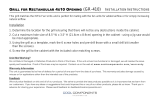
11. Installation Instruction.....................................41
11.1 Select the Best Location.............................41
11.2 Indoor Unit ..................................................42
11.3 Outdoor Unit ...............................................46
12. Operation and Control .....................................49
12.1 Basic Function ............................................49
12.2 Indoor Fan Motor Operation .......................50
12.3 Outdoor Fan Motor Operation ....................51
12.4 Airflow Direction..........................................51
12.5 Quiet operation (Cooling Mode/Cooling area
of Dry Mode)...............................................52
12.6 Quiet operation (Heating) ...........................53
12.7 Powerful Mode Operation...........................53
12.8 Timer Control..............................................53
12.9 Auto Restart Control...................................54
12.10 Indication Panel..........................................54
12.11 nanoe-G Operation.....................................55
12.12 Mild Dry Cooling Operation ........................57
12.13 ECONAVI and AUTO COMFORT
Operation....................................................58
13. Operation Control (For Multi Split
Connection).......................................................62
13.1 Cooling operation .......................................62
13.2 Soft Dry Operation..................................... 62
13.3 Heating Operation ..................................... 62
13.4 Automatic Operation.................................. 63
13.5 Indoor Fan Motor Operation ...................... 63
13.6 Powerful Mode Operation.......................... 63
13.7 Auto restart control .................................... 63
13.8 Indication Panel ......................................... 63
13.9 Mild Dry Cooling Operation ....................... 63
14. Protection Control........................................... 64
14.1 Protection Control For All Operations........ 64
14.2 Protection Control For Cooling & Soft Dry
Operation................................................... 66
14.3 Protection Control For Heating
Operation................................................... 67
15. Servicing Mode ................................................ 68
15.1 Auto OFF/ON Button ................................. 68
15.2 Remote Control Button.............................. 69
16. Troubleshooting Guide................................... 70
16.1 Refrigeration Cycle System....................... 70
16.2 Breakdown Self Diagnosis Function.......... 72
16.3 Error Code Table ....................................... 73
16.4 Self-diagnosis Method............................... 75
17. Disassembly and Assembly Instructions ... 104
17.1 CS-E7NK CS-E9NK CS-E12NK
CS-E15NK ............................................... 104
17.2 CS-E18NK ............................................... 108
17.3 Outdoor Electronic Controller Removal
Procedure ................................................ 112
18. Technical Data ............................................... 114
18.1 Operation Characteristics........................ 114
18.2 Sensible Capacity Chart.......................... 134
19. Exploded View and Replacement Parts
List .................................................................. 136
19.1 Indoor Unit ............................................... 136
19.2 Outdoor Unit ............................................ 142
3
CAUTION
WARNING
WARNING
1. Safety Precautions
Read the following “SAFETY PRECAUTIONS” carefully before perform any servicing.
Electrical work must be installed or serviced by a licensed electrician. Be sure to use the correct rating of the
power plug and main circuit for the model installed.
The caution items stated here must be followed because these important contents are related to safety. The
meaning of each indication used is as below. Incorrect installation or servicing due to ignoring of the instruction
will cause harm or damage, and the seriousness is classified by the following indications.
This indication shows the possibility of causing death or serious injury.
This indication shows the possibility of causing injury or damage to properties.
The items to be followed are classified by the symbols:
Carry out test run to confirm that no abnormality occurs after the servicing. Then, explain to user the operation,
care and maintenance as stated in instructions. Please remind the customer to keep the operating instructions for
future reference.
1. Do not modify the machine, part, material during repairing service.
2. If wiring unit is supplied as repairing part, do not repair or connect the wire even only partial wire break. Exchange the whole wiring unit.
3. Do not wrench the fasten terminal. Pull it out or insert it straightly.
4. Engage authorized dealer or specialist for installation and servicing. If installation or servicing done by the user is defective, it will cause
water leakage, electrical shock or fire.
5. Install according to this installation instructions strictly. If installation is defective, it will cause water leakage, electric shock or fire.
6. Use the attached accessories parts and specified parts for installation and servicing. Otherwise, it will cause the set to fall, water leakage,
fire or electrical shock.
7. Install at a strong and firm location which is able to withstand the set’s weight. If the strength is not enough or installation is not properly done,
the set will drop and cause injury.
8. For electrical work, follow the local national wiring standard, regulation and the installation instruction. An independent circuit and single
outlet must be used. If electrical circuit capacity is not enough or defect found in electrical work, it will cause electrical shock or fire.
9. This equipment is strongly recommended to install with Earth Leakage Circuit Breaker (ELCB) or Residual Current Device (RCD).
Otherwise, it may cause electrical shock and fire in case equipment breakdown or insulation breakdown.
10. Do not use joint cable for indoor/outdoor connection cable. Use the specified indoor/outdoor connection cable, refer to installation instruction
CONNECT THE CABLE TO THE INDOOR UNIT and connect tightly for indoor/outdoor connection. Clamp the cable so that no external force
will be acted on the terminal. If connection or fixing is not perfect, it will cause heat up or fire at the connection.
11. Wire routing must be properly arranged so that control board cover is fixed properly. If control board cover is not fixed perfectly, it will cause
heat-up or fire at the connection point of terminal, fire or electrical shock.
12. When install or relocate air conditioner, do not let any substance other than the specified refrigerant, eg. air etc. mix into refrigeration
cycle (piping). (Mixing of air etc. will cause abnormal high pressure in refrigeration cycle and result in explosion, injury etc.).
13. Do not install outdoor unit near handrail of veranda. When installing air-conditioner unit at veranda of high rise building, child may climb up to
outdoor unit and cross over the handrail and causing accident.
14. This equipment must be properly earthed. Earth line must not be connected to gas pipe, water pipe, earth of lightning rod and
telephone. Otherwise, it may cause electric shock in case equipment breakdown or insulation breakdown.
15. Keep away from small children, the thin film may cling to nose and mouth and prevent breathing.
16. Do not use unspecified cord, modified cord, joint cord or extension cord for power supply cord. Do not share the single outlet with
other electrical appliances. Poor contact, poor insulation or over current will cause electrical shock or fire.
17. Tighten the flare nut with torque wrench according to specified method. If the flare nut is over-tightened, after a long period, the flare
may break and cause refrigerant gas leakage.
18. For R410A models, when connecting the piping, do not use any existing (R22) pipes and flare nuts. Using such same may cause
abnormally high pressure in the refrigeration cycle (piping), and possibly result in explosion and injury. Use only R410A materials.
Thickness of copper pipes used with R410A must be more than 0.8mm. Never use copper pipes thinner than 0.8mm.
It is desirable that the amount of residual oil is less than 40 mg/10m.
This symbol denotes item that is PROHIBITED from doing.
4
CAUTION
WARNING
19. During installation, install the refrigerant piping properly before run the compressor. (Operation of compressor without fixing refrigeration piping
and valves at opened condition will cause suck-in of air, abnormal high pressure in refrigeration cycle and result in explosion, injury etc).
20. During pump down operation, stop the compressor before remove the refrigeration piping. (Removal of refrigeration piping while compressor is
operating and valves are opened condition will cause suck-in of air, abnormal high pressure in refrigeration cycle and result in explosion,
injury etc.)
21. After completion of installation or service, confirm there is no leakage or refrigerant gas. It may generate toxic gas when the refrigerant
contacts with fire.
22. Ventilate if there is refrigerant gas leakage during operation. It may cause toxic gas when the refrigerant contacts with fire.
23. Do not insert your fingers or other objects into the unit, high speed rotating fan may cause injury.
24. Must not use other parts except original parts describe in catalog and manual.
25. Using of refrigerant other than the specified type may cause product damage, burst and injury etc.
1. Do not install the unit at place where leakage of flammable gas may occur. In case gas leaks and accumulates at surrounding of the
unit, it may cause fire.
2. Carry out drainage piping as mentioned in installation instructions. If drainage is not perfect, water may enter the room and damage
the furniture.
3. Tighten the flare nut with torque wrench according to specified method. If the flare nut is over-tightened, after a long period, the flare
may break and cause refrigerant gas leakage.
4. Do not touch outdoor unit air inlet and aluminium fin. It may cause injury.
5. Select an installation location which is easy for maintenance.
6. Pb free solder has a higher melting point than standard solder; typically the melting point is 50°F – 70°F (30°C – 40°C) higher. Please use
a high temperature solder iron. In case of the soldering iron with temperature control, please set it to 700 ± 20°F (370 ± 10°C).
Pb free solder will tend to splash when heated too high (about 1100°F / 600°C).
7. Power supply connection to the air conditioner. Connect the power supply cord of the air conditioner to the mains using one of the following
methods.
Power supply point shall be the place where there is ease for access for the power disconnection in case of emergency. In some countries,
permanent connection of this room air conditioner to the power supply is prohibited.
i. Power supply connection to the receptacle using a power plug. Use an approved 15/16A (3/4~1.75HP), 16A (2.0HP), 20A (2.5HP) or
25A (3.0HP) power plug with earth pin for the connection to the socket.
ii. Power supply connection to a circuit breaker for the permanent connection. Use an approved 16A (3/4~2.0HP), 20A (2.5HP) or
25A (3.0HP) circuit breaker for the permanent connection. It must be a double pole switch with a minimum 3.0 mm contact gap.
8. Do not release refrigerant during piping work for installation, servicing, reinstallation and during repairing a refrigerant parts.
Take care of the liquid refrigerant, it may cause frostbite.
9. Installation or servicing work: It may need two people to carry out the installation or servicing work.
10. Do not install this appliance in a laundry room or other location where water may drip from the ceiling, etc.
11. Do not sit or step on the unit, you may fall down accidentally.
12. Do not touch the sharp aluminium fins or edges of metal parts.
If you are required to handle sharp parts during installation or servicing, please wear hand glove.
Sharp parts may cause injury.
5
2. Specification
Indoor CS-E7NKDW CS-E9NKDW
Model
Outdoor CU-E7NKD CU-E9NKD
Performance Test Condition JIS JIS
Phase, Hz Single, 50 Single, 50
Power Supply
V 220 230 220 230
Min. Mid. Max. Min. Mid. Max. Min. Mid. Max. Min. Mid. Max.
kW 0.75 2.05 2.40 0.75 2.05 2.40 0.85 2.50 3.00 0.85 2.50 3.00
BTU/h 2560 6990 8180 2560 6990 8180 2900 8530 10200 2900 8530 10200
Capacity
Kcal/h 650 1760 2060 650 1760 2060 730 2150 2580 730 2150 2580
Running Current A - 2.3 - - 2.2 - - 2.7 - - 2.6 -
Input Power W 240 470 580 240 470 580 245 545 740 245 545 740
Annual Consumption kWh - 235 - - 235 - - 273 - - 273 -
W/W 3.13 4.36 4.14 3.13 4.36 4.14 3.47 4.59 4.05 3.47 4.59 4.05
BTU/hW 10.67 14.87 14.10 10.67 14.87 14.10 11.84 15.65 13.78 11.84 15.65 13.78
EER
Kcal/hW 2.71 3.74 3.55 2.71 3.74 3.55 2.98 3.94 3.49 2.98 3.94 3.49
Power Factor % - 93 - - 93 - - 92 - - 91 -
dB-A 37 / 24 / 21 37 / 24 / 21 39 / 25 / 21 39 / 25 / 21
Indoor Noise (H / L / QLo)
Power Level dB 53 / - 53 / - 55 / - 55 / -
dB-A 45 / - 45 / - 46 / - 46 / -
Cooling
Outdoor Noise (H / L)
Power Level dB 60 / - 60 / - 61 / - 61 / -
kW 0.75 2.80 4.00 0.75 2.80 4.00 0.85 3.40 5.00 0.85 3.40 5.00
BTU/h 2560 9550 13600 2560 9550 13600 2900 11600 17100 2900 11600 17100
Capacity
Kcal/h 650 2410 3440 650 2410 3440 730 2920 4300 730 2920 4300
Running Current A - 3.1 - - 3.0 - - 3.6 - - 3.4 -
Input Power W 230 635 1.02k 230 635 1.02k 240 740 1.31k 240 740 1.31k
W/W 3.26 4.41 3.92 3.26 4.41 3.92 3.54 4.59 3.82 3.54 4.59 3.82
BTU/hW 11.13 15.04 13.33 11.13 15.04 13.33 12.08 15.68 13.05 12.08 15.68 13.05
COP
Kcal/hW 2.83 3.80 3.37 2.83 3.80 3.37 3.04 3.95 3.28 3.04 3.95 3.28
Power Factor % - 93 - - 92 - - 93 - - 95 -
dB-A 38 / 25 / 22 38 / 25 / 22 40 / 27 / 24 40 / 27 / 24
Indoor Noise (H / L / QLo)
Power Level dB 54 / - 54 / - 56 / - 56 / -
dB-A 46 / - 46 / - 47 / - 47 / -
Heating
Outdoor Noise (H / L)
Power Level dB 61 / - 61 / - 62 / - 62 / -
Low Temp. : Capacity (kW) / I.Power (W) / COP 2.90 / 900 / 3.22 3.62 / 1.16k / 3.12
Extr Low Temp. : Capacity (kW) / I.Power (W) / COP 2.35 / 930 / 2.53 2.88 / 1.19k / 2.42
Max Current (A) / Max Input Power (W) 4.7 / 1.02k 5.8 / 1.31k
Starting Current (A) 3.1 3.6
Type Hermetic Motor / Rotary Hermetic Motor / Rotary
Motor Type Brushless (6 poles) Brushless (6 poles)
Compressor
Output Power W 650 700
6
Type Cross-flow Fan Cross-flow Fan
Material ASG20K1 ASG20K1
Motor Type Transistor (8-poles) Transistor (8-poles)
Input Power W 94.8 94.8
Output Power W 40 40
Cool rpm 590 630
QLo
Heat rpm 680 670
Cool rpm 670 730
Lo
Heat rpm 730 820
Cool rpm 860 950
Me
Heat rpm 910 1030
Cool rpm 1050 1180
Hi
Heat rpm 1090 1240
Cool rpm 1110 1240
Indoor Fan
Speed
SHi
Heat rpm 1150 1280
Type Propeller Fan Propeller Fan
Material PP PP
Motor Type Induction (6-poles) Induction (6-poles)
Input Power W - -
Output Power W 25 25
Outdoor Fan
Speed Hi rpm 730 750 750 770
Moisture Removal L/h (Pt/h) 1.3 (2.7) 1.5 (3.2)
Cool m
3
/min (ft
3
/min) 5.6 (198) 4.9 (173)
QLo
Heat m
3
/min (ft
3
/min) 6.0 (212) 5.3 (187)
Cool m
3
/min (ft
3
/min) 6.5 (230) 6.0 (212)
Lo
Heat m
3
/min (ft
3
/min) 7.2 (254) 7.1 (251)
Cool m
3
/min (ft
3
/min) 8.7 (307) 8.7 (307)
Me
Heat m
3
/min (ft
3
/min) 9.3 (328) 9.6 (339)
Cool m
3
/min (ft
3
/min) 10.9 (385) 11.3 (400)
Hi
Heat m
3
/min (ft
3
/min) 11.4 (400) 11.9 (420)
Cool m
3
/min (ft
3
/min) 11.6 (410) 11.7 (410)
Indoor
Airflow
SHi
Heat m
3
/min (ft
3
/min) 12.0 (424) 12.1 (427)
Cool m
3
/min (ft
3
/min) 32.4 (1145) - 33.9 (1195) 29.4 (1040) - 29.8 (1050)
Outdoor
Airflow
Hi
Heat m
3
/min (ft
3
/min) 32.4 (1145) - 33.9 (1195) 29.4 (1040) - 29.8 (1050)
Control Device Check Valve & Capillary Tube Check Valve & Capillary Tube
Refrigerant Oil cm
3
FV50S (320) FV50S (320)
Refrigeration
Cycle
Refrigerant Type g (oz) R410A, 830 (29.3) R410A, 960 (33.9)
Height (I/D / O/D) mm (inch) 290 (11-7/16) / 542 (21-11/32) 290 (11-7/16) / 542 (21-11/32)
Width (I/D / O/D) mm (inch) 870 (34-9/32) / 780 (30-23/32) 870 (34-9/32) / 780 (30-23/32)
Dimension
Depth (I/D / O/D) mm (inch) 214 (8-7/16) / 289 (11-13/32) 214 (8-7/16) / 289 (11-13/32)
Weight Net (I/D / O/D) kg (lb) 9 (20) / 31 (68) 9 (20) / 33 (73)
Pipe Diameter (Liquid / Gas) mm (inch) 6.35 (1/4) / 9.52 (3/8) 6.35 (1/4) / 9.52 (3/8)
Standard Length m (ft) 5 (16.4) 5 (16.4)
Length Range (min – max) m (ft) 3 (9.8) ~ 15 (49.2) 3 (9.8) ~ 15 (49.2)
I/D & O/D Height Different m (ft) 15.0 (49.2) 15.0 (49.2)
Additional Gas Amount g/m (oz/ft) 20 (0.2) 20 (0.2)
Piping
Length for Additional Gas m (ft) 7.5 (24.6) 7.5 (24.6)
7
Inner Diameter mm 16 16
Drain Hose
Length mm 650 650
Fin Material Aluminium (Pre Coat) Aluminium (Pre Coat)
Fin Type Slit Fin Slit Fin
Row x Stage x FPI 2 x 15 x 17 2 x 15 x 21
Indoor Heat
Exchanger
Size (W x H x L) mm 610 x 315 x 25.4 610 x 315 x 25.4
Fin Material Aluminium (Blue Coat) Aluminium (Blue Coat)
Fin Type Corrugated Fin Corrugated Fin
Row x Stage x FPI 1 x 20 x 19 2 x 24 x 17
Outdoor
Heat
Exchanger
Size (W x H x L) mm 22 x 508 x 708 36.4 x 504 x 713:684
Material Polypropelene Polypropelene
Air Filter
Type One-touch One-touch
Power Supply Outdoor Power Supply Outdoor Power Supply
Power Supply Cord A Nil Nil
Thermostat Electronic Contol Electronic Contol
Protection Device Electronic Contol Electronic Contol
Dry Bulb Wet Bulb Dry Bulb Wet Bulb
Maximum 32 23 32 23
Cooling
Minimum 16 11 16 11
Maximum 30 - 30 -
Indoor
Operation
Range
Heating
Minimum 16 - 16 -
Maximum 43 26 43 26
Cooling
Minimum 16 11 16 11
Maximum 24 18 24 18
Outdoor
Operation
Range
Heating
Minimum -5 -6 -5 -6
1. Cooling capacities are based on indoor temperature of 27°C Dry Bulb (80.6°F Dry Bulb), 19.0°C Wet Bulb (66.2°F Wet Bulb) and outdoor air
temperature of 35°C Dry Bulb (95°F Dry Bulb), 24°C Wet Bulb (75.2°F Wet Bulb)
2. Heating capacities are based on indoor temperature of 20°C Dry Bulb (68°F Dry Bulb) and outdoor air temperature of 7°C Dry Bulb
(44.6°F Dry Bulb), 6°C Wet Bulb (42.8°F Wet Bulb)
3. Heating low temperature capacity, Input Power and COP measured at 230 V, indoor temperature 20°C, outdoor 2/1°C
4. Heating extreme low temperature capacity, Input Power and COP measured at 230 V, indoor temperature 20°C, outdoor -7/-8°C
5. Specifications are subjected to change without prior notice for further improvement.
8
Indoor CS-E12NKDW CS-E15NKDW
Model
Outdoor CU-E12NKD CU-E15NKD
Performance Test Condition JIS JIS
Phase, Hz Single, 50 Single, 50
Power Supply
V 220 230 220 230
Min. Mid. Max. Min. Mid. Max. Min. Mid. Max. Min. Mid. Max.
kW 0.85 3.50 4.00 0.85 3.50 4.00 0.85 4.20 5.00 0.85 4.20 5.00
BTU/h 2900 11900 13600 2900 11900 13600 2900 14300 17100 2900 14300 17100
Capacity
Kcal/h 730 3010 3440 730 3010 3440 730 3610 4300 730 3610 4300
Running Current A - 4.3 - - 4.1 - - 5.9 - - 5.7 -
Input Power W 250 905 1.18k 250 905 1.18k 260 1.26k 1.57k 260 1.26k 1.57k
Annual Consumption kWh - 453 - - 453 - - 630 - - 630 -
W/W 3.40 3.87 3.39 3.40 3.87 3.39 3.27 3.33 3.18 3.27 3.33 3.18
BTU/hW 11.60 13.15 11.53 11.60 13.15 11.53 11.15 11.35 10.89 11.15 11.35 10.89
EER
Kcal/hW 2.92 3.33 2.92 2.92 3.33 2.92 2.81 2.87 2.74 2.81 2.87 2.74
Power Factor % - 96 - - 96 - - 97 - - 96 -
dB-A 42 / 28 / 21 42 / 28 / 21 43 / 31 / 25 43 / 31 / 25
Indoor Noise (H / L / QLo)
Power Level dB 58 / - 58 / - 59 / - 59 / -
dB-A 48 / - 48 / - 49 / - 49 / -
Cooling
Outdoor Noise (H / L)
Power Level dB 63 / - 63 / - 64 / - 64 / -
kW 0.85 4.40 6.70 0.85 4.40 6.70 0.85 5.30 6.80 0.85 5.30 6.80
BTU/h 2900 15000 22800 2900 15000 22800 2900 18100 23200 2900 18100 23200
Capacity
Kcal/h 730 3780 5760 730 3780 5760 730 4560 5850 730 4560 5850
Running Current A - 5.3 - - 5.1 - - 6.8 - - 6.6 -
Input Power W 245 1.09k 1.93k 245 1.09k 1.93k 255 1.44k 1.94k 255 1.44k 1.94k
W/W 3.47 4.04 3.47 3.47 4.04 3.47 3.33 3.68 3.51 3.33 3.68 3.51
BTU/hW 11.84 13.76 11.81 11.84 13.76 11.81 11.37 12.57 11.96 11.37 12.57 11.96
COP
Kcal/hW 2.98 3.47 2.98 2.98 3.47 2.98 2.86 3.17 3.02 2.86 3.17 3.02
Power Factor % - 93 - - 93 - - 96 - - 95 -
dB-A 42 / 33 / 30 42 / 33 / 30 43 / 35 / 32 43 / 35 / 32
Indoor Noise (H / L / QLo)
Power Level dB 58 / - 58 / - 59 / - 59 / -
dB-A 50 / - 50 / - 51 / - 51 / -
Heating
Outdoor Noise (H / L)
Power Level dB 65 / - 65 / - 66 / - 66 / -
Low Temp. : Capacity (kW) / I.Power (W) / COP 4.85 / 1.67k / 2.90 4.92 / 1.72k / 2.86
Extr Low Temp. : Capacity (kW) / I.Power (W) / COP 3.75 / 1.68k / 2.23 3.94 / 1.83k / 2.15
Max Current (A) / Max Input Power (W) 8.9 / 1.93k 9.0 / 1.94k
Starting Current (A) 5.3 6.8
Type Hermetic Motor / Rotary Hermetic Motor / Rotary
Motor Type Brushless (6 poles) Brushless (6 poles)
Compressor
Output Power W 700 700
9
Type Cross-flow Fan Cross-flow Fan
Material ASG20K1 ASG20K1
Motor Type Transistor (8-poles) Transistor (8-poles)
Input Power W 94.8 94.8
Output Power W 40 40
Cool rpm 630 730
QLo
Heat rpm 950 1000
Cool rpm 830 870
Lo
Heat rpm 1010 1080
Cool rpm 1040 1070
Me
Heat rpm 1150 1210
Cool rpm 1260 1270
Hi
Heat rpm 1300 1350
Cool rpm 1320 1340
Indoor Fan
Speed
SHi
Heat rpm 1340 1370
Type Propeller Fan Propeller Fan
Material PP PP
Motor Type Induction (6-poles) Induction (6-poles)
Input Power W - -
Output Power W 30 30
Outdoor Fan
Speed Hi rpm 810 830 830 850
Moisture Removal L/h (Pt/h) 2.0 (4.2) 2.4 (5.1)
Cool m
3
/min (ft
3
/min) 4.9 (173) 6.0 (212)
QLo
Heat m
3
/min (ft
3
/min) 8.7 (307) 9.2 (325)
Cool m
3
/min (ft
3
/min) 7.2 (254) 7.7 (272)
Lo
Heat m
3
/min (ft
3
/min) 9.4 (332) 10.2 (360)
Cool m
3
/min (ft
3
/min) 9.7 (343) 10.1 (357)
Me
Heat m
3
/min (ft
3
/min) 11.0 (389) 11.7 (413)
Cool m
3
/min (ft
3
/min) 12.5 (440) 12.5 (440)
Hi
Heat m
3
/min (ft
3
/min) 12.8 (450) 13.4 (475)
Cool m
3
/min (ft
3
/min) 13.1 (463) 13.3 (470)
Indoor
Airflow
SHi
Heat m
3
/min (ft
3
/min) 13.3 (470) 13.6 (480)
Cool m
3
/min (ft
3
/min) 30.6 (1080) - 31.0 (1095) 31.0 (1095) - 31.4 (1110)
Outdoor
Airflow
Hi
Heat m
3
/min (ft
3
/min) 30.6 (1080) - 31.0 (1095) 31.0 (1095) - 31.4 (1110)
Control Device Check Valve & Capillary Tube Check Valve & Capillary Tube
Refrigerant Oil cm
3
FV50S (320) FV50S (320)
Refrigeration
Cycle
Refrigerant Type g (oz) R410A, 970 (34.2) R410A, 1.01k (35.7)
Height (I/D / O/D) mm (inch) 290 (11-7/16) / 542 (21-11/32) 290 (11-7/16) / 542 (21-11/32)
Width (I/D / O/D) mm (inch) 870 (34-9/32) / 780 (30-23/32) 870 (34-9/32) / 780 (30-23/32)
Dimension
Depth (I/D / O/D) mm (inch) 214 (8-7/16) / 289 (11-13/32) 214 (8-7/16) / 289 (11-13/32)
Weight Net (I/D / O/D) kg (lb) 9 (20) / 35 (77) 9 (20) / 33 (73)
Pipe Diameter (Liquid / Gas) mm (inch) 6.35 (1/4) / 9.52 (3/8) 6.35 (1/4) / 12.70 (1/2)
Standard Length m (ft) 5 (16.4) 5 (16.4)
Length Range (min – max) m (ft) 3 (9.8) ~ 15 (49.2) 3 (9.8) ~ 15 (49.2)
I/D & O/D Height Different m (ft) 15.0 (49.2) 15.0 (49.2)
Additional Gas Amount g/m (oz/ft) 20 (0.2) 20 (0.2)
Piping
Length for Additional Gas m (ft) 7.5 (24.6) 7.5 (24.6)
10
Inner Diameter mm 16 16
Drain Hose
Length mm 650 650
Fin Material Aluminium (Pre Coat) Aluminium (Pre Coat)
Fin Type Slit Fin Slit Fin
Row x Stage x FPI 2 x 15 x 21 2 x 15 x 21
Indoor Heat
Exchanger
Size (W x H x L) mm 610 x 315 x 25.4 610 x 315 x 25.4
Fin Material Aluminium (Blue Coat) Aluminium (Blue Coat)
Fin Type Corrugated Fin Corrugated Fin
Row x Stage x FPI 2 x 24 x 17 2 x 24 x 17
Outdoor
Heat
Exchanger
Size (W x H x L) mm 36.4 x 504 x 713:684 36.4 x 504 x 713:684
Material Polypropelene Polypropelene
Air Filter
Type One-touch One-touch
Power Supply Outdoor Power Supply Outdoor Power Supply
Power Supply Cord A Nil Nil
Thermostat Electronic Contol Electronic Contol
Protection Device Electronic Contol Electronic Contol
Dry Bulb Wet Bulb Dry Bulb Wet Bulb
Maximum 32 23 32 23
Cooling
Minimum 16 11 16 11
Maximum 30 - 30 -
Indoor
Operation
Range
Heating
Minimum 16 - 16 -
Maximum 43 26 43 26
Cooling
Minimum 16 11 16 11
Maximum 24 18 24 18
Outdoor
Operation
Range
Heating
Minimum -5 -6 -5 -6
1. Cooling capacities are based on indoor temperature of 27°C Dry Bulb (80.6°F Dry Bulb), 19.0°C Wet Bulb (66.2°F Wet Bulb) and outdoor air
temperature of 35°C Dry Bulb (95°F Dry Bulb), 24°C Wet Bulb (75.2°F Wet Bulb)
2. Heating capacities are based on indoor temperature of 20°C Dry Bulb (68°F Dry Bulb) and outdoor air temperature of 7°C Dry Bulb
(44.6°F Dry Bulb), 6°C Wet Bulb (42.8°F Wet Bulb)
3. Heating low temperature capacity, Input Power and COP measured at 230 V, indoor temperature 20°C, outdoor 2/1°C
4. Heating extreme low temperature capacity, Input Power and COP measured at 230 V, indoor temperature 20°C, outdoor -7/-8°C
5. Specifications are subjected to change without prior notice for further improvement.
11
Indoor CS-E18NKDW
Model
Outdoor CU-E18NKD
Performance Test Condition JIS
Phase, Hz Single, 50
Power Supply
V 220 230
Min. Mid. Max. Min. Mid. Max.
kW 0.98 5.00 6.00 0.98 5.00 6.00
BTU/h 3340 17100 20500 3340 17100 20500
Capacity
Kcal/h 840 4300 5160 840 4300 5160
Running Current A - 6.9 - - 6.6 -
Input Power W 280 1.47k 2.03k 280 1.47k 2.03k
Annual Consumption kWh - 735 - - 735 -
W/W 3.50 3.40 2.96 3.50 3.40 2.96
BTU/hW 11.93 11.63 10.10 11.93 11.63 10.10
EER
Kcal/hW 3.00 2.93 2.54 3.00 2.93 2.54
Power Factor % - 97 - - 97 -
dB-A 44 / 37 / 34 44 / 37 / 34
Indoor Noise (H / L / QLo)
Power Level dB 60 / - 60 / -
dB-A 47 / - 47 / -
Cooling
Outdoor Noise (H / L)
Power Level dB 61 / - 61 / -
kW 0.98 5.80 8.00 0.98 5.80 8.00
BTU/h 3340 19800 27300 3340 19800 27300
Capacity
Kcal/h 840 4990 6880 840 4990 6880
Running Current A - 7.2 - - 6.9 -
Input Power W 340 1.54k 2.60k 340 1.54k 2.60k
W/W 2.88 3.77 3.08 2.88 3.77 3.08
BTU/hW 9.82 12.86 10.50 9.82 12.86 10.50
COP
Kcal/hW 2.47 3.24 2.65 2.47 3.24 2.65
Power Factor % - 97 - - 97 -
dB-A 44 / 37 / 34 44 / 37 / 34
Indoor Noise (H / L / QLo)
Power Level dB 60 / - 60 / -
dB-A 47 / - 47 / -
Heating
Outdoor Noise (H / L )
Power Level dB 61 / - 61 / -
Low Temp. : Capacity (kW) / I.Power (W) / COP 5.80 / 2.35k / 2.47
Extr Low Temp. : Capacity (kW) / I.Power (W) / COP 4.98 / 2.41k / 2.07
Max Current (A) / Max Input Power (W) 11.4 / 2.60k
Starting Current (A) 7.2
Type Hermetic Motor / Rotary
Motor Type Brushless (4 poles)
Compressor
Output Power W 900
12
Type Cross-flow Fan
Material ASG30K1
Motor Type Transistor (8-poles)
Input Power W 94.8
Output Power W 40
Cool rpm 960
QLo
Heat rpm 1040
Cool rpm 1040
Lo
Heat rpm 1120
Cool rpm 1160
Me
Heat rpm 1240
Cool rpm 1280
Hi
Heat rpm 1360
Cool rpm 1390
Indoor Fan
Speed
SHi
Heat rpm 1430
Type Propeller Fan
Material PP
Motor Type Induction (6-poles)
Input Power W -
Output Power W 40
Cool rpm 660
Outdoor Fan
Speed Hi
Heat rpm 640
Moisture Removal L/h (Pt/h) 2.8 (5.9)
Cool m
3
/min (ft
3
/min) 12.0 (424)
QLo
Heat m
3
/min (ft
3
/min) 13.2 (466)
Cool m
3
/min (ft
3
/min) 13.2 (466)
Lo
Heat m
3
/min (ft
3
/min) 14.3 (505)
Cool m
3
/min (ft
3
/min) 14.9 (526)
Me
Heat m
3
/min (ft
3
/min) 16.0 (565)
Cool m
3
/min (ft
3
/min) 16.3 (575)
Hi
Heat m
3
/min (ft
3
/min) 17.9 (630)
Cool m
3
/min (ft
3
/min) 18.1 (639)
Indoor
Airflow
SHi
Heat m
3
/min (ft
3
/min) 18.5 (653)
Cool m
3
/min (ft
3
/min) 39.2 (1385)
Outdoor
Airflow
Hi
Heat m
3
/min (ft
3
/min) 37.9 (1340)
Control Device Expansion Valve
Refrigerant Oil cm
3
FV50S (450)
Refrigeration
Cycle
Refrigerant Type g (oz) R410A, 1.22k (43.1)
Height (I/D / O/D) mm (inch) 290 (11-7/16) / 695 (27-3/8)
Width (I/D / O/D) mm (inch) 1070 (42-5/32) / 875 (34-15/32)
Dimension
Depth (I/D / O/D) mm (inch) 240 (9-15/32) / 320 (12-5/8)
Weight Net (I/D / O/D) kg (lb) 11 (24) / 46 (101)
Pipe Diameter (Liquid / Gas) mm (inch) 6.35 (1/4) / 12.70 (1/2)
Standard Length m (ft) 5 (16.4)
Length Range (min – max) m (ft) 3 (9.8) ~ 20 (65.5)
I/D & O/D Height Different m (ft) 15.0 (49.2)
Additional Gas Amount g/m (oz/ft) 20 (0.2)
Piping
Length for Additional Gas m (ft) 7.5 (24.6)
13
Inner Diameter mm 16
Drain Hose
Length mm 650
Fin Material Aluminium (Pre Coat)
Fin Type Slit Fin
Row x Stage x FPI 2 x 15 x 17
Indoor Heat
Exchanger
Size (W x H x L) mm 810 x 315 x 25.4
Fin Material Aluminium (Blue Coat)
Fin Type Corrugated Fin
Row x Stage x FPI 2 x 31 x 19
Outdoor
Heat
Exchanger
Size (W x H x L) mm 36.4 x 651 x 854.5:824.5
Material Polypropelene
Air Filter
Type One-touch
Power Supply Outdoor Power Supply
Power Supply Cord A Nil
Thermostat Electronic Contol
Protection Device Electronic Contol
Dry Bulb Wet Bulb
Maximum 32 23
Cooling
Minimum 16 11
Maximum 30 -
Indoor
Operation
Range
Heating
Minimum 16 -
Maximum 43 26
Cooling
Minimum 16 11
Maximum 24 18
Outdoor
Operation
Range
Heating
Minimum -5 -6
1. Cooling capacities are based on indoor temperature of 27°C Dry Bulb (80.6°F Dry Bulb), 19.0°C Wet Bulb (66.2°F Wet Bulb) and outdoor air
temperature of 35°C Dry Bulb (95°F Dry Bulb), 24°C Wet Bulb (75.2°F Wet Bulb)
2. Heating capacities are based on indoor temperature of 20°C Dry Bulb (68°F Dry Bulb) and outdoor air temperature of 7°C Dry Bulb
(44.6°F Dry Bulb), 6°C Wet Bulb (42.8°F Wet Bulb)
3. Heating low temperature capacity, Input Power and COP measured at 230 V, indoor temperature 20°C, outdoor 2/1°C
4. Heating extreme low temperature capacity, Input Power and COP measured at 230 V, indoor temperature 20°C, outdoor -7/-8°C
5. Specifications are subjected to change without prior notice for further improvement.
14
Multi Split Combination Possibility:
o A single outdoor unit enables air conditioning of up to two separate rooms for U-2E15GBE, U-2E18CBPG.
15
Outdoor Unit : U-2E15GBE
Outdoor Unit : U-2E18CBPG
16
Outdoor Unit : U-3E18JBE
17
Outdoor Unit : U-4E23JBE
18
19
3. Features
Inverter Technology
o Wider output power range
o Energy saving
o Quick Cooling
o Quick Heating
o More precise temperature control
Air Purifying System with nanoe-G
o Deactivates and removes bacterial, viruses and mould
Environment Protection
o Non-ozone depletion substances refrigerant (R410A)
Long Installation Piping
o Long piping up to 15 meters (0.75 ~ 1.75HP) and 20 meters (2.0 ~ 2.25HP) during single split connection
only
Easy to use remote control
Quality Improvement
o Random auto restart after power failure for safety restart operation
o Gas leakage protection
o Prevent compressor reverse cycle
o Inner protector to protect Compressor
o Noise prevention during soft dry operation
Operation Improvement
o Quiet mode to reduce the indoor unit operating sound
o Powerful mode to reach the desired room temperature quickly
o 24-hour timer setting
Serviceability Improvement
o Breakdown Self Diagnosis function
20
4. Location of Controls and Components
4.1 Indoor Unit
4.2 Outdoor Unit
4.3 Remote Control
  • Page 1 1
  • Page 2 2
  • Page 3 3
  • Page 4 4
  • Page 5 5
  • Page 6 6
  • Page 7 7
  • Page 8 8
  • Page 9 9
  • Page 10 10
  • Page 11 11
  • Page 12 12
  • Page 13 13
  • Page 14 14
  • Page 15 15
  • Page 16 16
  • Page 17 17
  • Page 18 18
  • Page 19 19
  • Page 20 20
  • Page 21 21
  • Page 22 22
  • Page 23 23
  • Page 24 24
  • Page 25 25
  • Page 26 26
  • Page 27 27
  • Page 28 28
  • Page 29 29
  • Page 30 30
  • Page 31 31
  • Page 32 32
  • Page 33 33
  • Page 34 34
  • Page 35 35
  • Page 36 36
  • Page 37 37
  • Page 38 38
  • Page 39 39
  • Page 40 40
  • Page 41 41
  • Page 42 42
  • Page 43 43
  • Page 44 44
  • Page 45 45
  • Page 46 46
  • Page 47 47
  • Page 48 48
  • Page 49 49
  • Page 50 50
  • Page 51 51
  • Page 52 52
  • Page 53 53
  • Page 54 54
  • Page 55 55
  • Page 56 56
  • Page 57 57
  • Page 58 58
  • Page 59 59
  • Page 60 60
  • Page 61 61
  • Page 62 62
  • Page 63 63
  • Page 64 64
  • Page 65 65
  • Page 66 66
  • Page 67 67
  • Page 68 68
  • Page 69 69
  • Page 70 70
  • Page 71 71
  • Page 72 72
  • Page 73 73
  • Page 74 74
  • Page 75 75
  • Page 76 76
  • Page 77 77
  • Page 78 78
  • Page 79 79
  • Page 80 80
  • Page 81 81
  • Page 82 82
  • Page 83 83
  • Page 84 84
  • Page 85 85
  • Page 86 86
  • Page 87 87
  • Page 88 88
  • Page 89 89
  • Page 90 90
  • Page 91 91
  • Page 92 92
  • Page 93 93
  • Page 94 94
  • Page 95 95
  • Page 96 96
  • Page 97 97
  • Page 98 98
  • Page 99 99
  • Page 100 100
  • Page 101 101
  • Page 102 102
  • Page 103 103
  • Page 104 104
  • Page 105 105
  • Page 106 106
  • Page 107 107
  • Page 108 108
  • Page 109 109
  • Page 110 110
  • Page 111 111
  • Page 112 112
  • Page 113 113
  • Page 114 114
  • Page 115 115
  • Page 116 116
  • Page 117 117
  • Page 118 118
  • Page 119 119
  • Page 120 120
  • Page 121 121
  • Page 122 122
  • Page 123 123
  • Page 124 124
  • Page 125 125
  • Page 126 126
  • Page 127 127
  • Page 128 128
  • Page 129 129
  • Page 130 130
  • Page 131 131
  • Page 132 132
  • Page 133 133
  • Page 134 134
  • Page 135 135
  • Page 136 136
  • Page 137 137
  • Page 138 138
  • Page 139 139
  • Page 140 140
  • Page 141 141
  • Page 142 142
  • Page 143 143
  • Page 144 144
  • Page 145 145

Panasonic CS-E15NKDW User manual

Category
Split-system air conditioners
Type
User manual
This manual is also suitable for

Ask a question and I''ll find the answer in the document

Finding information in a document is now easier with AI