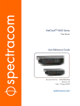
NetClock
®
9483
Time and Frequency Synchronization System
Option Card Installation Guide
1209-5000-0052 Rev.2, November 2016

Contents
Section A: Introduction – NetClock 9483 .................................................................................... 1
About this Document ................................................................................................................................. 1
Installation Overview .................................................................................................................. 2
Unpacking .................................................................................................................................................. 2
Safety ........................................................................................................................................ 2
Slots / Option Module Bays Layout ............................................................................................ 3
General Option Card Installation Instructions ............................................................................. 3
Section B: Specific Option Card Installation Instructions ............................................................ 5
Multi-Gigabit Ethernet Option Card Installation ......................................................................................... 5
T1/E1 – 120 Ohm Option Card Installation ............................................................................................... 5
PTP Option Card Installation ..................................................................................................................... 5
Reference Priority Input Configuration ................................................................................................... 6
Verifying HW Detection and SW Update .................................................................................... 7
Updating the System Software .............................................................................................................. 8
Technical and Customer Support ............................................................................................... 9

NetClock Spectracom
1 NetClock 9483 Option Card Installation Guide, Rev.2
Section A: Introduction – NetClock 9483
The NetClock® 9483 combines Spectracom’s precision Time Server / master clock technology and
secure network-centric approach with a fully NENA-compliant, compact modular hardware design to bring
you a powerful time & frequency reference system at the lowest cost of ownership.
NetClock 9483 is ideally suited for applications such as Emergency Communications Centers or
environments that require extremely accurate timing and frequency synchronization for their mission-
critical systems, networks, and devices. When using GPS as its timing reference, the UTC (Coordinated
Universal Time) time standard is employed, thus allowing the NetClock 9483 to provide legally traceable
time and frequency synchronization services for various related environments and equipment, such as
the following:
• 9-1-1 and PSAP communication center telephony
• Computer network synchronization
• VOIP / voice and video recording
• CAD
• ANI / ALI controllers
• Radio consoles and communications equipment
• Display clocks
• Security & building access systems, fire alarm systems
The NetClock 9483 also includes backwards-compatibility support with all previous generation NetClock
products; thus providing a bridge from legacy devices and equipment to network-based systems.
The NetClock 9483 series is a truly flexible Time Server / master clock, also supporting a variety of
timecodes (including all NENA formats) and signals to synchronize specific devices. The built-in network
port can be supplemented to include 3 additional Gigabit Ethernet (10/100/1000Base-T) ports for
synchronizing isolated networks, or for restricting administration to a specific management network.
Precise 10 MHz and 1 Pulse-per second (1PPS) signals are standard features, and additional optional
features include support for T1/E1 signals are available for synchronizing Telecom systems and
equipment, and Precision Timing Protocol (PTP) I/O support.
The unit is housed in a 19” rack unit chassis and offers an integrated power supply. DC power is available
as back-up to AC power, or as the primary input power source.
About this Document
This Option Card Installation Guide contains information and instructions for installing option module
cards in the NetClock 9483.

Spectracom NetClock
NetClock 9483 Option Card Installation Guide, Rev.2 2
Installation Overview
Unpacking
On receipt of materials, unpack and inspect the contents and accessories (retain all original packaging for
use in return shipments if necessary). The following additional items are included with the option card(s)
at shipment and may be required for installation depending upon your card type:
Item
Quantity
Part Number
50-pin ribbon cable
1
CA20R-R200-0R21
Washers
2
H032-0440-0002
Screws
4
HM11R-03R5-0004
Standoffs
2
HM50R-03R5-0018
Cable ties
2
MP00000
Additional Equipment Needed For Installation
In addition to the parts supplied with your option card, the following items are required for installation:
• #1 Philips head screwdriver
• Cable tie clipper
• 6mm hex wrench.
Safety
Before beginning any type of option card installation, please carefully read the following safety statements
and precautions to ensure that the NetClock unit has been safely and properly powered down (with all AC
and DC power cords disconnected). All installation instructions detailed henceforth in this document
assume that the NetClock unit has been powered down in this manner.
Always ensure that you adhere to any and all applicable safety warnings, guidelines, or precautions
during the installation, operation, and maintenance of your product.
WARNING
The interior of this equipment does not have any user serviceable parts. Contact
Spectracom Technical Support if this equipment needs to be serviced.
This unit will contain more than one power source if both the AC and DC power options are
present. Turning off the rear panel power switch will not remove all power sources.
Ensure all power sources are removed from the unit prior to installing any option cards by
removing both the AC and DC power cords connected to the equipment.

NetClock Spectracom
3 NetClock 9483 Option Card Installation Guide, Rev.2
Never remove the cover or blank option card plates with power applied to this equipment.
This equipment has Double Pole/Neutral Line Fusing on AC power.
CAUTION
Electronic equipment is sensitive to Electrostatic Discharge (ESD). Observe all ESD
precautions and safeguards when handling Spectracom equipment.
Slots / Option Module Bays Layout
Use the following figure as a reference of the rear panel slot layout of the NetClock 9483 unit.
The six option module bays are designated as Slot 1 – Slot 6, as shown:
Figure 1: NetClock 9483 rear panel option module bay slots
General Option Card Installation Instructions
IMPORTANT NOTE: Each of the available option cards must be installed into a specific Slot in the
NetClock 9483 unit in order to function properly (either Slot 2, or Slot 4). Refer to the table below to
determine the required installation Slot number for your option card, and then follow the installation
instructions outlined in the appropriate section for your option card.
Option Card Type:
Required Installation Slot:
Multi-port Gigabit Ethernet (Option 16 / PN 1204-06)
Slot 2
T1/E1 Outputs (Option 13 / PN 1204-0A)
Slot 4
PTP Input/Output (PN 1204-32)
Slot 4
Slot 1
Slot 3 Slot 5
Slot 2 Slot 4
Slot 6

Spectracom NetClock
NetClock 9483 Option Card Installation Guide, Rev.2 4
The following general instructions describe the steps required to install an option module card into Slot 2
or Slot 4 of a NetClock 9483 unit:
• Safely power down NetClock unit and remove chassis cover.
CAUTION:
NEVER install an option card from the back of the unit, ALWAYS from the top.
It is therefore necessary to remove the top cover of the main chassis (housing).
• Remove blank panel, or if existing option card already installed in top Slot 2 or 4, use screwdriver
to unscrew and remove the card from standoffs.
• If standoffs are not already installed, screw standoffs into the corners of the option cards
populating the bottom Slots.
• Insert your option card into the appropriate top Slot 2 or 4 depending upon option card type,
lining up the screw holes with the standoffs.
• Using the supplied screws, screw option card into the standoffs.
• Connect any required cables and secure option card into place.
• Replace chassis cover, power on the unit.
• Log in to NetClock web interface; verify the installed option card is identified by the NetClock.

NetClock Spectracom
5 NetClock 9483 Option Card Installation Guide, Rev.2
Section B: Specific Option Card Installation Instructions
This section includes detailed instructions and additional information specific to each individual option
card for installation.
Multi-Gigabit Ethernet Option Card Installation
NOTE: The Multi-Gigabit Ethernet option card must be installed in Slot 2. Also note that this card has its
own ancillary kit provided for installation.
• Safely power down NetClock unit and remove chassis cover.
CAUTION:
NEVER install an option card from the back of the unit, ALWAYS from the top.
It is therefore necessary to remove the top cover of the main chassis (housing).
• If standoffs are not already installed, screw standoffs into the corners of the module populating
bottom Slot 1.
• Insert the Multi-Gigabit option card into Slot 2 (lining up the card screw holes with the standoffs),
and using screwdriver, screw the option card into the standoffs.
• Connect any required cables and secure option card into place.
• Replace chassis cover, power on the unit.
• Log in to NetClock web interface; verify the installed option card is identified by the NetClock.
T1/E1 – 120 Ohm Option Card Installation
NOTE: The T1/E1 option card must be installed in Slot 4.
• Safely power down NetClock unit and remove chassis cover.
CAUTION:
NEVER install an option card from the back of the unit, ALWAYS from the top.
It is therefore necessary to remove the top cover of the main chassis (housing).
• If standoffs are not already installed, screw standoffs into the corners of the module populating
bottom Slot 3.
• Insert the T1 / E1 option card into Slot 4 (lining up the card screw holes with the standoffs), and
using screwdriver, screw the option card into the standoffs.
• Connect any required cables and secure option card into place.
• Replace chassis cover, power on the unit.
• Log in to NetClock web interface; verify the installed option card is identified by the NetClock.
PTP Option Card Installation
NOTE: The PTP option card must be installed in Slot 4.

Spectracom NetClock
NetClock 9483 Option Card Installation Guide, Rev.2 6
IMPORTANT NOTE: If installing the PTP option card, additional steps may be desired, depending upon
the NetClock’s Reference Priority Input configuration – refer to the following section.
Reference Priority Input Configuration
IMPORTANT NOTE: Adding or removing option module cards impacts the Reference Priority Input
configuration of the NetClock in the following manner:
When adding or removing option module cards with configured Input References, any user-defined
Reference Priority Input setup configuration will be reset. It is recommended to avoid this by taking the
following steps:
1. Save your current NetClock configuration.
2. Power down NetClock unit and install option card (outlined below).
3. Power up NetClock unit.
4. Restore the previously backed up NetClock configuration.
If these steps are not taken, the NetClock’s Reference Priority table will be reset back to the factory
default state for the NetClock hardware configuration, and the user / operator will need to reconfigure the
Reference Priority Table. For additional information on managing the Reference Priority Table, refer to
the NetClock 9400 Series Instruction Manual.
• Safely power down NetClock unit and remove chassis cover.
CAUTION:
NEVER install an option card from the back of the unit, ALWAYS from the top.
It is therefore necessary to remove the top cover of the main chassis (housing).
• If standoffs are not already installed, screw standoffs into the corners of the module populating
bottom Slot 3.
• Insert the PTP option card into Slot 4 (lining up the card screw holes with the standoffs), and
using screwdriver, screw the option card into the standoffs.
• Connect any required cables and secure option card into place.
• Replace chassis cover, power on the unit.
• Login to the NetClock web interface; verify the installed option card is identified by the NetClock.
• If you had backed up your NetClock configuration, optionally restore the previously saved
configuration (as previously noted).

NetClock Spectracom
7 NetClock 9483 Option Card Installation Guide, Rev.2
Verifying HW Detection and SW Update
Prior to beginning managing any features or functionality provided by the new card, it is advisable to
verify the successful installation by ensuring the new option module has been detected by the
NetClock unit.
(a) Re-install the top cover of the unit chassis (housing), using the saved screws.
(b) Power on the unit.
(c) Verify the successful installation by ensuring the option module has been detected:
NetClock Web UI, ≤ Version 4.x
Open a web browser, and log in to the NetClock web interface. Navigate to the STATUS/INPUTS
and/or STATUS/OUTPUTS pages. Information displayed on these pages will vary depending
upon your option module card/NetClock configuration (for example, the Multi-Gigabit Ethernet
option module card has both input and output functionality, and so is displayed in both pages).
NOTE:
If after an installation the card does not appear to be properly identified, it may be
necessary to update the NetClock system software to the latest available version.
Example STATUS/INPUTS page – NetClock Web UI
CAUTION:
Ensure that screw holes on the card are properly lined up and secured to the
chassis before powering the unit up, otherwise damage to the equipment may
result.

Spectracom NetClock
NetClock 9483 Option Card Installation Guide, Rev.2 8
Figure 14: Example STATUS/OUTPUTS page – NetClock Web UI
NetClock Web UI, ≥ Version 5.0
Open a web browser, log in to the NetClock Web UI, and navigate to INTERFACES > OPTION CARDS:
The new card will be displayed in the list.
• If the card does not appear to be properly identified, proceed with the System Software
update as described below, and then navigate to INTERFACES > OPTION CARDS again to
confirm the card has been detected.
• If the card has been detected properly, proceed with the Software update as described below
to ensure NetClock and the newly installed card are using the same, latest available version.
Updating the System Software
Even if the newly installed option card has been detected, and even if the latest System Software version
is installed on your NetClock unit, you must (re-)install the software to ensure both NetClock, and the
option card are using the latest software:
• Follow the System Software update procedure, as outlined in the main NetClock User Manual
under Software Updates
.
NEXT: Restore your reference priority configuration, as described in the following topic, and configure
other option card-specific settings, as described in the main User Manual.

NetClock Spectracom
9 NetClock 9483 Option Card Installation Guide, Rev.2
Technical and Customer Support
If you require further assistance with the configuration or operation of your product, or have questions or
issues that cannot be resolved using the information in this document, please contact Spectracom
Technical and Customer Support at either our North American or European service centers, or visit the
Spectracom website at www.spectracom.com
:
NOTE: Premium Support Customers can refer to their service contracts for emergency 24 hour support.
North America
Phone
+1 585.321.5800
email
techsupport@spectracom.com
Europe
France
Phone
+33 (0)1 6453 3980
email
techsupport-EMEA@spectracom.com
Document Revision History
Rev
ECN
Description
Date
A
3103
Initial document release.
December 2012
2
DOC-39
Added notes about chassis cover removal, and system software
update. General maintenance updates.
November 2016
/