Page is loading ...

Passionate about Music
w w w . B e t t e r M u s i c B u i l d e r . c o m
Thank you for purchasing this unit. To
make full and effective use of this unit,
please read this Owner's Manual
carefully before operating it. Please
retain this manual for future reference.
110421
UHF
Frequency Selectable
2-in-1 Base Module
***
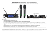
1 Receive Module with 2 Wireless Microphones System
UHF WIRELESS SYSTEM VM-52U G5
FREQ
MHz
UHF WIRELESS SYSTEM VM-52U G5
FREQ
MHz
PO WE R
SE T
MIN MA X
MI C 2
VO LUM E
MIN MA X
MI C 1
VO LUM E
SE T
VM-52U G5
UHF
2- IN-1 BASE RECE IVER MOD ULE
RF LEVEL
FREQUENCY
10 15 20 25 30 35 40
AF LEVEL
-25 -20 -15 -10 -5 0 PEAK
M
H
z
RF LEVEL
FREQUENCY
10 15 20 25 30 35 40
AF LEVEL
-25 -20 -15 -10 -5 0 PEAK
M
H
z
iR
Better Mus ic Bui lder
Professional UHF Wireless Microphone System
VM-52U G5
Operating Instructions
Better Music Builder .com
®
Passionate about Music
It’s what we do!

CONTENTS
INTRODUCTION................................................................................ 1
SYSTEM FEATURES............................................................................. 1
PACKAGE ACCESSORIES................................................................... 2
2-in-1 BASE MODULE........................................................................ 3
• Controls and Functions................................................................. 3~4
• Hardware Setup............................................................................. 5~7
HANDHELD MICROPHONE............................................................... 8
• Controls and Functions.................................................................. 8~9
• Auto-Power off System Features.................................................... 10
OPERATION............................................................................... 11~13
• How to Select Frequencies/Channels for the Receiver............... 11
• How to Match Receiver’s Frequency with Microphone............. 12
• How to Lock/Unlock The Display................................................... 12
• How to Change Batteries................................................................ 13
TECHNICAL SPECIFICATIONS.......................................................... 14
BODY-PACK MICROPHONE (Optional)...................................... 15~16
TROUBLESHOOTING................................................................. 17~18
APPENDIX................................................................................. 19~21
WARRANTY..................................................................................... 22
CONTACT INFORMATION............................................................... 23
hand-held
Base Module
Features
Package
Contact Us
Spec
Appendix
Warranty
Troubleshooting
Body-Pack
Intro
Operation

1
INTRODUCTION
Better Music Builder’s newest set of wireless microphones VM-52U G5 are a
huge improvement from the previous models, and greatly focusing on ease of
use and satisfaction.
The VM-52U G5 receiver is equipped with newer technologies that allow a
stronger signal strength and overall a greater range. The VM-52U G5 is
equipped with a more accurate IR sensor that makes selecting frequencies
much easier, reducing connectivity issues to a minimum. The handheld
microphones now have real-time battery indicators that updats frequently. A
new, unique machine etched design is added to the VM-52U G5 handheld
microphones for a better grip and feel.
SYSTEM FEATURES
• Smart Sensor integrated onto microphones.
• Auto-Mute Mode activates upon impact.
• Energy-efficient Sleep Mode.
• Equipped with the latest wireless technology UHF dual-channel 2-in-1 Base
Module.
• Clear LCD screen displaying Radio Frequency Level, Audio Frequency Level,
Frequency, Channel, Mute, and Lock.
• Wireless Infrared Auto Sync System.
• Manual and Auto Frequency Select.
• 200 selectable channels.
• Clear Voice technology delivers crystal clear sound.
• Adjustable antennas for better signal receiving.
• AA battery usage for easy handling.
• Up to 8 hours of battery life.
• Rack mountable.
Features
Intro

PACKAGE ACCESSORIES
The package comes with (1) 2-in-1 Base Module [Receiver], (2) handheld
microphones, (2) receiver antennas, (1) DC power adaptor, (1) unbalanced
audio 1/4” cable, and (4) AA batteries.
Package
2
AUDIO CABLE (FOR MIXED OUTPUT): 1 UNIT
For better connection, XLR to XLR
cable is recommended.
Recommend
AA
ALKA LINE
BATTER Y
AA
ALKA LINE
BATTER Y
AA
ALKA LINE
BATTER Y
AA
ALKA LINE
BATTER Y
AA (1.5V) BATTERY: 4 UNITS
DC POWER ADAPTOR: 1 UNIT
DC-POWER USAGE: This wireless
microphone system is designed specifically
for North America that uses 120V for DC
power. For usage in Asia or Europe, please
change it to 220V by an adaptor with DC
14V output 500mA.
NOTE
2-IN-1 BASE MODULE [RECEIVER]: 1 UNIT
HANDHELD MICROPHONE: 2 UNITS
RECEIVER
ANTENNA:
2 UNITS
10.2 inches
25.8 cm
UHF WIRELESS SYSTEM VM-52U G5
FREQ
MHz
UHF WIRELESS SYSTEM VM-52U G5
FREQ
MHz
POWER
SE T
MI N MAX
MI C 2
VOL UME
MI N MAX
MI C 1
VOL UME
SE T
2- IN-1 B ASE R EC EI V ER M OD UL E
VM-52U G5
UHF
iR
Better Music Builder
RF LEVEL
FREQUENCY
10 15 20 25 30 35 40
AF LEVEL
-25 -20 -15 -10 -5 0 PEAK
M
H
z
RF LEVEL
FREQUENCY
10 15 20 25 30 35 40
AF LEVEL
-25 -20 -15 -10 -5 0 PEAK
M
H
z
Base Module
3
2-in-1 BASE MODULE [RECEIVER]
CONTROLS AND FUNCTIONS
FRONT PANEL:
1. POWER BUTTON: Turns the system on/off.
2. MIC 1 VOLUME CONTROL: Controls Microphone 1 volume.
3. MIC 1 SELECTOR BUTTONS (UP/SET/DOWN): Allows control of LCD
screen and functions for Microphone 1.
4. LCD SCREEN: Displays system status.
5. IR PORT: Infrared port for the Wireless Infrared Auto Sync System. Pointing
the handheld microphone’s infrared port at the receiver’s infrared port to
allow communication.
6. MIC 2 SELECTOR BUTTONS (UP/SET/DOWN): Allows control of LCD
screen and functions for Microphone 2.
7. MIC 2 VOLUME CONTROL: Controls Microphone 2 volume.
1 2 73 64 5

LCD PANEL:
After turning on the “POWER”, LCD screen will display the following:
8. RADIO FREQUENCY LEVEL: Strength indicator of radio signal.
9. AUDIO FREQUENCY LEVEL: Strength indicator of incoming audio signal.
10. MUTE: Indicates if microphone is powered off.
11. FREQUENCY & CHANNEL: Displays current frequency and channel.
REAR PANEL:
12. ANTENNA-A: Connect the antenna to the BNC socket.
13. POWER SUPPLY: For power adapter with DC12~18V 500mA.
14. MIC 2 BALANCED OUTPUT: Balanced XLR audio output.
15. MIXED OUTPUT: Unbalanced 1/4" audio output for MIC 1 & MIC 2.
16. MIC 1 BALANCED OUTPUT: Balanced XLR audio output.
17. ANTENNA-B: Connect the antenna to the BNC socket.
4
RF LEVEL
FREQUENCY
10 15 20 25 30 35 40
AF LEVEL
-25 -20 -15 -10 -5 0 PEAK
M
H
z
RF LEVEL
FREQUENCY
10 15 20 25 30 35 40
AF LEVEL
-25 -20 -15 -10 -5 0 PEAK
M
H
z
8
9
10
11
TRUE DIVERSIT Y
MIX
MIC 1 & 2
UNBA L
ANC ED
AU DIO OU TPUT
MIC 2 BALANCED MIC 1 BALANCED
ANTENN A-A
ANTENN A-B
DC 12-18V
DC-POWER
RISK OF ELEC TRIC SHOCK
DO NOT OPEN
Model No.: V M-52U G5
CALIFORNIA, UNITED STATES OF AMERICA
w w w. B e tt erMus i c B u i l d e r. co m
ENGINEERED AND DESIGNED IN U.S.A.
394161105000
SERIAL NO.
12 1713 1514 16

5
TRUE DIVERSIT Y
MIX
MIC 1 & 2
UNBA L
ANC ED
AU DIO OU TPUT
MIC 2 BALANCED MIC 1 BALANCED
ANTENN A-A
ANTENN A-B
DC 12-18V
DC-POWER
RISK OF ELEC TRIC SHOCK
DO NOT OPEN
Model No.: V M-52U G5
CALIFORNIA, UNITED STATES OF AMERICA
w w w. B e tt erMus i c B u i l d e r. co m
ENGINEERED AND DESIGNED IN U.S.A.
394161105000
SERIAL NO.
Set Up
HARDWARE SETUP
HOW TO CONNECT AUDIO OUTPUT:
There are three rear audio outputs as shown in the below diagram:
1. Mic 2 Balanced Output
Mic 2 Balanced Output is balanced audio output for MIC 2 using XLR
connection. When using this output, you can control MIC 2 effects without
affecting MIC 1 effects.
2. Mic 1 Balanced Output
Mic 1 Balanced Output is balanced audio output for MIC 1 using XLR
connection. When using this output, you can control MIC 1 effects without
affecting MIC 2 effects.
3. Mixed Output
Mixed Output is unbalanced audio output for MIC 1 & MIC 2 using 1/4”
connection. When using this output, MIC 1 and MIC 2 are sharing one
signal. To produce different effects on the two microphones, MIC 1 and MIC
2 need independent signals using separate XLR connections.
We highly recommend using balanced XLR connections if the distance between the
microphone receiver and the mixer is more than 10 feet. The grounding of the
balanced XLR connection delivers better quality signal by reducing noise.
Recommend
1
MIC 2 BALANCED OUTPUT
(BALANCED XLR)
3
MIXED OUTPUT
(MIC 1 & 2 UNBALANCED)
MIC 1 BALANCED OUTPUT
(BALANCED XLR)
2

6
TRUE DIVERSIT Y
MIX
MIC 1 & 2
UNBA L
ANC ED
AU DIO OU TPUT
MIC 2 BALANCED MIC 1 BALANCED
ANTENN A-A
ANTENN A-B
DC 12-18V
DC-POWER
RISK OF ELEC TRIC SHOCK
DO NOT OPEN
Model No.: V M-52U G5
CALIFORNIA, UNITED STATES OF AMERICA
w w w. B e tt erMus i c B u i l d e r. co m
ENGINEERED AND DESIGNED IN U.S.A.
394161105000
SERIAL NO.
XLR
Balanced Input
XLR
Balanced Input
XLR
Balanced Input
XLR
Balanced Input
1/4"
Unbalanced Input
1/4"
Unbalanced Input
1/4"
Unbalanced Input
1/4"
Unbalanced Input
UHF WIRELESS SYSTEM DIAGRAM:
BALANCED CONNECTION
MIXER AMPLIFIER OR KARAOKE UNIT INPUT TERMINAL
REAR VIEW
MIC 2 HANDHELD MICROPHONEMIC 1 HANDHELD MICROPHONE
HOW TO CONNECT DC-POWER:
For North America Market, use 120V, DC 12~18V 300mA~500mA power
adaptor. For Asia or Europe, use 220V~ 240V DC power adaptor with a
maximum battery capacity of 300mA~500mA.
NOTE
Please make sure to use the correct DC power adaptor. Otherwise, it may damage the
2-in-1 Base Module and/or the charger because their maximum battery capacity is different. The
warranty will be voided if product is damaged using the wrong DC power adaptor.
REAR VIEW
UHF WIRELESS SYSTEM VM-52U G5
FREQ
MHz
UHF WIRELESS SYSTEM VM-52U G5
FREQ
MHz

7
OPTIONAL 19” RACK MOUNT KIT:
To put the system onto one of the mount kits, please follow the diagram below.
Single Receiver Rack Mount Kit
Dual Receiver Rack Mount Kit
10 inches
19 inches
13.8 inches
Rack mount kit is not included in package.
ANTENNA IS
ADJUSTABLE
10 inches
19 inches
8.2 inches 5.4 inches5.4 inches
Rack mount kit is not included in package.
ANTENNA IS
ADJUSTABLE
POW ER
SET
MIN MA X
MIC 2
VOL UME
MIN MA X
MIC 1
VOL UME
SET
VM-52U G 5
UHF
2-IN -1 B ASE R ECEI VER MODU LE
RF LEVEL
FREQUENCY
10 15 20 25 30 35 40
AF LEVEL
-25 -20 -15 -10 -5 0 PEAK
M
H
z
RF LEVEL
FREQUENCY
10 15 20 25 30 35 40
AF LEVEL
-25 -20 -15 -10 -5 0 PEAK
M
H
z
iR
Bette r Music Bu ilder
POW ER
SET
MIN MA X
MIC 2
VOL UME
MIN MA X
MIC 1
VOL UME
SET
VM-52U G 5
UHF
2-IN -1 B ASE R ECEI VER MODU LE
RF LEVEL
FREQUENCY
10 15 20 25 30 35 40
AF LEVEL
-25 -20 -15 -10 -5 0 PEAK
M
H
z
RF LEVEL
FREQUENCY
10 15 20 25 30 35 40
AF LEVEL
-25 -20 -15 -10 -5 0 PEAK
M
H
z
iR
Bette r Music Bu ilder
POW ER
SET
MIN MA X
MIC 2
VOL UME
MIN MA X
MIC 1
VOL UME
SET
VM-52U G 5
UHF
2-IN -1 B ASE R ECEI VER MODU LE
RF LEVEL
FREQUENCY
10 15 20 25 30 35 40
AF LEVEL
-25 -20 -15 -10 -5 0 PEAK
M
H
z
RF LEVEL
FREQUENCY
10 15 20 25 30 35 40
AF LEVEL
-25 -20 -15 -10 -5 0 PEAK
M
H
z
iR
Bette r Music Bu ilder

LOHI
FREQ
MHz
UHF WIRELESS SYSTEM VM-52U G5
FREQ
MHz
8
Hand-held
1 3 4
6
2
AA
ALKALINE
BATTERY
AA
ALKALINE
BATTERY
HANDHELD MICROPHONE
CONTROLS AND FUNCTIONS
1. INTERCHANGEABLE MICROPHONE HEAD
2. LCD DIGITAL DISPLAY: Displays frequency, and battery status.
3. IR PORT: Infrared port for the Wireless Infrared Auto Sync Technology.
Point the microphone’s infrared port at the receiver’s infrared port to allow
communication.
4. POWER BUTTON
5. TRANSMISSION POWER LEVEL SWITCH
6. BATTERY COMPARTMENT: Insert 2x1.5V AA battery or 2x1.2V
rechargeable AA battery.
5

FREQ
MHz
9
LCD PANEL:
After turning on the “POWER”, the LCD screen will light up as below:
1. FREQUENCY: Current value depends on setting.
2. BATTERY STATUS: Indicates battery life.
BATTERY STATUS:
1
2
Indicates full battery on the microphone. A full
battery lasts up to 8 hours.
Batteries are not covered under our product warranty.
NOTE
Low Battery
Full Battery
LCD screen blinks when
battery is extremely low.
Indicates low battery on the microphone.
When the microphone LCD screen is blinking.
it’s time to replace the batteries.
FREQ
MHz
FREQ
MHz
FREQ
MHz

10
AUTO-POWER OFF SYSTEM FEATURES
This function’s primary focus is to eliminate unwanted noise while being energy
efficient. To do so, the microphones are equipped with a Smart Sensor.
FEATURES:
1. Energy Saving
The microphone minimizes power consumption by entering Sleep Mode
after 20 seconds, allowing for more usage time without changing batteries.
2. Anti-Howl & Noise
To eliminate unwanted noise when the microphone is dropped, the six-axis
gyroscope sensor is used to detect a fast change in motion. The sensor
detects whether the motion is intended or not by the elapsed time it is falling.
When the time exceeds an estimated drop, the microphone signal then cuts
off momentarily; so at the point of impact the microphone is no longer
sending any signal to the receiver.
3. Auto-Power Off
The microphone detects and automatically shuts off when it is dropping. This
function can avoid most unwanted noise and greatly decrease the chances
of any damage to the audio equipment. It is important to note the
Auto-Power Off function will engage once the sensor detects a falling
motion. The approximate falling distance for the sensor to activate is
12 inches/30 cm.
Ground
12 inches/30 cm
UHF WIRELESS SYSTEM VM-52U G5
FREQ
MHz

11
Operation
OPERATION
HOW TO SELECT FREQUENCIES/CHANNELS FOR THE RECEIVER
The 2-in-1 Base Module comes with two handheld microphones and each
microphone is preset with 100 frequency channels. The frequency can be
selected either automatically or manually.
1. AUTOMATIC FREQUENCY/CHANNEL SELECT
Press and hold “DOWN ▼” until “ ” displays. Then the best frequency
will be selected.
2. MANUAL FREQUENCY/CHANNEL SELECT
STEP 1: Press and hold “UP ▲” on the receiver untile the channel blinks.
STEP 2: While the channel is blinking, press “UP ▲ or DOWN ▼” to select the
desired channel. Then press “SET” to confirm the channel.
SET
iR
RF LEVEL
FREQUENCY
10 15 20 25 30 35 40
AF LEVEL
-25 -20 -15 -10 -5 0
PEAK
M
H
z
RF LEVEL
FREQUENCY
10 15 20 25 30 35 40
AF LEVEL
-25 -20 -15 -10 -5 0
PEAK
SET
iR
RF LEVEL
FREQUENCY
10 15 20 25 30 35 40
AF LEVEL
-25 -20 -15 -10 -5 0
PEAK
M
H
z
RF LEVEL
10 15 20 25 30 35 40
AF LEVEL
-25 -20 -15 -10 -5 0
PEAK
SET
iR
RF LEVEL
FREQUENCY
10 15 20 25 30 35 40
AF LEVEL
-25 -20 -15 -10 -5 0
PEAK
M
H
z
RF LEVEL
FREQUENCY
10 15 20 25 30 35 40
AF LEVEL
-25 -20 -15 -10 -5 0
PEAK
M
H
z
SET
iR
RF LEVEL
FREQUENCY
10 15 20 25 30 35 40
AF LEVEL
-25 -20 -15 -10 -5 0
PEAK
M
H
z
RF LEVEL
FREQUENCY
10 15 20 25 30 35 40
AF LEVEL
-25 -20 -15 -10 -5 0
PEAK
SET
iR

12
Please make sure that the
other handheld microphone is
powered off when adjusting the
frequency on one microphone.
Each unit is fully tested and qualified
by the manufacturer. However, due
to the nature of wireless connection,
interference may occur because of
local environments and/or radio
signals emitted by other wireless
devices within the household.
NOTE
HOW TO MATCH RECEIVER’S FREQUENCY WITH MICROPHONE
STEP 1: Turn ON the microphone, point the microphone infrared port (IR) directly
at the receiver’s IR PORT.
STEP 2: Press and hold “SET” until “1A - - - - ” displays. Once syncing is
completed, the RF level bar appears and the “MUTE” icon disappears.
HOW TO LOCK/UNLOCK THE DISPLAY
Press and hold “UP ▲” and “DOWN ▼” at the same time to lock/unlock the
setting.
POW ER
SET
MIN MAX
MIC 2
VOL UME
MIN MAX
MIC 1
VOL UME
SET
RF LEVEL
FREQUENCY
10 15 20 25 30 35 40
AF LEVEL
-25 -20 -15 -10 -5 0 PEAK
M
H
z
RF LEVEL
FREQUENCY
10 15 20 25 30 35 40
AF LEVEL
-25 -20 -15 -10 -5 0 PEAK
M
H
z
2-IN -1 BA SE R ECEI VER MODU LE
VM-52U G 5
UHF
iR
Bette r Music Bui lder
UHF WIRELESS SYSTEM VM-52U G5
FREQ
MHz
Maximum Frequency
Matching Distance: 10 feet
S
YN
CI
NG
PR
O
C
ES
S
SE T
iR
RF LEVEL
FREQUENCY
10 15 20 25 30 35 40
AF LEVEL
-25 -20 -15 -10 -5 0 PEAK
M
H
z
RF LEVEL
FREQUENCY
10 15 20 25 30 35 40
AF LEVEL
-25 -20 -15 -10 -5 0 PEAK
M
H
z
SE T
iR
RF LEVEL
FREQUENCY
10 15 20 25 30 35 40
AF LEVEL
-25 -20 -15 -10 -5 0 PEAK
M
H
z
SET
iR
RF LEVEL
FREQUENCY
10 15 20 25 30 35 40
AF LEVEL
-25 -20 -15 -10 -5 0
PEAK
M
H
z
RF LEVEL
FREQUENCY
10 15 20 25 30 35 40
AF LEVEL
-25 -20 -15 -10 -5 0
PEAK
SET
iR
RF LEVEL
FREQUENCY
10 15 20 25 30 35 40
AF LEVEL
-25 -20 -15 -10 -5 0
PEAK
M
H
z
RF LEVEL
FREQUENCY
10 15 20 25 30 35 40
AF LEVEL
-25 -20 -15 -10 -5 0
PEAK
SYNCING
PROCESS

13
HOW TO CHANGE BATTERIES
STEP 1: Twist open battery cover.
STEP 2: Use one hand to hold onto the top of the microphone and the other
hand slide two AA batteries into battery compartment.
Make sure to follow the polarity of the battery according to the diagram
on battery compartment.
STEP 3: Twist back battery cover.
Good
AA
ALKALINE
BATTERY
AA
ALKALINE
BATTERY
No Good
AA
ALKALINE
BATTERY
AA
ALKALINE
BATTERY
AA
ALKALINE
BATTERY
UHF WIRELESS SYSTEM VM-52U G5
UHF WIRELESS SYSTEM VM-52U G5

14
TECHNICAL SPECIFICATIONS
A. TECHNICAL FEATURE OF THE 2-IN-1 BASE MODULE (Receiver):
• Channel: 200 Channels
• Frequency Range: UHF 480.100~529.850 MHz
• Modulation Method: /4 -DQPSK
• Sampling Ratio: 48kHz
• Transmission Rate: 204.8Kbps
• Dynamic Range: > 90dB
• Total Harmonic Distortion: < 0.1%
• Delay Time of Audio Transmission: <3ms
• S/N Ratio: >96dB
• Frequency Response: 30~20kHz
• RX Sensitivity: < –94dBm
• Unique ID Address: YES
• Audio Output: 2 x XLR Port
• Power Supply: DC 12V~18V with 500mA, AC 120V
(For 220V, change to a 220V~240V DC power adaptor)
• Receiver Dimensions (WxHxD): 8.7 x 2 x 7.1 (inches) / 22 x 5 x 18 (cm)
• Package Dimensions (WxHxD): 15.6 x 12.2 x 2.7 (inches) / 39.5 x 31 x 6.8 (cm)
• Shipping Weight: 4.6 lbs / 2.1 kg
B. THIS SYSTEM INCLUDES THE FOLLOWING:
• 2-in-1 Base Module [Receiver]: 1 Set
• Handheld Microphone: 2 Sets
• DC Power Adaptor: 1 Unit
• 1/4” Audio Cable: 1 Unit
• Receiver Antenna: 2 Units
• AA 1.5V Battery: 4 Units
• Instructional Manual: 1 Unit
• Warranty & Registration Card: 1 Unit
Specs

15
BODY-PACK MICROPHONE SYSTEM (Optional)
SPECIFICATIONS:
NAMES & FUNCTION:
Body-Pack Microphone System (including Lavalier Mic. and Headset Mic.)
Optional
SIDE VIEW
TOP VIEW
1. Antenna Jack
2. Power/Mute indicator
3. Power Switch
4. Microphone Input Jack
1 2 3 4
Optional
Optional
Headset Mic.
1/4” to mini 3-pin lavalier cable
Lavalier Mic.
1/4” to mini 3-pin lavalier cable
Optional
FRONT VIEW
1. Antenna
2. 4-pin Microphone Input Jack
3. LCD Digital Display
4. IR Port: Receives infrared beam
to synchronize frequencies. IR
when using multiple systems,
only one microphone port should
be exposed at a time
5. Battery Cover
6. Tie-Clip
7. Microphone Extension Jack
INSIDE VIEW
1. Power/Mute indicator
• Green: Ready
• Amber: Mute Open
• Flashing Red: IR is transmission in
process
• Glowing Red: Low battery power
• Pulsing Red: Battery dead
(microphone cannot be turned off
until batteries are changed)
2. Power ON/OFF/MUTE Button:
Press and hold the microphone
for 3 seconds to turn power
ON/OFF. Press and release to
mute or un-mute the microphone.
3. Adjustment switch
4. Battery compartment
7
1
2
3
4
5
6
Optional
2
1
4
3
Optional
Body-Pack

16
HOW TO CHANGE BODY-PACK BATTERIES
HOW TO WEAR BODY-PACK
The Body-Pack can be buckled to the belt or the guitar band.
ADJUSTMENT GAIN
Three gain settings are available.
Choose the appropriate setting for your
instrument.
• MIC: for the microphone adjustment
• 0: Guitar with passive pickups
• -10: Guitar with active pickups
BODY-PACK REAR VIEW
A
AA
ALKALINE
BATTERY
AA
ALKALINE
BATTERY
AA
ALKALINE
BATTERY
Good
CLOSE
OPEN
STEP 1: Open battery cover.
STEP 2: Insert 2 AA batteries. 2
alkaline batteries are expected to
last 8 hours.
Make sure to insert batteries
correctly according to diagram.
When the microphone body-pack
light glows red, the batteries should
be changed immediately.
1
2
BODY-PACK REAR VIEW
B

17
TROUBLESHOOTING
CAUTION: Before troubleshooting any symptoms make sure the
equipments are in the “OFF” position.
1. SYMPTOM: NO SOUND COMING FROM MICROPHONE
A. CAUSE: There is no signal.
a. Check if batteries are inserted correctly.
b. If batteries are inserted correctly but still no power, insert new batteries
c. Make sure the microphone and receiver are in the same channel.
d. The volume may be turned to a low level.
B. CAUSE: The receiver is unpowered.
Make sure the power adapter is connected properly and there is power
coming from the power outlet.
C. CAUSE: There is no AF signal.
Turn off the receiver and make sure it is properly connected to the mixer or
amplifier. If it is, slowly turn the volume higher.
D. CAUSE: There is no indication of RF signal.
There may be interference so change to different channels. Adjust the antenna
of the receiver and/or remove objects between receiver and microphone .
2. SYMPTOM: NOISE COMING FROM MICROPHONE
CAUSE: There are interference within your area.
1. Change the channel on the microphone and receiver.
2. Stand further away from speakers.
3. SYMPTOM: THE MICROPHONE SUDDENLY HAS NO SOUND AND THE
RECEIVER LCD IS OFF.
Make sure the AC power adapter is properly connected to the receiver and
securely plugged into the electrical outlet. Make sure the AC electrical outlet
works and supplies the proper voltage.
Troubleshooting

18
4. SYMPTOM: THE MICROPHONE SUDDENLY HAS NO SOUND BUT THE
RECEIVER SHOWS RF SIGNAL.
CAUSE: The microphone wire is damaged or disconnected.
To fix it, open the microphone head cover to check the wire and reconnect the
wire. If it does not work, replace the microphone head.
5. SYMPTOM: THE MICROPHONE DISTORTION LEVEL IS INCREASING
GRADUALLY.
CAUSE: The microphone batteries are running out.
lowReplace the microphone batteries.
6. SYMPTOM: POOR SIGNAL
CAUSE: When the 2-in-1 Base Module and microphone are placed in different
rooms seperated by a wall, this would cause poor signal.
Your audio equipment is close to the police, fire or radio stations. In this case,
a different frequency MUST be selected.
7. SYMPTOM: THE FREQUENCY OF THE MICROPHONE IS DIFFERENT
FROM THE RECEIVER.
The microphone’s frequency must match withreceiver’s frequency.
/