Page is loading ...

1
1-18
QUICK LIFT L520E
EN
Operating and control manual for a lifting platform
User manual
French version
Made in China:
Yantai Tonghe Precision Industry Co.,Ltd
www.ytthjg.com
Imported by:
GYS FRANCE
www.gys.f r

2
DIMENSIONS
DIMENSIONS
A
Boom length in min. position 1 746 mm
B Height min 88 mm
C
Boom length in max. position 1 468 mm
D Maximum lifting height (with chock) 460 mm
E Width 315 mm
FEATURES
Maximum Load 2 500 kg 1250Kg/ramp
Safety in case of mechanical fall YES (2 positions)
Electrical installation 220 V AC (50/60Hz)
Hydraulic tank capacity 4L
Noise level < 70dA
A
scent and descent times 20 to 30 seconds
Protection rating IP20
E
Flat ramp
Max. ramp position / weight 39kg
Hydraulic power pack/
weight 20kg

3
Safety and functional check
Carried out by the manufacturer according to the following data:
The following elements are present:
Technical nameplate on the product
Instructions for use
Max. load capacity
Raise "UP", lower "DN" on the wired control unit.
CE identification
Controlled operation and safety:
Pressure relief valve set at 180 bars
Verify:
No-load function test over a complete cycle
Operation of the mechanical safety devices and the emergency stop button
Controls automatically return to initial position
No damage to the cylinders, the power supply cable, and the wired remote control cable
Tight fastening of all bearing screws
Condition of the hydraulic hoses (tightness and tightness of all connections)
Full cycle load operation
Serial number:_________________
Date:______________________
Name:______________________
EC Declaration of Conformity
LUXMAIN
Yantai Tonghe Precision Industry Co Ltd
N° 151 Xili Industrieanal Park, Zhifuqu
Country: China
City: Yantai

4
The builder
Yantai Tonghe Precision Industry Co Ltd
N° 151 Xili Industrieanal Park, Zhifuqu
China
Responsible for
documentation
Yantai Tonghe Precision Industry Co Ltd
Hereby declares that the
machine named herein
Elevating
platform
Type
Quick Lift
Reference
L520E
Serial No
(See page 3)
Corresponds to the safety
requirements in the following
EC directives
EC Machinery Directive
2006/42/EC
Directive 201165/EU, RoHS2,
of 2011.06.08
EC Certificate of Conformity EN1493: 2010 EN50581: 2012
Report No. 185226910101 NGBEC1802310202
Control body INSPECCO BELGELENDIRME
VE GOZETIM HIZMETLERI
A.S
ID number 2459
NINGBI QIAOPU ELECTRIC
CO.,LTd
Xiaoluxia Village, Simen Town,
Yuyao City, Zhejiang, China
This declaration of conformity becomes null and void if the design changes specified in the operating
instructions have an effect on the technical data and the intended use of the machine and thus
significantly alter the machine!
Thank you for choosing GYS! In order to obtain maximum satisfaction from your QUICK LIFT lifting platform and for
Mr Wang
C.E.O
Yantai,
15/02/2019

5
your safety, please read these operating instructions carefully before first use and keep them in a safe place for future
reference.
BACKGROUND INFORMATION
These operating instructions contain important information for installation in order to ensure proper commissioning
and operational safety of the QUICK LIFT. Complying with the documentation reduces risks and extends the life of the
product. This manual contains a form to certify regular security checks. Use the "Regular Security Check" form to
archive the checks. (It is advisable to make a copy of the form before filling it in for the first time.)
Installation and control:
Safety work and safety checks are reserved exclusively for specially trained persons. These persons are referred to in
this documentation as experts and/or authorised persons.
LIABILITY LIMITATIONS
The QUICK LIFT is a manually operated mobile hydraulic lift designed in compliance with standards. All data and
advice given in these instructions for use have been collected taking into account these applicable standards and
regulations as well as our extensive knowledge and experience.
The manufacturer cannot be held responsible in case of material and physical damage that could lead to
death by:
1- Non-observance of the instructions for use
2- Improper or dangerous use
3- Employment of unskilled persons
4- Unauthorized processing on QUICK LIFT
5- Insufficient maintenance
INTENDED INTENDED USE
The QUICK LIFT is designed for the repair of passenger vehicles. It allows the bodybuilder to lift vehicles safely. The
maximum load of the QUICK LIFT is 2500 kg.
The QUICK LIFT may only be used by persons who have read and understood the operating instructions.
A safety perimeter must be defined in which no one must be present during the lifting operation (minimum 2m around
the vehicle to allow escape if necessary).
The lifting of persons or other objects is not allowed. No one must be inside the vehicle to be lifted.
The QUICK LIFT must be used inside a work room and protected from bad weather (IP 20, wind, rain and negative
temperature).
The operating temperature range is between 5°C and 60°C maximum. In case of prolonged storage in a place where
the temperature is below 0°C, allow at least 12 hours before use by storing it in the workplace.
Do not use in excessively humid conditions.
This equipment is delivered with a 16 A CEE7/7 type plug and must only be used on a single-phase 220 V (50 - 60 Hz)
electrical installation.
Never lift loads on sloping ground (>3°). The floor must be flat and strong enough to prevent the QUICK LIFT from
sinking under the weight of the load (35kg/cm²). Under no circumstances should the Quick Lift be placed on an
inspection hatch on the floor.
It is forbidden to use the QUICK LIFT on a boat/vessel (stability problem).
Thoroughly clean the supporting surface of the vehicle and the rubber pads of the QUICK LIFT before each use.
Remove all grease and oil stains that could cause the vehicle to slip.
Work underneath the vehicle during ascent and descent is not permitted.
Vehicles should only be lifted at the lifting points recommended by the car manufacturers. Make sure that the QUICK

6
LIFT does not come into contact with areas close to the airbag activation sensors during and after the climb.
Do not place the rubber spacers on an area with plastic lining.
Take care of electrical cables and hydraulic hoses, do not crush them or step on them.
In the event of a violent impact on the load-bearing and/or structural elements of the QUICK LIFT, it is imperative to
take the product out of service and contact your dealer or the manufacturer in order to assess the damage before
putting it back into service.
In case of doubt about the strength of the vehicle structure (presence of rust) - Do not lift the vehicle.
Intended use also includes familiarising yourself with these operating instructions and complying with all the
instructions contained therein, in particular the safety instructions.
Enforce safety and risk prevention standards in the country's workplaces.
In addition, this also includes the obligation to carry out all regular inter-wall inspection and maintenance work.
In the event of improper use of the lift, the operational safety of the QUICK LIFT is not guaranteed.
Damage to persons and property, also on vehicles, caused by improper use of the device is in no way the
responsibility of the manufacturer, but of the operator handling the QUICK LIFT.
QUICK LIFT must not be used in a potentially explosive atmosphere and it is not recommended to work next to a heat
source.
It is forbidden to use spare parts other than original parts certified by the manufacturer.
Make sure that your QUICK LIFT is in one of the two locked positions before you start working around or underneath.
At the end of a work session, return the vehicle to the ground to avoid operating the QUICK LIFT with a full load for a
long period of time.
PACKAGING AND UNLOADING
The QUICK LIFT is packed in two parcels on a pallet. In a pocket on the outside of the package you will find the
QUICK LIFT operating and testing instructions. The larger package contains the two booms and accessories and in the
smaller package is the hydraulic power pack. On delivery, check for external transport damage. In case of visible
damage, leave the goods and packaging as they are. Do not use the goods and contact your dealer directly. Failing
this, a reservation must be made to the carrier. Unloading is done by means of a pallet truck or a forklift truck.
INDIVIDUAL COVERAGE
The operator must be equipped in accordance with the occupational risk prevention standards applicable in his
country and must adopt all necessary measures to maintain safety at his workstation. During manoeuvres, the
operator must ensure his own safety and that of the people and objects around him. The operator must take into
consideration all the recommendations quoted in this manual.
Hydraulic fluid is dangerous if splashed in the eyes or if it comes into
contact with blood. In this case, contact your doctor immediately. Never
reach over your hand to check for a hydraulic leak: risk of cut and
contamination in the bloodstream that could lead to death.
START UP
Make sure you have the necessary protection: pair of glasses, safety shoes and gloves.
Step 1: Lay the two booms on the ground parallel by aligning the hydraulic hoses.
The ramps are very similar but they are not interchangeable.. The mechanical
safety must always be on the outside and the ramps pointing in the same
direction.

7
Castors are provided on the QUICK LIFT to move the ramps easily and to allow them to be properly positioned under
the vehicle. Use the handles to carry the ramps one by one more easily.
Step 2: Place the hydraulic power pack at least 2 meters away from the ramps without connecting it
electrically. Attach the long hydraulic hoses to the hydraulic power pack. Do not overtighten, the sealing
is done automatically with the conical seat of the connections.
Step 3: The tank of the hydraulic unit is empty. It must be filled with hydraulic oil or automatic
transmission fluid before starting operation. Approved fluids are general purpose hydraulic oils or
synthetic automatic transmission oils with a viscosity index of 32 cSt at 40°C.
Remove the fuel filler cap and fill it with up to 3.5L of oil through a clean funnel. Check the level and adjust if
necessary.
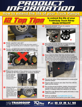
Electrical outlet
Wired telecom
H
y
draulic
p
ower
p
ack
Long hydraulic hoses (X2)
Casters
Locking bar
(On the outside)
Locking bar
(On the outside)
Short hydraulic hoses (X2)
Transport
handles

8
Step 4: Connect the hydraulic power pack to both booms using the quick couplings.
Step 5: Check that the electrical system is equipped with a 16 A circuit breaker. Connect the hydraulic
unit electrically to a 220V single-phase socket, your QUICK LIFT is ready to operate.
SAFTEY AREA
To achieve optimum safety, it is recommended to define an area in which other objects or walls
will be at a certain distance (2m minimum). All descent, exit and parking manoeuvres must be
carried out with the best possible attention from the operator. Nobody must be stand in the
safety area. In order to guarantee the operator's safety, the control box must be located at a
distance that allows an escape route in case of emergency.
INSTALLATION
Once the tool has been removed from its packaging, assembled and positioned on the ground, perform a no-load test
to check the QUICK LIFT's general operation.
There are two positions for locking the height of the QUICK LIFT, which we will call height 1 and height 2 (max.
height) in the rest of the manual.
First of all, the QUICK LIFT must never be lifted unladen (without load) to the
maximum stop. The ramps could get stuck and never come down again. They are
designed to support a load during lifting. If this happens to you, please refer to
the paragraph "Abnormalities, Causes, Remedies".
Make sure you have the necessary protection: pair of glasses, safety shoes and gloves.
1/ IDLE START:
Connect the power cord of the hydraulic unit to a 220 V single-phase socket.
2/ CHECKING THE AMOUNT: use the wired remote control
a. Press the "UP" button until the QUICK LIFT rises a few centimetres (5 to 10 cm max.).
Height 1 Height 2
Hei
g
ht 1
Hei
g
ht 2
Locking bar in locked position
height 1

9
b. Visually check all hydraulic connections (cylinders, hoses, couplings, power pack) for hydraulic leakage. If you notice a slight
leak, tighten the connection until there is no more leakage. If you see a large leak, immediately press "DN" (down) until the
QUICK LIFT is lowered to the ground. Tighten the connection firmly and repeat the test until there is no more leakage.
It is advisable to place a cardboard box between the floor and the QUICK LIFT
and even at the level of the quick connections in order to identify possible leaks
more easily during the first start-up.
Be meticulous when applying a sealing tab or Teflon to hydraulic connections. Do
not pollute or clog the hydraulic system. There are filters that could become
clogged and prevent the QUICK LIFT from working properly.
3/ CHECKING THE SAFETY SYSTEM AT HEIGHT 1:
Press "UP" again and move a few centimetres higher than height 1 so that the safety devices of both ramps protrude
a few centimetres above the locking block at height 1.
When empty, there may be a greater offset in the height of the ramps in relation
to each other and therefore in the passage of the locking bars on the blocks. This
is normal. On load, the ramps will be synchronized and the offset will be
corrected.
Pressing "DN" (down) will lower the ramps until both locking levers are in the locked position as shown in the diagram
below.
4/ DOWN THE RAMPS TO THE GROUND:
a. Press "UP" to raise the QUICK LIFT by 2-3cm and then raise the safety locking bars with your hand or foot so that the
unlocking cam can come into contact with the ground when it is in its resting position.
b. Make sure both release cams are resting on the ground before pressing "DN" (down).
c. Press "DN" (down) until QUICK LIFT has returned to the initial position.
5/ PURGE THE WORMS:
Make sure you have the necessary protection: pair of glasses, safety shoes and gloves.
There may be air in the hoses or cylinders before first use. Unlike hydraulic oil, air is compressible. You might get the
impression that the ramps work like a shock absorber. To expel the air, it is necessary to bleed the circuit through the
cylinders.
Turn over the 2 ramps of your QUICK LIFT as shown in the photo opposite, taking
care not to injure yourself or get your fingers caught in the mechanical structure
(carry out this operation with 2 people if necessary) and follow the procedure for
Hei
g
ht 1
« UP » « DW»

10
purging the jacks one by one below.
a. Slightly loosen the bleed screw at the end of the hydraulic cylinder with a hexagon key.
b. Be careful to keep your hands away from pinch points.
c. Briefly press the "UP" button on the remote control. Air and oil will start to come out (use a container to collect the oil
and place a cardboard box on the ground to avoid polluting the area).
d. When you see that the oil coming out of the cylinder is free of air bubbles, you can tighten the screw to close the
cylinder tightly. Do not over-tighten, the copper ring is sufficient for sealing.
e. Proceed in the same way on the second ramp.
OPERATING INSTRUCTIONS
Before lifting a vehicle, make sure the handbrake is released and the vehicle is
left in neutral. The wheels on take-off from the ground need to be free.
Otherwise, there is a risk that the load will slip on the rubber pads and lead to a
dangerous and unstable situation.
Once the tool is correctly positioned under the vehicle, certain rules must be observed:
- Make sure that no one or bulky objects are in the safety zone.
- Check that the ramps are positioned at the pick-up points given by the car manufacturers. In some cases
it will always be better to use a front underneath socket rather than a rear socket, which will be lighter
unless the engine is at the rear of the vehicle. If in doubt, seek specialist advice.
- Do not lift any loads directly with the ramps. Always use the supplied rubber spacers in the trays
provided for this purpose.
- The centre of gravity of the vehicle to be lifted shall be midway between the rubber chocks and centred
between the ramps.
- It is important to ensure that the ramps are parallel to each other and aligned at the front and rear
before lifting the vehicle. Failure to perform this check could result in vehicle instability and lead to a
dangerous situation.
There are two special cases when lifting a vehicle with QUICK LIFT, you should be aware of this:
Case 1:
Do not deploy both ramps at full height when empty. One way to become familiar with the use of your QUICK LIFT is
to raise and lower the ramps several times without putting a load on them (without a vehicle). The frames can lock at
full height when there is no load and if you force the 2 safety bars beyond height 2 simultaneously. If this happens to
you, contact your dealer or the manufacturer.
Case 2:
Do not attempt to lift a vehicle if there is no deployment space above the ramps. Your QUICK LIFT needs a space of a
few centimetres between the wheel chocks and your car so that the pressure gradually increases and lifts the vehicle.

11
She won't be able to lift a vehicle in some cases. It's not a malfunction. This can be problematic if, for example, you
lift a vehicle and once raised you remove the wheels and return the QUICK LIFT to its original position (on the
ground). When you want to pull the vehicle up, the QUICK LIFT will not be able to do so. In this case contact your
dealer or the manufacturer for assistance.
Please never go below height 1 if the vehicle has the wheels removed. And make sure that both locking bars are
locked if the vehicle is to remain in this position for a long time.
Ramps in lifting position:
When raising and lowering vehicles, always leave your ramps in the locked position using the locking bars. Not all lifts
on the market, including the QUICK LIFT, are designed to hold their full load unless they are placed in the locked
position.
For deploying Quick Lift ramps and lifting a vehicle:
a. Verify that the vehicle's hand brake is off and that there is no gear engaged before deploying the ramps (please
refer to the vehicle manual in some cases for the procedure).
b. Insert the rubber spacers on the ramps and in the areas provided for this purpose.
c. Press and hold the "UP" button on the remote control. The ramps are starting to deploy.
d. Just before the rubber chocks make contact with the vehicle chassis, release the "UP" button.
e. Check the areas where the rubber chocks will come into contact with the vehicle chassis. If necessary, adjust
the rubber lifting wedges at the undercarriage pick-up points (manufacturer's recommendation).
f. Press the "UP" button on the wired control. When the vehicle leaves the ground, do not stop the deployment of
the ramps until the first locking position is reached. Never leave a vehicle elevated unless both safety bars are
in the locked position.
g. Test the stability of the vehicle: if this is not the case, return the vehicle to the ground immediately by pressing
"DN" (descend) and check the cause before raising the vehicle.
h. Raise the vehicle to either Lock Height 1 or Lock Height 2. When you have reached the desired locking position,
press "DN" (down) on the remote control to lower and bring both ramps to the locked position.
i. Make sure that both ramps are in the locked position and that all rubber chocks are in contact with the vehicle.
j. Once these 2 points have been checked, carry out a stability test to check that the car is stable.
k. It is after these 3 tests that you will be able to work safely around and under the vehicle.
The manufacturer will not assume any civil or criminal liability for damage caused
to persons if the operator does not comply with the above recommendations.
Never stand around or under the QUICK LIFT if you have to remove a heavy
object from the vehicle (engine, gearbox...). The vehicle could become
unbalanced and cause the QUICK LIFT to tip over. Do not take any risks, always
be outside the safety zone (minimum 2m) during an ascent or descent
manoeuvre.
Descent:
Before carrying out the lowering manoeuvre, check that there are no persons or
obstacles in the safety area. Also check that there are no obstacles in the booms,
that the hydraulic hoses and the remote control cable do not obstruct the booms'

12
descent. Position yourself so that you have an overview of the situation and can
act quickly in the event of a problem.
Position yourself outside the security perimeter and press the "UP" button on the wired remote control so as to raise
the ramps by 2-3 cm. Without going under the vehicle, with one hand or foot raise the locking bars so that the 2 cams
rest on the ground.
Press "DN" (down) until the ramps return to the initial position. Please make sure that the cams slide smoothly
through each passage of the locking blocks. Otherwise, pull the vehicle up by pressing "UP" to catch up and until you
can put the release cam back on the ground.
The buttons on the remote control always return to their initial position when
the operator does not press them to ensure that all manoeuvres are voluntary.
After an operation with the remote control, it is strongly recommended to put it
in its case which can be fixed to a fixed support (not accessible by children).
CONTROLS AND MAINTENANCE
Inspections and maintenance work must be carried out by authorised personnel at the maintenance intervals specified
in this manual. In order to guarantee a long service life and proper use of the QUICK LIFT, the following points must
be observed.
•
Turn off the power to your Quick Lift before performing any maintenance.
•
Only original spare parts must be used "Spare parts"»
•
The recommended maintenance intervals must be adhered to "Maintenance table".
•
For maintenance work that is not shown or indicated in the operating instructions, contact your
distributor and/or the manufacturer.
Clean the QUICK LIFT at least once a week to remove all dust and dirt that could
degrade the proper functioning of the product in the long term. Use self-cleaning
cloths. Do not use any water nor flammable or corrosive liquids.
Visually inspect your QUICK LIFT before each use. Do not use it if you detect
damage or severe wear and tear.
Carry out maintenance work only when the QUICK LIFT is lifted, locked and
unloaded.
MAINTENANCE TABLE
Maintenance
intervals
Tasks Remarks
Monthly
Check, clean and lubricate all moving parts, especially
the pins and sliding surfaces of the locking bars.
Check the condition of the rubber spacers and clean
them.
Check the locking bars, the locking cams and the
condition of the pins.
Check the condition of the hydraulic hoses, the
cable of the wired remote control and the power
supply cable.
Check the hydraulic oil level
Refer to "Check and lubrication point".
Replace if necessary (Refer to the exploded view
"Spare parts")
Complete if necessary.
Annual
"Regular security check"
For the test log, see
"Regular security check"
Every 5 years
of service
Replace the complete set of hydraulic hoses and the oil
in the hydraulic system.
Refer to the exploded view.
«Spare parts»
Maintenance must be carried out at regular intervals.

13
Use the "Regular Security Check" form and the Maintenance Log to archive regular and annual checks.
Make a copy of the QUICK LIFT status report and attach it to the operating instructions.
Regular safety checks must be carried out by an authorised person. It is recommended to perform maintenance
simultaneously.
CHECK POINT AND LUBRICATION
All hinge pins are provided with a small hole for lubrication with SAE 90 type
oil (fluid oil). The 6 lubrication points per boom are shown opposite.
Check that the axle nuts are correctly tightened (the nuts are fitted with a
brake to prevent loosening).
TROUBLESHOOTING, CAUSES, SOLUTIONS
Hydraulic Power System Warning: Failure to follow these precautions can result
in serious injury and, in rare cases, death.
All connectors must be properly assembled together before using the Quick Lift
or applying pressure.
Never attempt to connect or disconnect the couplers while the equipment is in
operation or if the hydraulic system is under pressure.
Wear protective equipment (goggles, gloves and safety shoes) when handling the
Quick Lift.
If hydraulic fluid comes into contact with the eyes, enters the bloodstream or is
swallowed, consult a doctor immediately.
Take every precaution to prevent dust or other debris from entering the hydraulic
system.
The table below shows the anomalies that can be observed when using the QUICK LIFT. If the problem is not listed in
the table below, stop using the tool and immediately contact your dealer or the manufacturer for instructions.
TROUBLESHOOTING CAUSES
Ramps deploy abnormally or do not
descend well.
Check that there are no hydraulic leaks or that one of the hoses is not
pinched or crushed.
Check that the solenoid valve is active (red knob must be in the down
position).
Check that there is sufficient hydraulic fluid in the tank.
Check that the generating set is working (motor noise).
Bleed the cylinders one by one.
The ramps are in the maximum position
(unladen, without vehicle) and do not
descend.
Contact your dealer or the manufacturer. You need assistance.
The ramps do not deploy from their low
position.
Check that the weight of the vehicle is not > 2500kg.
Check that your vehicle has its wheels
There must be a minimum space of 2 to 3 cm between the vehicle's
gripping points and the rubber chocks. For a 2500kg vehicle it will
take several centimetres (about ten).
The ramps go down slowly without using
the wired remote control.
Check that the booms are in the locked position. Never leave the ramps
loaded without first locking the safety bars.
Check that the mechanical control (red knob) of the solenoid valve is
activated. It must be in the down position. If it is in high position it

14
means that the circuit is open and the oil automatically returns to the
tank (there is no pressure in the circuit)..
DEACTIVATION
Any equipment that appears damaged in any way, does not operate normally, or has missing parts should be taken out of
service immediately by removing the power cord from the electrical outlet. Do not use the unit if you notice parts are broken,
bent or cracked.
START-UP
The QUICK LIFT must be disposed of in accordance with the current environmental and disposal guidelines of the
country in which it is located.
WARRANTY CONDITIONS
The warranty covers any defect or manufacturing defect for 2 years from the date of purchase (parts and labor). -
The warranty does not cover incidents due to misuse, fall, disassembly or other damage due to transportation. The
warranty does not cover normal wear and tear of parts if maintenance is not kept up to date. Only spare parts from
the manufacturer may be used to repair the QUICK LIFT.
The characteristics of maximum load appear on the labels sticked on the product. The user must not remove, dirty or
deface these labels. The warranty will be void if these labels are falsified. Contact the retailer or manufacturer to get
new ones if needed.
In the event of a malfunction, return the unit to your dealer, enclosing:
- a dated proof of purchase (till receipt, invoice...)
- a note explaining the malfunction.
- Copy of "Regular Security Checks"
SPARE PARTS
1 Complete lifting frame
2 Rubber pads x4
3 Cylinder
4 Hydraulic power pack 220V with wired remote control
5 flexible long hydraulique (X2)
1
2
3
4
5
6

15
6 Hydraulic short hose (X2)
ELECTRIC CIRCUIT HYDRAULIC CIRCUIT
REGULAR SECURITY CHECK
Description of the
product
QUICK LIFT L520E
Serial number
Verification phase OK NOT
OK
Note
Technical table on the QUICK LIFT present (on hydraulic
power pack)
Max. load capacity 2500kg present on the 2 ramps
Up "UP" and down "DN" signal present
Operating instructions (original) present
Tightening of nuts on all axes
Condition of hydraulic hoses and couplings
Status of the wired remote control and its cord
The buttons on the wired remote control return to the initial
position automatically and charging stops.
The emergency stop button is functional.

16
Condition of the load-bearing construction (mechanical
structure)
Status of the locking blocks (height 1 and height 2)
Status of locking bars, cams and pins
Condition of the jacks (leaks, rust...)
Condition of the rubber chocks (and 4x4 option)
Condition of the power cord of the hydraulic power pack
General condition of the hydraulic power pack
Functional test of the lifting platform with vehicle
Control result
Commissioning is not allowed
No anomalies: commissioning granted
Safety check carried out on:
............................................................................................................................
Name and address of the authorised person:
..............................................................................................................
Signature of the authorised person
MAINTENANCE LOG
.............................................................................................................................................................................
.............................................................................................................................................................................
.............................................................................................................................................................................
.............................................................................................................................................................................
.............................................................................................................................................................................
.............................................................................................................................................................................
.............................................................................................................................................................................
.............................................................................................................................................................................
.............................................................................................................................................................................
.............................................................................................................................................................................
.............................................................................................................................................................................
.............................................................................................................................................................................

17
.............................................................................................................................................................................
.............................................................................................................................................................................
.............................................................................................................................................................................
.............................................................................................................................................................................
.............................................................................................................................................................................
.............................................................................................................................................................................
.............................................................................................................................................................................
.............................................................................................................................................................................
.............................................................................................................................................................................
.............................................................................................................................................................................
.............................................................................................................................................................................
.............................................................................................................................................................................
.............................................................................................................................................................................
.............................................................................................................................................................................
.............................................................................................................................................................................
.............................................................................................................................................................................
.............................................................................................................................................................................
......................................................................................................................................................................

18
Importer France
GYS FRANCE
1, rue de la Croix
des Landes CS
54159
53941 SAINT-BERTHEVIN
Cedex France
/