Page is loading ...

E-M-CRP5-V1_02_EN.docx
Rotronic AG
Bassersdorf, Switzerland
Document Code
Unit
CRP5 Clean Room Panel
Instruction Manual
Instruction Manual
Document Type
Page
1 of 39
Document Title
© 2018; Rotronic AG E-M-CRP5-V1_02_EN.docx
CRP5
Clean Room Panel
Instruction Manual

E-M-CRP5-V1_02_EN.docx
Rotronic AG
Bassersdorf, Switzerland
Document Code
Unit
CRP5 Clean Room Panel
Instruction Manual
Instruction Manual
Document Type
Page
2 of 39
Document Title
© 2018; Rotronic AG E-M-CRP5-V1_02_EN.docx
Contents
1 Short Description of the Product ....................................................................................................... 3
Delivery Package .............................................................................................................................. 4
Main Features of the CRP5 .............................................................................................................. 5
Technical Drawings .......................................................................................................................... 6
2 General Description ............................................................................................................................ 7
Connections...................................................................................................................................... 7
Differential Pressure Measurement .................................................................................................. 9
HC2-CRP and HC2 Connection ..................................................................................................... 11
Analog Inputs.................................................................................................................................. 11
Ambient Pressure ........................................................................................................................... 11
Analog Outputs ............................................................................................................................... 12
Digital Inputs ................................................................................................................................... 12
Relays ............................................................................................................................................ 13
Digital Interface – Modbus RTU ...................................................................................................... 13
Service Interface ............................................................................................................................. 13
Display and Keys ............................................................................................................................ 14
3 Mechanical Installation ..................................................................................................................... 16
General ........................................................................................................................................... 16
Installation in the Wall ..................................................................................................................... 16
Differential Pressure Connection .................................................................................................... 16
HC2-CRP Connection .................................................................................................................... 17
HC2 Connection ............................................................................................................................. 18
4 Information on Use ............................................................................................................................ 19
Signal Cables ................................................................................................................................. 19
Differential Pressure Measurement ................................................................................................ 20
Scaling of the Analog Inputs ........................................................................................................... 20
Menu Mode..................................................................................................................................... 26
Service Socket ................................................................................................................................ 31
Validation of Analog Output Signals ............................................................................................... 31
Replacement of the HC2-CRP Teflon Filter .................................................................................... 32
5 Firmware Update ............................................................................................................................... 33
6 Technical Data ................................................................................................................................... 34
7 Accessories ....................................................................................................................................... 37
8 Additional Documents ...................................................................................................................... 39
9 Document Versions ........................................................................................................................... 39

E-M-CRP5-V1_02_EN.docx
Rotronic AG
Bassersdorf, Switzerland
Document Code
Unit
CRP5 Clean Room Panel
Instruction Manual
Instruction Manual
Document Type
Page
3 of 39
Document Title
© 2018; Rotronic AG E-M-CRP5-V1_02_EN.docx
Scope:
This manual is valid for the CRP5 clean room panel series with firmware version V1.x. The latest firmware
release can be found at www.rotronic.com.
1 Short Description of the Product
The CRP5 is a multifunctional clean room panel for the monitoring and control of all essential parameters of a
clean room in research, development and production. The most important measurements are the high-
precision determination of (differential) air pressure, relative humidity and temperature in clean rooms. The
device also has analogue and digital inputs and outputs for connection of external sensors, actuators, alarm
transmitters, etc. The sophisticated integrated signal processing with calculation of all psychrometric
parameters in combination with the ROTRONIC HW4 user software makes the CRP5 a universal
measurement and control centre for every clean room. The measurement results can be shown in the built-in
colour display with four visual keys. An external HygroClip2 temperature and humidity probe can be
connected optionally. Configurable alarms can control up to six volt-free relay contacts.
The CRP5 can be flush-mounted airtight in a clean room wall. The electronics including display and visual
keys are housed completely behind a solid glass panel. A combined probe in stainless steel housing with
sensors for relative humidity and temperature of the clean room atmosphere can be fastened on the glass
panel firmly and without risk of mix-up with a magnetic holder (no need for tools). Contact is established with
gold-plated spring pins and is gastight. Two stainless steel pressure connections permit calibration and
adjustment of the device from the clean room.

E-M-CRP5-V1_02_EN.docx
Rotronic AG
Bassersdorf, Switzerland
Document Code
Unit
CRP5 Clean Room Panel
Instruction Manual
Instruction Manual
Document Type
Page
4 of 39
Document Title
© 2018; Rotronic AG E-M-CRP5-V1_02_EN.docx
Delivery Package
CRP5 clean room panel
Depending on order code, with / without
HC2-CRP
or
Mounting kit
2 pc. wall holders
290 mm x 10 mm x 3 mm
Mounting screws
4 pc. PEEK M4x16
Factory adjustment certificate
Short instruction manual
Screw terminals

E-M-CRP5-V1_02_EN.docx
Rotronic AG
Bassersdorf, Switzerland
Document Code
Unit
CRP5 Clean Room Panel
Instruction Manual
Instruction Manual
Document Type
Page
5 of 39
Document Title
© 2018; Rotronic AG E-M-CRP5-V1_02_EN.docx
Main Features of the CRP5
High-precision measurement and long-term stability
Short response time and low hysteresis
Colour TFT LCD
Analog input and output signals freely configurable
Digital inputs and outputs
Volt-free semiconductor relay switch contacts
Large overload range
Alternative connection for remote HygroClip2 (humidity, temperature or analog signals)
Removable combined humidity and temperature probe for simple cleaning
High immunity to dust and humidity in the environment
The user can update the firmware to keep the CRP5 state-of-the-art at all times.
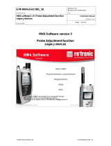
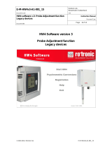
The following diagram shows the function blocks:
Figure 1: Overview of the function blocks of the CRP5 clean room panel

E-M-CRP5-V1_02_EN.docx
Rotronic AG
Bassersdorf, Switzerland
Document Code
Unit
CRP5 Clean Room Panel
Instruction Manual
Instruction Manual
Document Type
Page
6 of 39
Document Title
© 2018; Rotronic AG E-M-CRP5-V1_02_EN.docx
Technical Drawings
The CRP5 clean room panel is intended for mounting in walls or switch cabinet doors. The external dimensions
are shown in the following drawings.
Figure 2: CRP5 dimensional drawings
with HC2-CRP front panel probe (left) and E2 connection for external HC2 probe (right)
HC2-CRP
HC2-CRP-HOLDER
Figure 3: HC2-CRP dimensional drawing
Figure 4: HC2-CRP-Holder dimensional drawing

E-M-CRP5-V1_02_EN.docx
Rotronic AG
Bassersdorf, Switzerland
Document Code
Unit
CRP5 Clean Room Panel
Instruction Manual
Instruction Manual
Document Type
Page
7 of 39
Document Title
© 2018; Rotronic AG E-M-CRP5-V1_02_EN.docx
2 General Description
Connections
Front: The CRP5 is equipped with a combined probe (HC2-CRP) for relative humidity and temperature in a
stainless steel housing that is fastened to the front panel without risk of mix-up with a magnetic holder. The
probe is connected to the CRP5 electronics by four stainless steel spring pins. The HC2-CRP probe sends its
measured values to the CRP5 electronic evaluation unit in digital form.
Two stainless steel pressure connections labelled + and – on the right and
left of the HC2-CRP probe permit calibration and adjustment of the device
from the clean room. When not in use, they are closed with two stainless steel
screw caps.
The CRP5 can optionally also be ordered without the front-side HC2-CRP combined probe. In this alternative
there is a 7-pin connection socket at the back of the device for remote connection of a standard HC2 sensor
(HygroClip 2) via a connection cable (e.g. probe extension cable E2-01A). The measured values are transmitted
in digital and analog form.
Figure 5: Rear view of the
combined probe HC2-CRP
with spring contact pins
Figure 6: Front view of the
CRP5 with front-side HC2-CRP
probe
Figure 7: Front view of CRP5 for remote HC2 probe
Figure 6: Connections at the rear

E-M-CRP5-V1_02_EN.docx
Rotronic AG
Bassersdorf, Switzerland
Document Code
Unit
CRP5 Clean Room Panel
Instruction Manual
Instruction Manual
Document Type
Page
8 of 39
Document Title
© 2018; Rotronic AG E-M-CRP5-V1_02_EN.docx
Rear: A 36-pole connector strip
with screw terminal blocks is used
for rear connection of the CRP5.
Their assignment is shown in the
figure opposite. The rear of the
device also has an RJ45 Ethernet
socket for LAN integration, a Mini-
USB service port (UART) for
connection to a Windows
PC/laptop running the
ROTRONIC HW4 software via an
optional AC3006 service cable,
two pressure connection nipples
and optionally a 7-pin connection
socket for an external
ROTRONIC HC2 HygroClip
humidity and temperature sensor.
Attention!
Regarding the grounding, all terminals marked with a minus sign (-) are connected commonly, this includes
the power supply and the protective ground. Only the relay outputs and data connections are isolated.
Figure 7: Assignment of the CRP5’s rear terminal strip

E-M-CRP5-V1_02_EN.docx
Rotronic AG
Bassersdorf, Switzerland
Document Code
Unit
CRP5 Clean Room Panel
Instruction Manual
Instruction Manual
Document Type
Page
9 of 39
Document Title
© 2018; Rotronic AG E-M-CRP5-V1_02_EN.docx
Power Supply / Current Consumption
The power supply for the CRP is connected via the screw contacts 2/3 (V-) and 4/5 (V+). Screw contact 1 is
used to connect protective earth. The screw terminals are implemented in twos so that the supply voltage can
be looped through to a further load should this be necessary.
Note:
The device does not have galvanic isolation.
The power supply is equipped with polarity protection.
Differential Pressure Measurement
The calibrated and thermally compensated differential pressure sensors used by ROTRONIC guarantee an
exact and stable output signal over a wide temperature range.
The piezoresistive diaphragm sensor is based on the principle of MEMS. This guarantees high immunity to dust
and avoidance of cross contamination between the two spaces in which the pressure is measured.
Measurement Ranges
The following sensor measurement ranges are available:
-50 … +50 Pa
-100 … +100 Pa
-250 … +250 Pa
-500 … +500 Pa
Operating Voltage
Current
Consumption
20 … 48 VDC
<500 mA
18 … 35 VAC / 50/60 Hz
<500 mA
Figure 9: CRP5 connections with HC2-CRP
Figure 8: CRP5 connections with external HC2
probe

E-M-CRP5-V1_02_EN.docx
Rotronic AG
Bassersdorf, Switzerland
Document Code
Unit
CRP5 Clean Room Panel
Instruction Manual
Instruction Manual
Document Type
Page
10 of 39
Document Title
© 2018; Rotronic AG E-M-CRP5-V1_02_EN.docx
Units
The following units are available for differential pressure: pascal (Pa), inch water column (inH
2
O), pound per
square inch (psi), millibar (mbar), mm mercury column (mmHg), mm water column (mmH
2
O), torr (Torr), gram
per square centimetre (g/cm²). The following table shows the conversion factors between the different units.
Figure 10: Conversion of common pressure units
Smoothing Filter
The differential pressure measured value curve can be smoothened by forming a moving average (MA) over
the latest measurements. Up to 10 measurements can be incorporated in the average value (greatest
smoothing); the default setting is five measurements.
The current measured value is added up with the previous N-1 measured values and divided by N. When there
is a new measured value, the oldest value in the measured value set is dropped from the calculation and the
new measured value is added.
Simulation Value
When the simulation value has been activated, a defined simulation value is used instead of the current
measured value. This makes it possible to test whether the CRP5 transmits a defined fictitious measured value
to the monitoring system correctly to verify error-free communication.

E-M-CRP5-V1_02_EN.docx
Rotronic AG
Bassersdorf, Switzerland
Document Code
Unit
CRP5 Clean Room Panel
Instruction Manual
Instruction Manual
Document Type
Page
11 of 39
Document Title
© 2018; Rotronic AG E-M-CRP5-V1_02_EN.docx
HC2-CRP and HC2 Connection
In the standard version of the device the HC2-CRP probe is connected on the front panel via a magnetic holder.
The CRP5 can optionally be delivered with an alternative E2 connection socket at the rear for connection of a
remote HC2 probe via a connection cable.
Units
The following units are available for the HC2-CRP and external HC2 connection:
% RH
°C / °F
Simulation Value
When the simulation value has been activated, a defined simulation value is used instead of the current
measured value. This makes it possible to test correct transmission of measured values.
Analog Inputs
The two analog inputs 33/34 (IN1-/IN1+) and 35/36 (IN2-/IN2+) can be switched between voltage and current
measurements. The respective input signals may not exceed a maximum signal amplitude of 0 … 3.3 V (internal
resistance >100 k) or 0 … 25 mA (measuring resistance 120 , 0.1%) and are quantized with 15 bit.
Information!
The 120 Ohm burden for a current input is programmatically inserted and the user does not need to supply
an external resistor.
Ambient Pressure
The ambient pressure sensor used features a short response time and high resolution. Its extreme long-term
stability, combined with remarkable pressure resistance, guarantees years of precise and maintenance-free
operation and exact psychrometric calculations.
Ambient Pressure Sensor
Absolute accuracy
±1 hPa (0 … 65 °C; 950 … 1100 hPa) max.
Relative accuracy
0.12 hPa (25 °C; 950 … 1050 hPa) typ.
Temperature coefficient offset
1.5 Pa/K (+25 … 40 °C @ 900 hPa)
Working range - pressure
300 … 1100 hPa
Working range - temperature
0 … 65 °C
1.

E-M-CRP5-V1_02_EN.docx
Rotronic AG
Bassersdorf, Switzerland
Document Code
Unit
CRP5 Clean Room Panel
Instruction Manual
Instruction Manual
Document Type
Page
12 of 39
Document Title
© 2018; Rotronic AG E-M-CRP5-V1_02_EN.docx
Analog Outputs
The ROTRONIC HW4 software enables free configuration and scaling of the four analog outputs 25/26 (OUT1-
/OUT1+), 27/28 (OUT2-/OUT2+), 29/30 (OUT3-/OUT3+) and 31/32 (OUT4-/OUT4+). The measured values
Differential Pressure, Relative Humidity, Temperature and Calculated Value and the input signals Analog Input
1, Analog Input 2, Digital Input 1 and Digital Input 2 can be assigned to any analog output and scaled at will.
The following output ranges are available:
Signal Type
Range
Maximum Offset at Start of Range
Voltage
0 … 1 V
0 … 5 V
0 … 10 V
3 mV
50 mV
90 mV
Current
0 … 20 mA
4 … 20 mA
4 µA
No offset
Scaling of the Measured Parameters
The scale can be changed at will with the ROTRONIC HW4 software in a range from -9,999 to +99,999. The
limits of the sensor must, however, be observed.
The devices have one of the following optional default settings on delivery.
Analog Outputs
Operating Range of the
Differential Pressure
Sensor
Limit Values of the Differential Pressure Sensor
0 … 10 V
or
4 … 20 mA
-50 …+ 50 Pa
-60 … +60 Pa
0 … +50 Pa
-60 … +60 Pa
-100 … +100 Pa
-120 … +120 Pa
0 … +100 Pa
-120 … +120 Pa
-250 … +250 Pa
-300 … +300 Pa
0 … +250 Pa
-300 … +300 Pa
-500 … +500 Pa
-600 … +600 Pa
0 … +500 Pa
-600 … +600 Pa
Digital Inputs
There are two digital inputs 21/22 (D-IN1-/D-IN1+) and 23/24 (D-IN2-/D-IN2+) available for logic signals with a
maximum voltage range from 0 ... 24 VDC. The input resistance is 10 k input voltages <1.5 V are interpreted
as logic “0” and >3.5 V as logic “1”.
Digital Inputs
Input voltage
0 … 24 VDC
Input resistance
10 k

E-M-CRP5-V1_02_EN.docx
Rotronic AG
Bassersdorf, Switzerland
Document Code
Unit
CRP5 Clean Room Panel
Instruction Manual
Instruction Manual
Document Type
Page
13 of 39
Document Title
© 2018; Rotronic AG E-M-CRP5-V1_02_EN.docx
Switching threshold
>3.5 VDC (high, logic 1), <1.5 VDC (low, logic 0)
Relays
The CRP5 provides six volt-free semiconductor relays (NO: normally open): 6/7 (REL1-/REL1+), 8/9 (REL2-
/REL2+), 10/11 (REL3-/REL3+), 12/13 (REL4-/REL4+), 14/15 (REL5-/REL5+), 16/17 (REL6-/REL6+).
The relays can be controlled via freely configurable low/high alarms by the parameters Differential Pressure,
Relative Humidity, Temperature, Calculated Parameters and the two analog and digital inputs. The following
can also be set:
Time delay
The relay is only switched on when an alarm endures for a certain minimum time.
Switch off when alarm finished
The relay automatically disengages when the alarm is no longer active; otherwise the relay remains
active until it is reset manually.
Maximum duty cycle
The relay stays on for at most the time set and is then switched off.
Only one measured value can be used to activate a relay. Assignment of more than one measured value is not
possible.
Relay Characteristics
Number of relays
6
Type of relays
FET (solid state relay)
Switching capacity
DC voltage: 100 W (50 VDC @ 2 A), observe polarity
AC voltage: 50 W (50 VAC (peak) @ 1 A), polarity arbitrary
Digital Interface – Modbus RTU
See separate manual D-M-CRP5-MODBUS.
Service Interface
A computer running the ROTRONIC HW4 software can be connected via the service interface (Mini-USB at the
rear of the device, UART) using an AC3006 connection cable. It can then be used to make device settings, load
language data and update the firmware.
Important:
The CRP5 can be supplied with power via the AC3006 service cable. However, the valves for zeroing and
calibration as well as the analog outputs are not active in this case.
For sensor adjustment, the CRP5 must be supplied with power from a suitable power source.

E-M-CRP5-V1_02_EN.docx
Rotronic AG
Bassersdorf, Switzerland
Document Code
Unit
CRP5 Clean Room Panel
Instruction Manual
Instruction Manual
Document Type
Page
14 of 39
Document Title
© 2018; Rotronic AG E-M-CRP5-V1_02_EN.docx
Display and Keys
The colours for the background and measured
values in normal and alarm cases are freely
selectable. There are six display lines available as
follows:
Line 1 … 3: Differential pressure (Pa), relative
humidity (%RH), temperature (°C)
Line 4: Analog input values (IN1, IN2),
calculated values (all psychrometric
calculations), no value
Line 5 … 6: Ambient pressure (hPa),
digital input values (D-IN1, D-IN2), no value
Example: The first line of the display shows the
differential pressure, the second the relative
humidity, the third the temperature and the fourth
the calculated value for dew point. Arrows at the
beginning of every line indicate the measured value trend:
falling, rising, constant.
Line 5 is configured for the ambient pressure and line 6 for the logic level at digital input D-IN2.
Key Symbols:
MENU
Down (decrease value)
Up (increase value)
Enter (finish entry)
Note:
Unauthorized use of the menu via the keys on the front panel can be prevented with the ROTRONIC HW4
software: Device Manager > Settings > Key Lock. After entering an own password and confirming it with OK,
the message “Menu blocked” appears in the display of the CRP5 when pressing the menu key and further
pressing of keys has no effect.
Alarms
The display colour of measured values in an alarm state changes to a preselectable colour (e.g. red). Alarms
are configured with the ROTRONIC HW4 software.
Figure 11: Operating keys and display in the CRP front
panel

E-M-CRP5-V1_02_EN.docx
Rotronic AG
Bassersdorf, Switzerland
Document Code
Unit
CRP5 Clean Room Panel
Instruction Manual
Instruction Manual
Document Type
Page
15 of 39
Document Title
© 2018; Rotronic AG E-M-CRP5-V1_02_EN.docx
Decimals
Depending on the size of the measured value, measured values are shown in the CRP5 display with one or two
decimals.
HW4 Software Compatibility
The CRP5 clean room panel is fully integrated in the ROTRONIC HW4 software from Version 3.6 and later.

E-M-CRP5-V1_02_EN.docx
Rotronic AG
Bassersdorf, Switzerland
Document Code
Unit
CRP5 Clean Room Panel
Instruction Manual
Instruction Manual
Document Type
Page
16 of 39
Document Title
© 2018; Rotronic AG E-M-CRP5-V1_02_EN.docx
3 Mechanical Installation
General
The CRP5 can be flush-mounted in a wall. The position of the device has no influence on measurement. For
exact measurements, the CRP5 must not be exposed to vibrations.
Installation in the Wall
Cut a suitable opening and drill holes according to the technical drawing.
CAUTION! It is advisable not to use metal screws to prevent glass breakage due to excessive
mechanical stresses.
Recommended accessories:
4 x M4x16 PEEK plastic countersunk screws with cross-head (polyetheretherketone,
AC6102)
Mounting holder (AC6101)
Differential Pressure Connection
Tubes with an internal diameter of 4 mm can be connected at the rear (front: 6 mm). The tubes must be
fastened securely so that they do not move or vibrate during operation. This would falsify the measurement.
Marking of the differential pressure connections:
+ Positive pressure connection
– Negative pressure connection
Figure 14: Differential pressure connections at the rear
Figure 13: Mounting holder AC6101
Figure 12: PEEK
screws AC6102

E-M-CRP5-V1_02_EN.docx
Rotronic AG
Bassersdorf, Switzerland
Document Code
Unit
CRP5 Clean Room Panel
Instruction Manual
Instruction Manual
Document Type
Page
17 of 39
Document Title
© 2018; Rotronic AG E-M-CRP5-V1_02_EN.docx
HC2-CRP Connection
The combined HC2-CRP humidity and temperature probe is connected at the front of the CRP5. It is fastened
firmly and without risk of mix-ups on its holder by integrated magnets, and bonded to the electronics of the CRP5
by spring contact pins.
Figure 16: HC2-CRP connection
Figure 15: HC2-CRP-HOLDER connection
Figure 17: HC2-CRP rear
Figure 18: HC2-CRP-HOLDER rear

E-M-CRP5-V1_02_EN.docx
Rotronic AG
Bassersdorf, Switzerland
Document Code
Unit
CRP5 Clean Room Panel
Instruction Manual
Instruction Manual
Document Type
Page
18 of 39
Document Title
© 2018; Rotronic AG E-M-CRP5-V1_02_EN.docx
HC2 Connection
Instead of a front-side HC2-CRP connection, the CRP5 can alternatively be ordered with an E2 socket at the
rear for an external HC2 probe. This interface and its possible uses are described below.
Use with HC2 Probe
After connecting a remote HC2 probe to the rear E2 socket via an extension cable, it is possible to make the
same measurements as with a HC2-CRP probe on the front panel: relative humidity and temperature. The digital
measured data of the HC2 probe is evaluated by the CRP5.
Figure 19: Connection socket for an external HC2 probe
Pin Configuration E2 Connection (view from front)
The pins 5 to 7 are not used in the CRP5.
1) V+: Digital probe: 3.3 VDC, 10 mA (+)
2) GND: Digital and supply ground (-)
3) RXD: UART digital probe (receive)
4) TXD: UART digital probe (transmit)
5) ANA IN: Analog input: 0…3.2 V / 0…25 mA
6) NU: Not used
7) AGND: (Analog GND)
Figure 17: Pinout E2
connection for
external HC2 probe
Figure 20: Pinout E2
connection for
external HC2 probe

E-M-CRP5-V1_02_EN.docx
Rotronic AG
Bassersdorf, Switzerland
Document Code
Unit
CRP5 Clean Room Panel
Instruction Manual
Instruction Manual
Document Type
Page
19 of 39
Document Title
© 2018; Rotronic AG E-M-CRP5-V1_02_EN.docx
4 Information on Use
Signal Cables
The following guidelines are derived from the European standard EN 50170 for the transmission of signals by
copper wires. Note on installation planning: when determining the position of machinery and equipment, the
rules given in EN 50170 should be followed with due regard to local circumstances.
The CRP5 is tested for electromagnetic compatibility according to the EMC Directive 2004/108/EC and the
following European standards:
- EN 61000-6-1: 2007, EN 61000-6-2: 2005, EN61326-1:2013
- EN 61000-6-3: 2007+A1:2011+AC:2012, EN 61000-6-4: 2007+A1:2011
Whenever the level of electromagnetic interference is expected to be high, both the devices and signal cables
should be placed as far away as possible from the source of interference.
In general, signal cables should be installed in bundles or channels / conduits, separate from other cables as
indicated in the table below:
Bus signals such as RS-485
Data signals for PCs, printers, etc.
Shielded analog inputs
Unshielded DC voltage (<= 60 V)
Shielded process signals (<= 25 V)
Unshielded AC voltage (<= 25 V)
Coaxial cables for CRT monitors
in common bundles or channels / conduits
DC voltage from 60 V to 400 V (unshielded)
AC voltage from 25 V to 400 V (unshielded)
in separated bundles or channels / conduits,
without minimum distance
DC and AC voltage > 400 V (unshielded)
Telephone lines
Lines leading into EX-rated areas
in separated bundles or channels / conduits,
without minimum distance

E-M-CRP5-V1_02_EN.docx
Rotronic AG
Bassersdorf, Switzerland
Document Code
Unit
CRP5 Clean Room Panel
Instruction Manual
Instruction Manual
Document Type
Page
20 of 39
Document Title
© 2018; Rotronic AG E-M-CRP5-V1_02_EN.docx
Differential Pressure Measurement
Influence of the Ambient Pressure
The measuring accuracy of the integrated differential pressure sensor is not dependent on the local absolute
ambient air pressure.
Influence of Dust, Temperature and Humidity
Since the differential pressure sensor evaluates the air pressure difference between its two inputs without air
flowing through it, dust particles do not enter the inlet tubes and reach the sensor. The device is thus largely
insensitive to dust in the air being measured.
Units
The default analog input unit is mV / mA. A user-specific unit can be configured in the ROTRONIC HW4 software
(e.g. %, mbar, etc.). There is a maximum of four characters available for this. If three pre-decimal positions are
relevant, the decimal is rounded to one digit.
Scaling of the Analog Inputs
The CRP5 has two analog inputs (IN1+ / IN1-, IN2+ / In2-).
The analog inputs can be switched between voltage and current measurement by Rotronic-HW4-Software or
Modbus protocol.
For voltage measurement, the signal range is from 0 to 3'300 [mV]. Internal resistance is greater than 100 [kΩ].
A resistance of 120 [Ω] is used for the current measurement. This results in a signal range of 0 to 27 [mA].
Attention!
The 120 Ohm burden for a current input is programmatically inserted and the user does not need to supply
an external resistor.
Scaling of the analog input
The analog input is freely scalable via the Rotronic-HW4-Software or the Modbus protocol.
Note
Input range for voltage measurement: 0 to 3300 [mV] (by steps of 1 [mV]
Input range for current measurement: 0 to 27 [mA] (by steps of 1 [mA]
Negative voltages and currents cannot be measured
Output range (e.g. display): -9'999 to 32767
The measuring ranges for voltage and current are secured, but should only be exceeded for very short
periods
Calculation of the display value
The display value is calculated from the settings of the input (Input Range) and processing range (Processing
Range).
/