Page is loading ...

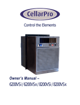
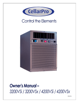
SC SERIES
OWNER’S MANUAL
SC PRO 2000
SC PRO 3000
SC PRO 4000
SC PRO 8000

Copyright © 2020. WhisperKOOL. All rights reserved.
WhisperKOOL copyrights this manual, the product design, and the design concepts, with all rights reserved. Your rights with
regard to the hardware and manual are subject to the restrictions and limitations imposed by the copyright laws of the USA.
Under copyright laws, this manual may not be copied, reproduced, translated, transmitted, or reduced to any printed or electronic
medium or to any machine-readable form, for any purpose, in whole or in part, without the written consent of WhisperKOOL.
Every eort has been made to ensure that the information in this manual is accurate. WhisperKOOL is not responsible for printing
or clerical errors.
WhisperKOOL reserves the right to make corrections or improvements to the information provided and to the related hardware at
any time, without notice.
Vinothèque and WhisperKOOL are registered trademarks, and ECE is a trademark of WhisperKOOL. All rights reserved.
Mention of third-party products is for informational purposes only and constitutes neither an endorsement nor a recommendation.
WhisperKOOL assumes no liability with regard to the performance or use of these products.
We manufacture, test and certify 100% of our wine cooling units in
the USA. By sourcing the best components and closely controlling our
manufacturing processes, we can assure the highest-quality,
lowest defect manufacturing rates in the industry.
Conforms to ANSI/UL Std 427
Certied to CAN/CSA Std C22.2 No. 120

TABLE OF CONTENTS
Introduction ............................................................. 2
Before You Start .........................................................3
Receiving and Inspecting the Unit .......................................4
Quick Reference Guide ..................................................5
Controller Layout ............................................................6
Unit Specications ..........................................................6
Preparing the Wine Cellar ...............................................7
Pre-Installation ..........................................................10
Testing the Unit prior to Installation ..........................................10
Installation Guide .......................................................11
Preparing the Installation Location .......................................11
Preparing the Unit for Installation ........................................ 12
Installing the Unit through the Wall ......................................13
Condensation Drain Line ................................................14
Liquid Measuring Thermostat System ...................................15
System Operation .......................................................15
Controller ...............................................................17
Functions .............................................................17
Alarm Codes ..........................................................18
CPSM (Customer Preference Selection Mode) .............................18
Wiring Schematic ........................................................ 19
Troubleshooting Guide ..................................................23
Maintenance Schedule ..................................................25
Technical Assistance & Accessories ......................................26
Installation Terms & Conditions .......................................... 27

SC 010920
Page 2 | 1-800-343-9463
INTRODUCTION
Customer Service
Thank you for purchasing a WhisperKOOL cooling system. We strive to provide the highest-quality products and the best possible
customer service. If you have any questions about your system, please call us at 1-800-343-9463 or visit whisperkool.com.
Using the Manual
This manual is intended to assist in the proper maintenance of the cooling system. In order to ensure the longevity of your
cooling unit, the equipment should be installed correctly and have a proper care and maintenance schedule. Please read and
review this manual carefully and keep it for future reference.
What is the WhisperKOOL Cooling Unit?
The WhisperKOOL cooling unit is a specialized refrigeration unit designed for one purpose only: to maintain the optimal
temperature and humidity levels conducive to the proper storage and aging of ne wines. It is a self-contained cooling unit
designed to be used as a forced-air through-the-wall unit.
How Does the WhisperKOOL Cooling Unit Work?
The WhisperKOOL cooling unit is specially designed for the use and application to maintain optimal conditions for wine storage
and aging. The unit is fully self-contained and is designed to be installed as a through-the-wall application with the ability to duct
the exhaust air. The unit is temperature-controlled via a bottle probe.
Temperature Setting
The system is designed to maintain a cellar temperature of 55°F as long as the ambient temperature does not exceed 85°F.

www.whisperkool.com | Page 3
SC PROSeries
BEFORE YOU START
This guide is meant to serve as a quick reference for installation of the WhisperKOOL unit. The remainder of this owner’s manual
will provide more detailed information and instructions.
Upon receiving the WhisperKOOL cooling unit:
1. Inspect the unit before installation. If damage is found, please contact your distributor or WhisperKOOL Customer Service
at 1-800-343-9463.
2. The unit should remain in an upright position for 24 hours prior to operation.
3. The WhisperKOOL SC PRO 2000, SC PRO 3000, and SC PRO 4000 units require a dedicated 115-volt, 15-amp circuit.
The WhisperKOOL SC PRO 8000 unit requires a dedicated 115-volt, 20-amp circuit. Use a surge protector with the
WhisperKOOL units. Do not use a GFI (ground fault interrupter) line. GFI’s are too sensitive to be used with WhisperKOOL
units, they will trip prematurely and prevent the unit from operating.
4. For your convenience, the WhisperKOOL unit has two power inlets: one on the side of the unit, and the other on the back.
Use the selector switch, located on the right side of the unit, to select the inlet you would like to use.
5. The unit is designed to gently cool down the temperature of the cellar over time by cycling cooler air throughout.
Test the unit prior to installation.
6. You are required to install a drain line to remove condensation from the unit.
7. The WhisperKOOL unit is intended for use in properly designed and constructed wine cellars. Hire a professional wine
storage consultant with a valid contractor’s license to build your wine cellar.
Never try to open the WhisperKOOL unit, repair it yourself, or use a service company
without WhisperKOOL’s authorization. This will void your warranty.
If you encounter a problem with your WhisperKOOL unit, please refer to the Troubleshooting Guide. If you have any further
questions or concerns, or need assistance, please contact WhisperKOOL Customer Service at 1-800-343-9463. Please be sure all
testing has been completed prior to contacting Customer Service. Please have your results ready for your representative.
Please review the installation instructions in this manual. Failure to follow proper installation
procedures will void your warranty.

SC 010920
Page 4 | 1-800-343-9463
NOTE: WhisperKOOL units are manufactured in the USA and tested prior to shipment.
Please leave the WhisperKOOL unit in its original box until you are ready for installation. If the unit is to be stored for any length
of time prior to installation, ensure that the unit is stored on a at level surface in the upright position. This will allow you to
move the product safely without damaging it. When you are ready to remove the product from the box, refer to the installation
instructions.
TIP: Save your box and all packaging materials. They provide the only safe means of transporting/shipping the unit.
2000 / 3000 / 4000 / 8000
Single-piece mounting bracket
Accessory kit #1:
• (1) WhisperKOOL SC Series owner’s manual
• (1) Bypass plug
• (1) Liquid-measuring thermostat (bottle probe)
Accessory kit #2:
• (1) Power cord (8 feet)
• (1) Piece of mounting bracket insulation foam (6 feet)
• (11) 1¾" standard screws
• (7) ½" Phillips pan-head screws
• (1) Drain line tube (½" ID clear plastic tubing, 10 feet)
• (1) ¼" FNPT x ½" Hose elbow
RECEIVING AND INSPECTING THE UNIT
Upon receiving your WhisperKOOL unit:
• Lift only at the designated hand-hold locations on the shipping container, or fully support the unit from underneath.
A shipment may include one or more boxes containing accessories.
• Inspect the packaging for any obvious signs of damage or mishandling before opening the container.
• Place the box containing the WhisperKOOL unit on a tabletop to prepare it for testing prior to installation.
• Review the packing slip to verify the package’s contents.
• Check the model number to ensure it is correct.
• Check that all factory options ordered are listed.
• Check the box for the following:

www.whisperkool.com | Page 5
SC PROSeries
QUICK REFERENCE GUIDE
Front / Side View
Rear / Side View
Controller
Bottle probe
Probe input
Control panel
(see page 10 for details)
Drain port
Rear power inlet

SC 010920
Page 6 | 1-800-343-9463
Compressor is On
Unit is in Anti-Frost Mode
Fans are On
Alarm is present
Temperature Measurement
CONTROLLER LAYOUT
Refer to page 18 for complete listing of buttons and symbols.
UNIT SPECIFICATIONS
2000 3000 4000 8000
Dimensions 17.5"L x 14.25"W x 15.75"H 21.64"L x 14.25"W x 22.56"H
Refrigerant R-134a
HP 1/8 1/6 1/6+ 1/2
Voltage Rating 115V (15-amp (2000/3000/4000) or 20-amp (8000) dedicated circuit required)
Weight (lbs) 60 60 60 104
Amps (running) 3.2 3.7 4.7 10.9
Drain Line ½" ID clear plastic tubing
Installation Through the wall
Thermostat Advanced digital controller, liquid-temperature-measuring bottle probe
Temp. Delta Can maintain a 55°F cellar temperature with up to 85°F condenser air intake temperature
Outside Venting Not recommended
Warranty Two-year limited warranty (parts and labor) / Five-year limited warranty (compressor)
Menu Navigation
and Value Increase
(Press and hold to manually
enter Anti-Frost mode.)
Power On/O
(hold for approx. 3 seconds)
and Escape
Menu Navigation
and Value Decrease
SET (ENTER)
(Press and hold
to enter the
parameter menu.)
* See note on next page
Contact our sales team if your cellar incorporates stone, concrete, or glass in its construction.

www.whisperkool.com | Page 7
SC PROSeries
* Sizing the Unit to the Room
The specication chart will provide information on the unit's cooling capacity. There are circumstances in which a cellar design may
require a larger unit due to preexisting design restrictions. Certain building materials such as glass, stone, or concrete may seem
adequate but do not oer the insulation capacity required to maintain the optimum temperature for storing wine. We recommend
purchasing a unit with a larger capacity to compensate for these design limitations. Undersized cooling units can lead to premature
failure and/or prevent the system from reaching the desired set temperature. As a result, they are not covered under warranty.
The performance and life of your system is contingent upon the steps you take in preparing the wine cellar. Improp-
erly preparing your enclosure or incorrectly installing your unit may cause unit failure, leaking of condensation, and
other negative side eects.
It is highly recommended that you obtain the assistance of a wine storage professional.
Wine storage professionals work with licensed contractors, refrigeration technicians, and racking companies to build
well-insulated, beautiful, and protective wine cellars. WhisperKOOL has put together some useful tips to assist in the
installation process. Our recommendations are meant to act as a guide in the process of building a proper enclosure.
Your intended location may have specic needs which we do not address.
Wall & Ceiling Framing
Build wine cellar walls using standard 2x4 or 2x6 boards and ceiling joists without violating local or state codes in
your area. As a general rule, the thicker the walls and the higher the insulation value, the more consistent your cellar
temperature will be.
Insulation
Insulation is REQUIRED in order to properly use WhisperKOOL products. It is vital that all walls and ceilings be
insulated to keep the cellar temperature as consistent as possible during the summer and winter months. Standard
berglass or rigid foam insulation is normally used in cellar construction; in some cases, “blown-in” insulation is used.
The R-value, or quality of insulation, is determined by the rate at which heat passes through the insulation. The
higher the R-value, the more resistant the insulation is to conducting heat, and the more consistent your wine cellar’s
temperature will be. Using higher R-values in insulation will lower your operating costs and WhisperKOOL unit run
time. (R-13 is the recommended minimum; R-19 is preferred for interior cellar walls, and R-30 for ceilings and exterior
walls.)
Vapor Barrier
Water vapor creates its own pressure, separate from the ambient air pressure, and will intrude into colder/drier
areas. A vapor barrier is REQUIRED in order to prevent the intrusion of water vapor and maintain the correct cellar
temperature and humidity. It is recommended that 6-millimeter plastic sheeting be applied to the warm side of the
cellar walls. The vapor barrier must also be applied to the outside walls and ceiling. If it is impossible to reach the
outside, then the plastic must be applied from within the cellar. The most common method is to wrap the entire
interior, leaving the plastic loose in the stud cavity so the insulation can be placed between each stud. All of the walls
and ceiling must be wrapped in plastic for a complete vapor barrier.
In areas of high humidity, such as Southern and Gulf States, the vapor barrier will prevent inltration of warm moist
air. The moist air can cause mold to form, and standing water in drain pans promote microbial and fungal growth that
cause unpleasant odors and indoor air quality problems. If mold is found, remove it immediately and sanitize that
portion of the unit.
Note: High humidity signicantly increases the heat load on the cooling system.
Any break in the vapor barriers (cut, nail hole, over-lapping, etc.) will cause a moisture leak and must be sealed. The
electric conduit is a “duct” for vapor to travel in. The conduit should be caulked and sealed on the warm air end.
PREPARING THE WINE CELLAR

SC 010920
Page 8 | 1-800-343-9463
Mounting the Unit
The unit must be mounted within 18 inches of the ceiling in order to achieve sucient cooling. As the room cools down, the
warm air will rise to the ceiling. Mounting the unit high in the room will create a consistently cool environment by capturing the
warm air and replacing it with cool air. Mounting the unit low in the room will result in a temperature variation in the room due
to (a) the unit’s inability to draw warm air down from the ceiling and (b) cold air settling to the oor.
Door and Door Seal
An exterior-grade (1¾”) door must be installed as a cellar door.
It is very important that weather stripping be attached to all
four sides of the doorjamb. A bottom “sweep” or threshold is
also required. The door must have a very good seal to keep
the cool cellar air from escaping out of the cellar. If the cellar
door does not seal properly, the unit will run continuously.
In cases where glass doors are used and the room size is
close to the recommended unit size, the next larger size
WhisperKOOL should be used. This will compensate for the
insulation loss due to the lower insulation rating of glass.
Wine Cellar
Exhaust Area
Keep Clear
Exhaust Fan/Vent
(optional)
Air Intake
(optional)
Unobstructed Airow
Unobstructed airow to and from the unit is critical for the unit’s overall performance and lifespan. Make sure there is a
minimum of three (3) feet of horizontal clearance in every direction around the unit (ve feet is ideal). The air blown by the fans
needs to circulate and either dissipate or absorb heat from the space. The system will operate more eciently with a greater
amount of air to exchange.
NOTE: Do not attempt to mount the unit in a wall recess or attempt to camouage or cover the unit with any sort of aftermarket
grille, accessory, etc. This can restrict airow, prevent the unit from working properly, and void the warranty. Please feel free to
call WhisperKOOL Customer Service with any questions or concerns regarding installation requirements.

www.whisperkool.com | Page 9
SC PROSeries
Ambient Temperature Factor
The cooling unit has the ability to cool a wine cellar eciently to 55°F as long as the intake air does not exceed 85°F. Therefore,
you want to exhaust the unit in a room which will not exceed 85°F. Without proper heat dissipation the unit will not have the
capacity to keep the wine at a desirable 55°F.
Exhaust Fan
Air Intake Cellar Wall
85
º
F 55
º
F
WhisperKOOL
(side view)
Back — Exhaust Room Front — Wine Cellar
Ventilation
The necessity of dissipating heat away from the unit is critical to the unit’s performance and cannot be overstated. As the unit
operates and cools, a greater amount of heat is generated on the exhaust side of the unit. Adequate ventilation is required in
order to dissipate heat away from the unit. If ventilation is inadequate, the exhaust will heat the area or room and adversely aect
the unit’s ability to cool. In some cases, it may be advisable to install a vent fan to dissipate heat from within the exhaust area.
However, you must have a fresh air inlet as well. If your unit requires ducting, please contact WhisperKOOL to obtain a specially
designed ducting plenum for the unit.
Using any other ducting system will void the warranty.
NOTE: If you are unsure whether you have adequate ventilation in your install location, please
contact us to assess your specic installation at suppor[email protected] or 1-800-343-9463.
WARNING! Allowing your unit to operate in high ambient temperatures for extended
periods of time will greatly decrease the life of your unit and void your warranty.

SC 010920
Page 10 | 1-800-343-9463
PREPARING THE UNIT FOR INSTALLATION
The WhisperKOOL 2000, 3000, and 4000 unit requires a dedicated 115-volt, 15-amp circuit. The 8000 unit requires a
dedicated 115-volt, 20-amp circuit The unit draws a large amount of amps during its initial startup. By designating a dedicated
circuit breaker, you will guarantee the unit has enough power to run eectively. Contact an electrician for assistance with the
installation of this dedicated electrical circuit.
The unit must sit upright for 24 hours prior to testing and installation. To prepare the unit for testing:
• Remove unit from box
• Place unit on tabletop
• Plug in unit to electrical outlet
• Plug in bottle probe
• Turn on to test for approximately 20–30 minutes
• Turn o after test
• Disconnect bottle probe
To prepare the unit for installation:
• Match the electrical outlet to the plug provided on the WhisperKOOL unit.
• Provide a dedicated circuit and wiring for the unit.
• Provide a weatherproof plug for units connected outside.
Power surges and spikes can damage sensitive electrical equipment. WhisperKOOL recommends plugging the unit into a surge
protector or power conditioner in order to protect your system. As outlined in our terms and conditions, power surges and spikes
are not covered under warranty.
We recommend that you do not use a GFI (ground fault interrupter) with this product.
Electrical Inlets
The unit is equipped with two power inlets. One is located on the right side of the unit (inside of the cellar), and the other is
located on the rear of the unit (outside of the cellar). Use the selector switch located on the right side of the unit to select which
power inlet you would like to use. If you would like to plug the unit into a socket outside of the cellar, set the selector switch to
rear. If you would like to plug the unit into a socket inside of the cellar, set the selector switch to the front position. When placed
in either position, power can only enter the unit utilizing the power inlet you’ve selected.
In case the unit should lose power, check the home/main circuit breaker. If the unit does not respond properly, refer to the
Troubleshooting Guide.
FRONT
REAR
Power Inlet
Front/Rear
Power Switch

www.whisperkool.com | Page 11
SC PROSeries
Locate the desired installation location (no lower than 18 inches from the ceiling).
Using a stud nder, locate the studs on either side of the center point, and mark them
with vertical lines.
Using a level and a pencil, mark a horizontal line on the wall between the two studs,
no less than 1.5 inches and no more than 18 inches from the ceiling.
Using a ruler or measuring tape, measure 16 inches down (2000/3000/4000) or 22.75
inches down (8000)and mark another horizontal line parallel to the rst one. The unit
is designed to t between two studs that are 16 inches apart on center, enabling the
unit to t in the 14.5-inch horizontal space.
Using a saw, cut along the uppermost horizontal line until your saw reaches the stud.
Turn the saw around, inserting it into the cut that has just been made, and cut toward
the opposite stud so that there is a clean horizontal cut between the two studs. Be
careful not to cut into the studs themselves.
Make the second horizontal cut from stud to stud on the line 16 inches below the rst
cut.
Once the horizontal lines have been cut, make vertical cuts using the inside edge
of the studs as a guide. Once both vertical cuts have been made, there should be
rectangular hole in the sheetrock. Make the same hole on the other side of the wall.
Using a nail, mark all four corners of the rst hole by making nail holes through the
sheetrock. Connect the holes with a pencil mark and cut on the other side of the wall.
Sheetrock alone cannot support the weight of a cooling unit. Therefore, it is
necessary to frame the hole that has just been cut with upper and lower supports.
These supports also provide solid material for the mounting bracket screws.
Using two 2x4s at 14.5 inches in length and eight 6d nails, secure the upper and lower
supports to the right and left studs, just inside the sheetrock. Make sure that the
internal height remains at 16 inches (2000/3000/4000) or 22.75 inches (8000) so that
the WhisperKOOL unit will t snugly through the framed cut-out.
Hammer SawScrewdriver
Level
PREPARING THE INSTALLATION LOCATION
Minimum Tools Needed

SC 010920
Page 12 | 1-800-343-9463
PREPARING THE UNIT FOR INSTALLATION
Single-Piece Mounting Bracket
The SC Series utilizes a single-piece mounting bracket. This sturdy
bracket frames the installation location and secures the unit to the wall.
Applying Insulation Tape
Locate the six-foot piece of black foam tape included with the unit.
Align one end of the foam tape with the upper left corner of the rear
side of the mounting bracket. Stretch the tape across the rear of the
bracket and cut the tape at the opposite edge. Peel o the white paper
backing and attach the cut piece of foam tape to the top rear side of
the mounting bracket. Follow the same procedure to place a piece of
tape on the bottom edge of the mounting bracket. Place the remaining
piece of foam tape on one side of the mounting bracket (spanning the
distance between the pieces of tape on the top and bottom edges of the
mounting bracket), then cut, remove paper backing, and secure. Do the
same on the opposite side of the bracket. Discard any excess. The foam
tape will create a tight seal between the bracket and the wall.
1
2
3
4
Mounting Bracket Installation
Select your desired bracket mounting location (see diagram below). This location determines the depth of the installation.
For example, position #1 keeps most of the unit out of the cellar while position #2 makes the back of the unit near ush on the
exterior wall. Slide the bracket onto the unit, paying special attention to the anges for mounting to the unit. Make sure they are
pointing towards the back. Use the six ½" pan-head screws to fasten the bracket to the unit. Under no circumstances should you
use screws longer than
½
” in length.
#1 2000/3000/4000
5–6 inches In Cellar
8000
9.5–10.5 inches In Cellar
#2 2000/3000/4000
9–10 inches In Cellar
8000
14–15 inches In Cellar
#
1
#
2
5” inch thick wall
(wall thickness may vary)
Mounting Bracket
Wine Cellar Exhaust Area

www.whisperkool.com | Page 13
SC PROSeries
INSTALLING THE UNIT THROUGH THE WALL
Select Power Location
Before sliding the unit into the installation location, select either the front or the rear switch on the power panel located on the
side of the unit to choose which power inlet (front or rear) will be in use.
Installing the Unit
Slide the unit from the outside wall into your wine cellar with the outer ange ush to the wall. Secure the ange to the wall
through the pre-drilled holes. The screws should penetrate the studs as well as the upper and lower supports to provide
adequate support for the WhisperKOOL unit (see illustration). Seal all cracks and gaps around the WhisperKOOL unit with an air-
tight sealant or caulking to prevent air leakage.
Note: If you use decorative moulding, it should be attached to the walls and never to the cooling unit itself.
The moulding itself should be removable in case the unit needs servicing.
Wall stud
2x4 upper support
Mounting ange
Drain port
Rear power
2x4 lower support
Rear of Unit

SC 010920
Page 14 | 1-800-343-9463
Condensation Drain Line Tube
All units come equipped with a drain line for additional removal of excess condensate. This is a backup system to the condensate
evaporator. It is mandatory to install the drain line attachment. The condensate evaporator will heat and dissipate the excess
moisture through the rear of the unit. However, in extreme humidity, additional condensate will be created. Conversely the high
humidity air has less capacity to absorb additional moisture through the exhaust of the unit. Thus, the drain line will prevent
overow and leaking by allowing the discharge of the additional condensate.
It is important that the drain line tube be properly connected and used to prevent leakage and other problems associated with
excess condensation.
Failure to use the condensation drain line tube will void the warranty on the unit.
Condensate Evaporator
The SC units come equipped with a condensate management system known as a condensate evaporator. The condensate
evaporator is a heating element designed to evaporate the condensate which accumulates in the cooling system as a by-product
of the refrigeration cycle. The condensate evaporator is designed to evaporate 3 oz. of water for every working hour.
NOTICE: DO NOT INTRODUCE ANY TYPE OF CLEANING AGENT, DISINFECTANT OR OTHER FOREIGN MATTER INTO
THE COOLING SYSTEM.
SC Drain Line Installation
1. Wrap the threads of the drain tting in plumber's tape and
screw on the plastic elbow.
2. Attach the supplied piece of 1/2" ID clear plastic tubing to the
plastic tting.
To prevent mold from growing, allow the drain line
to hang above the water line.
DRAIN LINE
WRONG: Drain line is under water.

www.whisperkool.com | Page 15
SC PROSeries
LIQUIDMEASURING THERMOSTAT SYSTEM BOTTLE PROBE
WhisperKOOL cooling units come with a liquid-temperature-measuring thermostat. The self-calibrating bottle probe
contains a sensor chip, which communicates back and forth with the thermostat. This results in a consistent tempera-
ture setting and accuracy. Wine should be kept at a very precise, controlled temperature and humidity. By measuring
the liquid temperature rather than air, the unit will operate 75–80% of the time.
Setting up the Bottle Probe:
1. Locate an empty wine bottle.
2. Fill it 75% full with room-temperature tap water.
3. Place bottle probe securely into bottle as seen in Figure 1.
4. Place the wine bottle in your wine cellar. Ensure sensor tip is fully submerged.
5. To ensure a consistent temperature, place bottle probe approximately three
(3) feet away from the air output and not in the flow of the air.
It is recommended that the bottle be placed in a central location of your
wine cellar. Avoid pulling too much on the probe cord. It may become
disconnected resulting in limited functionality of the unit.
Note: The thermostat can be set between 50-70°F.
Remember: The unit operates based on the temperature of the water.
Do not be misled by thermostats reading air temperature. The air temperature
in the cellar will be cooler than the liquid temperature of the wine while it is
reaching the optimum balanced temperature.
Figure 1

SC 010920
Page 16 | 1-800-343-9463
SYSTEM OPERATION
Initial Start-Up
When power is applied to the unit, the control will briey
display all symbols, and the snowake symbol will be
displayed (if unit is calling for cooling). There may be a brief
delay (up to 60 sec.) before the evaporator fan turns on. When
the evaporator fan is activated, the fan symbol will display.
APST (Advance Product Safety Technology) is a temperature
control feature for the evaporator fan that comes standard
with all WhisperKOOL units. APST ensures that in the event
of a cooling deciency, the heat from the indoor fan will
not raise the temperature of the wine cellar, which could
otherwise have an adverse eect on the wine-aging process.
Setpoint
The setpoint is preset at the factory (WhisperKOOL) to 55°F. It
can be adjusted by the customer between 50°F and 70°F (in
1°F increments).
Cooling Operation
Cooling is activated once the bottle probe senses a
temperature that is 1°F greater than the setpoint. The
controller then energizes the compressor relay which
activates the compressor. The evaporator and condenser fans
operate with the compressor. The unit provides cooling until
the bottle probe senses that the setpoint has been reached.
At this point the compressor relay is de-energized, which
stops the compressor. The evaporator and condenser fans will
continue to run for one minute to reintroduce any moisture
from the evaporator coil and reduce the head pressure.
Humidity Features
The Fdc parameter can be increased to allow the evaporator
and condenser fans to run for a longer period of time after
the compressor turns o, allowing more moisture to be
reintroduced into the wine cellar.
Anti-Short Cycle
The Anti-Short Cycle ensures that the compressor will remain
o for a period of three minutes after the unit has reached
the setpoint to allow the pressure in the refrigeration unit to
equalize prior to starting the compressor.
Anti-Frost Cycle (defrost)
When the evaporator probe senses a temperature of 26°F
for ve minutes, the unit will enter an Anti-Frost Cycle. This
will shut down the compressor and allow the evaporator and
condenser fans to run to evaporate any frost accumulation on
the coil. The compressor will remain o until the evaporator
coil reaches 40°F, or for a maximum of ten minutes. The unit
will then return to normal operation.
If the evaporator is not above 26°F after the Anti-Frost Cycle
has ended, the red error light will display in the upper right
corner. The alarm “Ad3” will be recorded in the alarm folder,
indicating that the Anti-Frost Cycle timed out. The unit will
run for ve minutes and then enter another Anti-Frost Cycle.
This sequence will continue until the evaporator temperature
rises above 26°F.
“Def” will be displayed during the Anti-Frost Cycle. If the
cycle is less than ve minutes, the controller will prevent the
compressor from starting until ve additional minutes have
elapsed. This is to prevent short cycling of the compressor.
Holding down the UP ARROW button for approximately ve
seconds manually starts the Anti-Frost Cycle, but only if the
evaporator is below 40°F (defrost end temperature). If the
evaporator is above 40°F, the display will blink three times and
continue normal operation.
Bottle Probe Failure Protection
In the event that a bottle probe should fail, the APST (Advance
Product Safety Technology) will automatically transition the
system to a timed cycle based on detailed laboratory testing,
which will ensure that the product is kept within a safe
temperature range.
Display
The bottle probe temperature is displayed by default. The
bottle probe, evaporator probe, and condenser probe
temperatures can all be accessed by pushing the SET button
and scrolling through “Pb1” (bottle probe), “Pb2” (evaporator
probe), and “Pb3” (condenser probe).
Safety Features
Once the compressor relay is de-energized the controller must
wait ve minutes before reenergizing the relay. This prevents
the compressor from repeatedly turning o and on. If the unit
is calling for cooling during this time, the compressor symbol
will blink, indicating that cooling is needed but the control is
waiting for the Anti-Short cycle delay.
In the event of a faulty bottle probe, the compressor will cycle
o for 10 minutes and on for 40 minutes. “E1” will be displayed
on the screen.
If the condenser temperature reaches 145°F, the compressor
will shut down. The red alarm light will be displayed in the
upper corner of the display. “COH” will be displayed on the
screen. The evaporator and condenser fans will continue to
run until the time set by the Fdc parameter has elapsed. The
unit will continue normal operation once the condenser has
reached 135°F.
Alarms
See Alarm Codes in the Controller Function chart.

www.whisperkool.com | Page 17
SC PROSeries
CONTROLLER FUNCTIONS
Button/Symbol Normal Functions
ON/OFF
• Press and hold the ON/OFF button for approximately 3 seconds to turn the unit on or o.
Note: This does not disconnect power from the unit. In order for the power to be shut o from
the unit, the power cord must be unplugged from the power outlet.
• This button also serves as an escape button.
UP/
DOWN
• Use these buttons to scroll up or down a menu.
• Press and hold the UP ARROW button for approximately ve seconds to manually start the
Anti-Frost Cycle. The Anti-Frost Cycle will begin, but only if the evaporator is below 40°F. If
the evaporator is above 40°F, the display will blink three times, signalling that an Anti-Frost
Cycle is not needed, and the unit will continue normal operation.
SET
Changing the Set Point
• Press and Release the set button.
• While “SEt” is displayed, press and release the set button again.
• While the current temperature setting is displayed, press the up or down arrows to change
set point.
• When the display shows the desired temperature setting, press and release the set button
again.
Accessing Alarm Codes
• Press and Release the set button.
• While “AL” is displayed, press and release the set button.
SNOWFLAKE
Steadily Illuminated: The unit is in cooling mode and the compressor is running.
Blinking: The unit is calling for cooling, but must wait ve minutes before restarting the
compressor. This ve-minute delay serves as an anti-short cycle for the compressors
protection.
DRIPPING SNOWFLAKE
The unit is running an Anti-Frost Cycle. The evaporator and condenser fans are running to
evaporate any frost which may have formed on the evaporator coil.
FAN
The evaporator and condenser fans are on.
ALARM
The alarm symbol is shown and an audible buzzer will sound when the unit encounters an issue
that needs attention. The displayed alarm codes are explained on the next page. To silence the
buzzer, press any button. The alarm code will remain displayed until corrected.

SC 010920
Page 18 | 1-800-343-9463
ALARM CODES
Message Cause Solution
“E1”
Bottle probe is unplugged Attach bottle probe to unit
Faulty bottle probe
connection
1. Check bottle probe attachment at circular connector
2. Check bottle probe connection at the back of controller
Defective bottle probe Replace the bottle probe
“E2”
Faulty evaporator probe
connection
Check evaporator probe connection at the back of controller
Defective evaporator probe Replace the evaporator probe
“E3”
Faulty condenser probe
connection
Check the condenser probe connection at the back of the controller
Defective condenser probe Replace the condenser probe
“AH1”
The bottle probe is sensing a
temperature that is 4° above
the setpoint
1. Allow time for the wine to reach the desired temperature
2. Make sure all windows and doors are closed and have a proper seal
3. Follow the procedures in the pre-installation instructions to test the unit for proper
cooling
“AL1”
The bottle probe is sensing a
temperature that is 4° below
the setpoint
1. Make sure unit is not in cooling mode (the snowake symbol will not be lit)
2. Add heat to the room until the wine reaches the desired temperature
“COH”
The condenser coil
temperature is above 145°F
1. Check the condenser coil and clean if necessary
2. Make sure the intake air does not exceed 85°F
3. Make sure both condenser fans are working properly
“Ad3”
Anti-Frost Cycle ended on
time-out
1. Check the evaporator coil for ice buildup; unplug the unit and allow the coil to thaw
before restarting
2. Make sure the room the intake air is not less than 60°F
3. If the unit continues to go into continuous Anti-Frost Cycles (every 5 minutes), call
Customer Service for more troubleshooting information
CPSM (Customer Preference Selection Mode)
Press and hold the SET button for approximately 5 seconds to enter the CPSM menu. “Fdc” will be displayed on the screen. Use the
down arrow to access the following parameters.
Fdc
Humidity
Management/
Enhancement
This parameter is preset to one (1) minute at the factory. This amount of time should provide adequate relative
humidity for the cellar. An increase in this parameter will keep the fan running longer after the compressor has
turned o, reintroducing some of the moisture which was extracted from the wine cellar during the cooling cycle
back into the cellar. (The WhisperKOOL unit, however, cannot increase the humidity of the cellar.) This parameter
should not be adjusted below 1. Adjustments should be made in increments of 5, with a maximum of 15 and a
minimum of 1. After making any adjustment to Humidity Enhancement, you should wait a minimum of three
days before making any additional adjustments. This will allow the cellar sucient time to acclimate to the new
setting.
PA2
There are no adjustable settings in this parameter.
tab
There are no adjustable settings in this parameter.
Rel
There are no adjustable settings in this parameter.
loc
Change this parameter from “n” to “y” to lock the keyboard from changes to the setpoint.
ddd
Select one of these numbers to display your preference:
0 = Setpoint
1 = Bottle Probe Temperature
2 = Evaporator Probe Temperature
3 = Condenser Probe Temperature
“CA1”
Use this parameter to calibrate the bottle probe to a known temperature. This parameter can be adjusted
between -12°F and 12°F.
Example: Bottle temperature reading = 58°F
Known temperature reading = 55°F
CA1 parameter setting to match known temperature = -3
/