Page is loading ...

XLT SERIES
OWNER’S MANUAL
The Coolest Thing In Wine Storage
FOR:
XLT 1600
XLT 3000
XLT 4200
XLT 6000
XLT 8000

Copyright © 2011. WhisperKOOL Wine Cellars. All rights reserved.
This manual, the product design, and the design concepts are copyrighted by WhisperKOOL, with all rights reserved. Your rights
with regard to the hardware and manual are subject to the restrictions and limitations imposed by the copyright laws of the
United States of America. Under copyright laws, this manual may not be copied, reproduced, translated, transmitted, or reduced
to any printed or electronic medium or to any machine-readable form, for any purpose, in whole or in part, without the written
consent of WhisperKOOL.
Every eort has been made to ensure that the information in this manual is accurate. WhisperKOOL is not responsible for printing
or clerical errors.
WhisperKOOL reserves the right to make corrections or improvements to the information provided and to the related hardware at
any time, without notice.
Vinothèque and WhisperKOOL are registered trademarks, and ECE is a trademark of WhisperKOOL. All rights reserved.
Mention of third-party products is for informational purposes only and constitutes neither an endorsement nor a recommenda-
tion. WhisperKOOL assumes no liability with regard to the performance or use of these products.
Rev. 2-1-11
We manufacture, test and certify 100% of our wine cooling units in
the USA. By sourcing the best components and closely controlling our
manufacturing processes, we can assure the highest-quality, lowest
defect manufacturing rates in the industry.

Introduction ......................................................................................................................2
Receiving and Inspecting .............................................................................................3
Quick Start Guide ............................................................................................................4
Preparing the Wine Cellar .............................................................................................5
Installation .......................................................................................................................10
Using the WhisperKOOL System ..............................................................................13
Liquid Measuring Thermostat System ...................................................................14
PDT JR. Operating Instructions .................................................................................15
PDT Operating Instructions .......................................................................................16
Normal Operation .........................................................................................................17
Maintenance Schedule ................................................................................................17
Ducting Option ..............................................................................................................18
Troubleshooting Guide ...............................................................................................19
Troubleshooting Checklist .........................................................................................24
Temperature Dierential Testing .............................................................................26
Technical Assistance .....................................................................................................29
Accessories ......................................................................................................................29
Limited Warranty & Terms and Conditions .......................................................... 30
TABLE OF CONTENTS
OWNERS PLEASE NOTE
ALWAYS PLACE UNIT IN UPRIGHT POSITION
Do not start or plug-in your new unit for 24 hours after delivery.
Units are sometimes accidentally tipped onto their sides during shipping
which may allow compressor oil to escape their reservoirs.
Premature starting—before the oil has had a chance to resettle—can cause
damage to the compressor and result in a lack of cooling.
A DEDICATED 20 AMP CIRCUIT IS HIGHLY RECOMMENDED FOR OPTIMUM OPERATION!

Page 2 XLT 020111
Thank you for purchasing the WhisperKOOL
®
wine cellar temperature and humidity maintenance
system.
Please take the time to read through the owner's manual so you understand the correct
operations of the WhisperKOOL unit.
What is the WhisperKOOL System?
The WhisperKOOL system is a specialized piece of equipment designed to absorb heat from a
cellar and discharge it through the rear of the unit into an adjacent room. The unit will operate
75 to 80 percent of the time in order to maintain an ideal temperature and humidity in a
wine cellar. Essentially, it will operate as needed to absorb the heat that naturally permeates
into the cellar. It is important to follow the cellar construction guidelines provided on page 5
in order to maximize effectiveness based on the quality of efficiency in the vapor barrier,
therefore reduce the operating time of the cooling unit itself.
How does the WhisperKOOL System Work?
• The WhisperKOOL system is designed to maintain humidity, while measuring and
maintaining the wine temperature in the cellar. This is achieved by gently cooling rather
than by quick-chilling.
• Temperature Setting: The WhisperKOOL unit can be set at any temperature within the
acceptable wine-aging range of 50°F -to- 70°F. It is designed to cool 30°F cooler than
the ambient temperature of the space it is exhausting to with proper ventilation.
• Humidity Control: There are no separate controls for maintaining proper humidity.
Humidity is managed through the design and engineering of the unit. For more
information about this process, see Normal Operation on page 17.
All units come with a drain line for additional removal of excess condensate, as a back
up system to the Condensate Evaporator which is used to dissipate excess condensations.
It is mandatory to install the drain line attachment for the unit to function effectively,
preventing overflows and leaks from build up of condensate. Failure to install the
drain line voids warranty.
• The WhisperKOOL system is designed to be mounted through an interior wall into the
cellar. The unit will operate correctly in a controlled environment to properly manage
the effective cooling of the cellar. The unit is not designed to withstand the elements of
an outdoor climate where summer temperatures exceed 85 degrees or in winter
environments where temperatures reach below 55°F. The components are not designed
for these extreme conditions and premature failure may occur.
Note: Improperly preparing your enclosure or incorrectly installing your WhisperKOOL
system may cause unit failure, leaking of condensation, and other negative side effects.
INTRODUCTION

Page 3 XLT 020111
Customer Warranty Registration
PLEASE COMPLETE AND RETURN THE REGISTRATION/WARRANTY CARD UPON RECEIPT OF THE UNIT.
By completing the Product Registration Card, you will be conrmed in our customer database ensur-
ing that your information is on le to help you obtain ecient warranty service.
Please refer to pages 30 and 31 for complete terms and conditions, warranty guidelines, and
policy for your WhisperKOOL Extreme Series cooling unit.
Receiving and Inspecting the Unit
Please examine the WhisperKOOL packaging for any damage to the carton. Note any damage
on the original bill of lading, shipper’s receipt, or airbill. Damaged merchandise, including
unstable cabinets, should not be accepted. Contact WhisperKOOL Customer Service at 1-800-
343-9463 ext.799 immediately if you have a defective or damaged product.
Do not attempt to install any unit with cosmetic damage. This includes (but is not limited to)
bent flange and/or brackets. A representative will file a claim with the shipping company,
arrange for a replacement unit to be shipped to you and for the original unit to be picked up.
In some instances, an inspection must take place at the point of receipt, in which case you will
be contacted by the shipping company to schedule an appointment to inspect the damaged
goods.
Please leave the WhisperKOOL System in its original box until you are ready for installation. This
will allow you to move the product safely without damaging it. When you are ready to remove
the product from the box, see Installation on page 10.
Note: Save your box and all packing materials. They provide the only safe means of
transporting the unit.
Contents:
• Owner's Manual
• By-Pass Plug
• Registration/Warranty Card
• Insulation Foam (4 strips)
• 8 - 1 3/4" Screws (18 for WK 6000 & 8000)
• Power Cord
• Drain Line with Brass Fitting
• Thermostat
RECEIVING & INSPECTING THE UNIT

Page 4 XLT 020111
QUICK START GUIDE
This guide is meant to serve as a quick reference for installation of the WhisperKOOL unit. The
remainder of this Owner’s Manual will provide more detailed information and instructions.
Upon receiving the WhisperKOOL unit:
1. Inspect the unit before installation. If damage is found, please contact your distributor or
WhisperKOOL Customer Service at 1.800.343.9463 ext 799.
2. The unit should remain in an upright position for 24 hours prior to operation.
3. The WhisperKOOL unit requires a dedicated 110-volt 20-amp circuit (or 220-volt depending
on the unit). Use a surge protector with the WhisperKOOL unit. Do not use a GFI (Ground Fault
Interrupter) line.
4. For your convenience, the Whisperkool unit has two power sockets, one on the side of the unit and
the other on the back. Both sockets come covered. Remove the cover from only the desired
power socket in order to plug the unit in.
5. The unit is designed to gently cool down the temperature of the cellar over time by cycling cooler
and cooler air throughout. Test the unit prior to installation. With power off, attach the “by-pass
plug” (included in accessory bag) to the open plug located on the unit, where the PDT thermostat
will need to be installed. Operate unit for twenty minutes. While the unit is running and working
properly, the air discharged from the front should be 10 - 15°F cooler than the air in the room.
This means that in an environment where the air is 80°F, the unit will discharge air that is 65-70°F.
6. After testing, remove the “by-pass plug,” mount unit to desired location, and install the PDT
thermostat into the plug. Upon plugging the unit in and turning it on , there will be a five (5)
minute delay on initial start up of the unit.
7. In areas of high humidity, put the condensate evaporator switch to the “ON” position. It is also
required to install the drain line to remove excess condensation from the unit.
8. The WhisperKOOL unit is intended for use in properly designed and constructed wine cellars.
Hire a professional wine storage consultant with a valid contractor’s license to build your wine
cellar. Refer to the “How to Build a Wine Cellar” video available on the Whisperkool website at
www.whisperkool.com.
9. Install the foam strips along the inside edge of the unit’s flange to assure a proper seal against the wall.
Never try to open the WhisperKool unit, repair it yourself, or use a service company without
WhisperKool’s authorization. This will void your warranty.
If you encounter a problem with your WhisperKool unit, please refer to the Troubleshooting
Checklist on pages 24-28. If you have any further questions, concerns, or need assistance, please
contact WhisperKool Customer Service at 1.800.343.9463 ext. 799. Please be sure all testing has
been completed prior to contacting Customer Service. Please have your results ready for your
representative.

Page 5 XLT 020111
The performance and life of your WhisperKOOL System are contingent upon the steps you take in
preparing the wine cellar.
IT IS HIGHLY RECOMMENDED THAT YOU OBTAIN THE ASSISTANCE OF A
WINE STORAGE PROFESSIONAL.
Wine storage professionals work with licensed contractors, refrigeration technicians, and racking
companies to build well-insulated, beautiful, and protective wine cellars. In some areas of the country,
these professionals are not available. We have put together some useful tips to assist in the installation
process.
Our recommendations are meant to act as a guide in the process of building a proper enclosure. Your
intended location may have specific needs that we do not address.
Wall & Ceiling Framing
Build wine cellar walls using standard 2x4 or 2x6 construction methods and ceiling joists following the
guidelines of local and state codes in your area. The general rule for a cellar is the thicker the walls, the
higher the insulation factor, the better the cellar remains at a consistent temperature.
Insulation
Insulation is REQUIRED with the use of the WhisperKOOL product; Standard “Fiberglass” or “Rigid
Foam” insulation is normally used in cellar construction, or in some cases, “blown in” insulation is used.
It is very important that all walls and ceiling be insulated to keep the cellar temperature as consistent
as possible during the summer and winter months. The R factor or thickness of insulation is determined
by the thickness of the walls and ceiling. For example, fiberglass insulation of R13 is designed to be
used in a 2x4 wall. R19 is used in a 2x6 wall. It is important to use the correct insulation for the wall
thickness.
Vapor Barrier
Vapor barrier is REQUIRED if a climate control cooling unit is installed to keep the cellar at the correct
temperature and humidity. 6mm plastic sheeting is applied to the warm side of the cellar walls. The vapor
barrier must be either applied to the outside walls and ceiling, or if it is impossible to get to the outside,
then the plastic must be applied from within the cellar. The most common method is to wrap the entire
interior, leaving the plastic loose in the stud cavity so the insulation can be placed between each stud. All
walls and ceiling must be wrapped in plastic for a complete vapor barrier.
In areas of humidity, such as the southern and gulf states, the vapor barrier will prevent infiltration of
warm moist air. The moist air can cause mold to form. The cooling unit will strip excessive moisture from
the air and create water, which will need to be dissipated back out of the cellar using the Condensate
Evaporator system and drain line. In dry climates, the vapor barrier will provide more control over
retaining the higher correct humidity within the cellar.
Ducting
The unit is designed to exhaust into an open area. In situations where ducting may be necessary,
WhisperKOOL provides a specially designed ducting accessory kit for the XLT unit. Please contact
Customer Service to order the ducting accessory kit by phone (800) 343-9463. Using any other ducting
system voids warranty. Sheet rock must be applied in the exhaust room with no vapor barrier or
insulation exposed. Failure to complete the wine cellar voids the warranty. See page 29 for list of
Ducting Kit options.
PREPARING THE WINE CELLAR

Page 6 XLT 020111
Front of
WhisperKOOL
Wine Cellar
Exhaust Room
Intake
Exhaust
Unobstructed Airflow
Unobstructed airflow to and from the unit is a
critical factor in the unit’s overall performance.
Make sure there is a three-foot clearance in the
front of the unit, as fans blow down at an angle
and should not be obstructed by racking. There
should be a minimum three-foot horizontal clear-
ance from the rear of the unit as well. This will
assure that the unit can move the air around in
an efficient manner. Avoid the attempt to camou-
flage the unit by installing racking in front of the
unit. This will restrict airflow and thus the unit’s
ability to work efficiently.
Mounting the Unit
The unit should be mounted within 18 inches
of the top of the room in order to achieve suf-
ficient cooling. As the room cools down, the
warm air will rise to the ceiling. Mounting the
WhisperKOOL high in the room will create a
consistently cool environment by capturing the
warm air and replacing it with cool air. Mount-
ing the unit low in the room will result in a tem-
perature variation in the room due to the unit’s
inability to draw warm air from the ceiling of
the cellar to the unit itself.
Door
An exterior grade (1 3/4”) door must be installed as a cellar door. It is very important that weather strip-
ping is attached to all 4 sides of the door jam. A bottom “sweep” or threshold is also required. The door
must have a very good seal to keep the cool cellar air from escaping out of the cellar. One of the most
common problems with cooling units running continually is due to the door not sealing properly. In
cases where glass doors are used and the room size is close to the recommended unit size, the
next larger size WhisperKOOL should be used. This will compensate for the insulation loss due to the
lower insulating rating of glass.

Page 7 XLT 020111
Ventilation
The necessity of dissipating heat away from the unit is critical to the unit’s performance and cannot be
overstated. As the unit operates and cools, a greater amount of heat is generated on the exhaust side
of the unit. Adequate ventilation is required in order to dissipate heat away from the unit. If ventilation
is inadequate, the exhaust will heat up and adversely affect the unit’s ability to cool. In some cases,
it may be advisable to install a vent fan to dissipate heat within the exhaust area on the backside of
the unit. However, you must have a fresh air inlet as well. If your unit requires ducting, please contact
WhisperKOOL Customer Service to obtain a specially designed ducting accessory kit for the XLT unit
(see page 29). Using any other ducting system voids warranty.
Ambient Temperature Factor
The cooling system has the ability to cool a maximum of 30°F below the ambient temperature in the
room it is exhausting to. Therefore you want to exhaust the unit in a room which will not exceed 85°F.
Otherwise the unit will not have the capacity to keep the wine at a desirable 55°F
WhisperKOOL
Back - Exhaust Room
(side view)
Cellar Wall
55ºF
Exhaust Fan
Air Intake
85ºF
Front - Wine Cellar

Page 8 XLT 020111
Cutting the Hole for the WhisperKOOL Unit
Tools Needed
Sizing the Unit to the Room
• Using a level and a pencil, mark a horizontal line on
the wall between the two studs, approximately 1.25
inches (or as close as possible if more than 1.25”)
from the ceiling.
• Using a ruler or measuring tape, measure 16 inches
down (22.75” for the 6000 and 8000 models), and
mark another horizontal line parallel to the rst
one.
Locate the desired installation location. Using a stud nder, locate two adjacent studs in the walls, and mark them
with vertical lines.
• Using a saw, cut along the uppermost horizontal line
until your saw reaches the stud. Turn the saw around,
inserting it into the cut you have just made, and cut
toward the opposite stud so that you have a clean
horizontal cut between the two studs. Be careful not
to cut into the studs themselves. Now make the
second horizontal cut from stud to stud on the line 16
inches below the first cut (22.75” for the 6000 and
8000 models).
Hammer
Mark the horizontal lines with a level
Cut horizontal lines from stud to stud.
SawScrewdriver
Level
MODEL AMPS AMPS PRODUCT DIMENSIONS ROOM SIZE
(starting) (running) (H x W x D) (cubic feet)
WK 1600 28.32 4.5 15.75" x 14.25" x 17" 300
WK 3000 30.00 6 15.75" x 14.25" x 17" 650
WK 4200 32.00 9 15.75" x 14.25" x 17" 1000
WK 6000 36.00 9.5 22.5" x 14.25" x 21.25" 1500
WK 8000 36.00 10 22.5" x 14.25" x 21.25" 2000

Page 9 XLT 020111
• Once the horizontal lines have been cut, make vertical cuts using the inside edge of the studs as a
guide. Once you have made both vertical cuts, you should have a rectangular hole in the sheetrock.
Now you have to make the same hole on the other side of the wall. Since you already have one hole,
this is an easy process. Using a nail, mark all four corners of the first hole by making nail holes through
the sheetrock. Then on the other side of the wall, connect the holes with a pencil mark and cut.
• Sheetrock alone cannot support the weight of a 65-pound (or more) cooling system. Therefore, it is
necessary to frame the hole that you have just cut with upper and lower supports. Using two two-by-
fours 14.5 inches in length and eight 6d nails, secure the upper and lower supports to the right and
left studs, just inside the sheetrock. Make sure that the internal height remains at 16" for the 1600,
3000 and 4200 models and 22.75" for the 6000 and 8000 models so that the WhisperKOOL system will
fit snugly through the framed cut-out.
Cut vertical lines along the inside edge of the studs.
Frame the hole with two-by-four supports

Page 10 XLT 020111
Electrical Needs
The WhisperKOOL System requires a dedicated 110-volt 20-amp circuit. The unit draws a large amount
of amps at initial start up. By designating a dedicated circuit breaker, you will guarantee the unit has
enough power to run effectively. Contact your electrician for installationof this dedicated electrical
circuit.
Electrical Outlet
The unit is equipped with two electrical outlets, one for installation inside the cellar and the other for
installation outside the cellar. The outlet on the inside is covered and has been secured with screws.
Regardless of which side is utilized, the other outlet must then be covered in order to avoid a live elec-
trical charge.
XLT units, built after June 2007, come equipped with a 3-position ON/OFF power switch. The upper po-
sition activates power from the cellar side outlet located on the side of unit. The bottom position activates
power from the rear position outlet. The center position is OFF and is simply used when the owner does
not need to utilize the equipment.
Purchase a surge protector or power conditioner to plug your WhisperKOOL unit into. As with any sen-
sitive electrical equipment, the WhisperKOOL unit’s circuitry may be damaged by power surges and
spikes. Power surges and spikes are not covered by the WhisperKOOL warranty.
Do not use a Ground Fault Interrupter (GFI) with this product. The cooling unit will
draw more amperage than the GFI will allow.
Upon plugging the unit in and turning it on, there will be a five minute delay before
the unit starts. This is based on the function of the thermostat.
INSTALLATION
Sizing Unit to Room
The specification chart will provide information on the unit’s room size cooling capacity. There are cir-
cumstances in which a cellar design may require a larger unit due to some existing design restrictions.
In such a case, we recommend that the customer consider purchasing a unit with a larger capacity to
compensate for the design limitations. Issues such as glass doors, concrete walls and floors may seem
adequate but do not offer the insulation capacity required to maintain the optimum environment.
MODEL AMPS AMPS PRODUCT DIMENSIONS ROOM SIZE
(starting) (running) (H x W x D) (cubic feet)
WK 1600 28.32 4.5 15.75" x 14.25" x 17" 300
WK 3000 30.00 6 15.75" x 14.25" x 17" 650
WK 4200 32.00 9 15.75" x 14.25" x 17" 1000
WK 6000 36.00 9.5 22.5" x 14.25" x 21.25" 1500
WK 8000 36.00 10 22.5" x 14.25" x 21.25" 2000

Page 11 XLT 020111
Carefully remove your WhisperKOOL unit from the box. Do not destroy your packing material, as it
provides the only safe means of transporting the unit. Units weigh 65–100 pounds and are cumbersome
for one person to carry. We recommend that you get someone else to help you during the installation
process.
Testing Unit
Place the WhisperKOOL system on a tabletop to
prepare it for installation and testing. Locate the
by-pass plug and insert it into the thermostat
plug, located on the front of the WhisperKOOL
System. Next, plug the system into a live electrical
outlet and turn the unit on. The system should
begin cooling. The system may take up to 10 to 15
minutes before running cool. Once the operation
has been tested, turn the unit off, unplug the unit
from the electrical outlet, remove the by-pass
plug, and install thermostat.
Note: If the system does not seem to be
running cool after 15 minutes, please refer to
the Troubleshooting Guide on page 19.
Before installation, use the by-pass
test plug to test the unit.
Attach precut foam tape to the unit’s ange.
Foam Tape
Adhesive Covering
Flange
Test Plug
Applying Insulation Tape
Locate the four precut pieces of black foam tape
included with your system. There should be two larger
pieces and two smaller pieces. Start with the large
pieces. Peel back the white-paper adhesive covering,
and attach the large pieces to the sides of the unit
flange. Then follow with the two smaller pieces on the
top and bottom. This foam creates a tight seal between
the unit’s flange and the wall (see illustration).
Note: Failure to install foam strips may void the
warranty.
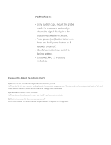
Liquid Measuring Thermostat System
To assure a consistent temperature, place bottle probe
approximately 3 feet away from the air output and not
in the flow of the air.
.

Page 12 XLT 020111
Placement of Unit
Slide the unit from the outside wall into your wine cellar with the outer flange flush to the outside wall.
Secure the flange to the wall through the predrilled holes. The screws should penetrate the studs as
well as the upper and lower supports to provide adequate support for the WhisperKOOL System (see
illustration). Seal all cracks and gaps around the WhisperKOOL unit with caulking to prevent air leakage.
(If you use molding, it should be attached to the walls, never to the WhisperKOOL unit itself.)
Electrical Outlet
The unit is equipped with two electrical outlets, one for installation inside the cellar and the other for
installation outside the cellar. Both outlets are initially covered and secured with screws. Select the out-
let to be used and remove that cover; the unused outlet must remain covered to avoid live electrical
charge. Remove side electrical outlet cover for easy through the wall installation. Immediately replace
cover when install is completed and prior to powering up unit if electrical cord is not attached to outlet.
Installing Thermostat
Attach the thermostat to the front of the unit using the mounting bracket. Make sure the black male
plastic plug from the unit is securely fitted into the female plug located on the circuit board of the
thermostat. To complete the installation, insert the small black screws into each side of the thermostat
PDT/PDT Jr. securing it to the mounting bracket. Insert the probe into a wine bottle 3/4 full of water.
Slide unit, outside-in, into your cellar, and secure all screws rmly to the studs and supports.
Attach the PDT mounting bracket.
Attach the PDT to the mounting bracket.
Wall Stud
Two-by-Four Upper Support
Wall Stud
2” x 4”
Lower Support
Electrical Outlets
Drain line

Page 13 XLT 020111
Drain line
T-Fitting
WRONG: Drainline is under water.
USING THE WHISPERKOOL SYSTEM
®
FRONT
REAR
OFF
POWER
Location of control switches
Switches
Power Switch
XLT units, built after June 2007, come equipped with a
3-position ON/OFF power switch. The upper position activates
power from the cellar side outlet located on the side of unit. The
bottom position activates power from the rear position outlet.
The center position is OFF and is simply used when the owner
does not need to utilize the equipment.
NOTE; (It will take five minutes before the unit begins to
operate once the switch is placed in the “On” position. This
is due to the designed safety delay in the PDT thermostat.)
Condensate Evaporator Switch
The Condensate Evaporator is a heating element that automatically evaporates excess condensate that
accumulates in the cooling system as a by-product of refrigeration. Only the WhisperKOOL units are
equipped with sophisticated heating elements that automatically sense the presence of water and work
continually until the water is gone. Setting the Condensate Evaporator to the “On” setting causes the
heating element and the right exhaust fan to stay on continuously to prevent excess condensation from
building up in the unit.
Drain Line
All units come with a drain line for additional
removal of excessive condensate. This is a back up
system to the Condensate Evaporator. It is
mandatory to install the drain line attachment.
During operation, the cooling unit will strip excess
water from the air in order to maintain the proper
level of humidity within the cellar. The Condensate
Evaporator will heat and dissipate the excess
moisture through the rear of the unit. However in
extreme humidity, additional condensate will be
created. Conversely the high humidity air has less
capacity to absorb additional moisture through the
exhaust of the unit. Thus the drain line will prevent
overflow and leaking by allowing for discharge of
the additional condensate. WhisperKOOL carries a
condensate pump kit, which allows the excess
condensate to be pumped up to 20 ft. away from
the unit. See page 29 for details.
Failure to install the drain line voids warranty.
To prevent mold from growing, allow the
drainline to hang above the water line.

Page 14 XLT 020111
LIQUID MEASURING THERMOSTAT SYSTEM
Room-temperature
Water
Fill an empty bottle with room-temperature
water; then insert the probe.
All WhisperKOOL units come equipped with our Pre-
cision Digital Technology (PDT/PDT JR) liquid tem-
perature measuring thermostat system. This system
incorporates the following advantages:
1. Self-Calibrating Probe: The probe contains a
sensor chip, which actually communicates back
and forth to the thermostat. This results in a con-
sistent temperature setting and accuracy. Do not
remove the tip from the probe!
2. Built in Defrost Cycle: The unit is designed to shut
off for five minutes every ninety minutes in order
to prevent frost build up. This allows the cooling
unit to continue to cool effectively in demanding
environments. A count down timer is observed
by depressing the center button on the thermo-
stat. (PDT upgrade version only)
3. Heavy-duty Circuitry: The circuitry within this
new unit has been upgraded to resist power
surges, which play havoc on electrical compo-
nents. This improvement will ensure years of
trouble-free use. However, for high reliability, we
still recommend that the customer install a surge
protector for the unit itself.
4. Fahrenheit and Celsius Readout (PDT upgrade
version only): The thermostat has the ability to
produce the readout in both Fahrenheit and Cel-
sius for overseas customers. The readout can be
changed by depressing both the center and right
buttons at the same time.
Measuring liquid temperature has a few unique
advantages:
1. Wine temperature is kept in a very precise con-
trolled environment. This assures a consistent
temperature.
2. By measuring the liquid temperature rather
than air, the unit will operate 75- 80% of the
time. See page 2.
To Use the thermostat:
1. Locate an empty wine bottle.
2. Fill 3/4 full with room temperature tap water.
3. Place bottle probe securely into bottle.
4. Place bottle with probe in a central location of
your wine cellar.
Avoid pulling too much on the probe cord. It may
become disconnected resulting in non operation
of the unit.
Note: Thermostat can be set between 50°F and
76°F.
Remember: The WhisperKOOL System is based on
the temperature of the wine. Do not be misled by
thermostats reading air temperature. The air tem-
perature in the cellar will be cooler than the liquid
temperature of the wine while it is coming to opti-
mum balanced temperature.

Page 15 XLT 020111
Operating Instructions for WhisperKOOL PDT JR. Thermostat
Indicators
There are three colored lights on the left side of the thermostat:
• PWR (Green) – When this light is on, the unit is powered.
• RUN (Yellow) – When this light is on, the compressor is running. If the light is flashing,
the unit is currently in the five-minute lockout.
• SET (Red) – This light flashes when the set-point temperature is changed by pressing
one of the three control buttons (see below). It flashes once for each press of the (⇑) or
(⇓) button, and twice when the 55 button is pressed.
When the unit is first turned on, all three lights flash slowly while the thermostat starts up.
Once the unit completes its start-up check, the compressor is locked out for five minutes.
During this time the RUN light will be flashing slowly (1 flash per second).
All three lights will flash rapidly if there is no probe connected to the thermostat.
Buttons
To change the set-point temperature, press either the (⇑), (⇓), OR (55) buttons. The SET
light will flash once for each 1°F the set-point is changed. This set-point will remain in
memory until you change it.
If you forget where the unit is set, pressing the (55) button will reset the set-point to
55°F and the SET light will flash twice. The temperature cannot be adjusted below 50°F
or above 76°F. Attempting to set the unit outside this range will cause the SET light to
rapidly flash.
Operation
Whenever the compressor shuts off normally, a five-minute lockout period begins and
the RUN light will be flashing slowly (1 flash per second).
If the compressor runs for 90 continuous minutes, a five-minute defrost cycle is forced,
during which time the compressor will not run. During this defrost cycle the RUN light
will be flashing rapidly (2.5 flashes per second).
PDT JR OPERATING INSTRUCTIONS

Page 16 XLT 020111
1. Wine Temperature Indicator: A red LED bar will light up when the thermostat is
reading the liquid temperature in the bottle via the probe. This will remain lit and
the temperature you see displayed is what the probe is reading.
2. LED Screen: Displays your thermostat readings.
3. Wine Temperature Reading: The temperature the water bottle is registering to
the thermostat.
4. Temperature SET Indicator: A red LED bar will light up when you are setting the
temperature.
5. Unit ON Indicator: A red LED bar will light up every time the unit turns on to run
a cooling cycle.
6. SET Button: Used to set the temperature you want the unit to maintain.
7. UP Arrow Button: Used with the SET button to set temperature higher. In addi-
tion, by pressing and holding the button it will allow you to see the 5-minute count
down.
8. DOWN Arrow Button: Used with the SET button to set temperature lower.
*Up and Down Arrow Buttons used simultaneously will change the tempera-
ture read out from Fahrenheit to Celsius*
PDT OPERATING INSTRUCTIONS
WINE Temperature Indicator
Wine Temperature Reading
LED Screen
1
3
2
4
5 6
7
8
Temperature SET Indicator
Button
UP Arrow Button
DOWN Arrow Button
Unit ON Indicator Button
SET Temperature Button
Temperature
Precision digital Technology Thermostat
PDT
WINE
ON
SET
55
F
SET
The unit is set at 55°F at the factory. To raise or lower the set temperature, press the set button while at the
same time pressing either the arrow up or arrow down button.

Page 17 XLT 020111
NORMAL OPERATION
WhisperKOOL
systems are designed to maintain both temperature and humidity. Once the system is
installed and the temperature set, it will run continuously until the wine cellar is at your set wine
temperature. This may be as long as three weeks, depending on the size of the room, the quality
(R-value) of insulation, the original temperature of the wine, and the number of bottles residing in the
cellar. Once the cellar has achieved the set temperature, the WhisperKOOL unit will cycle to maintain
±1°F of your set temperature.
Note: Defrost Cycle will turn off the unit for 5 minutes every 90 minutes to allow any accumulated
frost to dissolve.
The WhisperKOOL
system will run more often than a refrigerator or air conditioner, due to its
gentle cooling and humidity maintenance.
People often make the mistake of comparing the performance of refrigerators with the performance
and cycling of wine storage equipment. Wine cellar cooling systems are highly specialized and designed
for one purpose only–long term storage of wine.
Maintenance
The following maintenance should be performed on your WhisperKOOL
unit at least once every six
months to promote longevity and optimal performance.
Vacuum the WhisperKOOL
unit to clean the evaporator and condenser coils to prevent air blockage. The
condenser coils reside behind the grill on the back of the WhisperKOOL
unit. Don’t try to open the unit
yourself. Just vacuum the surface of the grill and remove any lint or dust that has accumulated.
Humidity Control
There are no separate switches in order to maintain humidity. The cooling unit is designed to maintain
relative humidity at 50-70%.
The WhisperKOOL units do not create humidity. If you live in a dry area of the country you many need
to create humidity in the wine cellar. This can be done by introducing a non-heat humidifier, or installing
a small fountain within the cellar.
MAINTENANCE SCHEDULE
Monthly 1. Check for unusual noise or vibration
2. Check the drainline to see if it is above the waterline if draining into a vessel.
Quarterly 1. Clean front and rear intake grilles.
Annually 1. Use a vacuum with brush attachment to clean grilles.
2. Inspect for corrosion.
3. Check wiring connections and integrity of cords.
4. Pour a 50/50 bleach solution into the drainline every spring.
It is the user’s responsibility to remove any accumulated dust, lint, or other debris from the front and rear intake
grilles. This will restrict the airow and may aect the unit’s ability to function properly. Periodically cleaning the
unit’s vents will help assure maximum cooling eciency. The drain tube must also be checked and kept clean and
free of debris and mold to maintain proper performance.

Page 18 XLT 020111
DUCTING
A WhisperKOOL XLT ducting kit is available for purchase. The kit allows the warm air to exhaust to several places such
as an attic, an adjacent room, or outside. The goal is to get the warm exhaust air away from the rear intake of the unit.
The customer will need to purchase 8” ex ducting, along with any hangers needed to run the ducting outside.
See page 29 for more information on purchasing a XLT ducting kit.
Using the Thermostat Controller
The in-line fan will turn on and push warm exhaust air away from the WhisperKOOL® unit, preventing
the unit from overheating. The in-line fan is capable of moving warm air through 25 feet of 8” ex
ducting (not included). The in-line fan can be set to automatically turn on at varying temperatures in
order to conserve the most electricity.
Setting the Thermostat Controller to its lowest setting will turn the fan on at lower temperatures
(Around 70° F). Setting the Thermostat Controller to its highest setting will turn the fan on at higher
temperatures (Around 100° F). If the unit isn’t cooling properly, setting the thermostat controller to a
lower setting may x the problem.
S
T
A
R
T
I
N
G
T
E
M
P
E
R
A
T
U
R
E
LO HI
EXHAUST SIDE
Shown here: Ducting through ceiling
85°F Max
Temperature
Plug
8” ex ducting
Drainline
XLT Ducting Kit
/