Sigma Heat Pump S2Ca User manual
- Category
- Power heat guns
- Type
- User manual
This manual is also suitable for

Part No. 987282 ProMinent Dosiertechnik GmbH · 69123 Heidelberg · Germany BA SI 018 10/03 GB
ProMinent
®
Please completely read through these operating instructions first! · Do not discard!
The warranty shall be invalidated by damage caused by operating errors!
Two sets of operating instructions are necessary to ensure the ProMinent
®
Sigma/ 2 S2Ba or S2Ca metering pumps
are operated safely and reliably for their intended purpose:
This product specific Sigma/ 2 operating instructions manual and the ”General operating instructions
ProMinent
®
motor-driven metering pumps and hydraulic accessories” are only valid if read together!
Operating Instructions
ProMinent
®
Sigma/ 2
S2Ba (Basic Type)
S2Ca (Control Type)
S
T
A
R
T
S
T
O
P
S2Ba S2Ca
Please enter the identity code of the device here.
S2Ba
___ ___ ___ ___ ___ ___ ___ ___ ___ ___ ___ ___
S2Ca
___ ___ ___ ___ ___ ___ ___ ___ ___ ___ ___ ___ ___ ___ ___

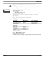
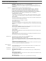
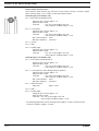
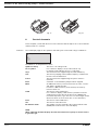
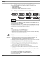
Control elements: overview
1 Operating light (green)
2Warning light (yellow)
3 Error warning light (red)
4 Stroke length adjuster
5 LCD display
6 UP key
7 DOWN key
8P key
9 STOP/START key
10 i key
11 Relay output (optional)
12 Metering monitor socket
13 Float switch socket
14 External control socket
15 Diaphragm rupture indicator socket
16 Mains switch
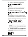
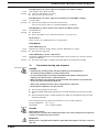
Key functions
In continuous display mode In settings mode
(operating) (settings)
STOP/START key
STOP
START
Press briefly Stop pump, Stop pump,
start pump start pump
P key
P
Press briefly Start batch (in “batch” operating mode only), Confirm entry- jump to next menu
Cancel error option or continuous display
Press for 2 s Change to settings mode ---
Press for 3 s --- Jump to continuous display
Press for 10 s Software version displayed
Press for 15 s Load factory settings (calibration) ---
i key
i
Press x1 Toggle between continuous displays Toggle between “change individual digits”
and change a figure"
Press x2 --- For “change individual digits”:
jumps to first digit
Arrow keys UP and DOWN
Press separately Change directly alterable values Select other settings,
(until “Set” appears) change individual digit or figure
Press simultaneously Prime (in “stroke rate” permanent display) ---
Control elements and key functions
1
2
3
16
4
9
10
8
5
6
7
15 14 13 12 11

P
P
P
P
P
P
P
P
P
P
P
P
P
P
P
P
P
P
P
P
P
P
P
P
P
P
P P
P
P
i
STOP
STOP
START
START
Batch
Contact
ManualAnalog
Analog
Manual
Contact
Batch
Set
mA
Set
Analog
mA
Set
Analog
Set
Analog
mA
Set
Analog
mA
Set
Analog
Freq.
Set
Analog
Freq.
Set
Analog
Freq.
Set
Analog
Freq.
Set
Analog
Freq.
Set
Analog
Freq.
Set
Analog
Freq.
Set
Analog
Freq.
Set
Analog
Freq.
Set
Analog
Freq.
Set
Analog
Freq.
Set
Analog
Freq.
Set
Analog
mA
Set
Analog
mA
Set
Analog
mA
Set
Analog
mA
Set
Analog
mA
Set
Analog
mA
Set
Analog
mA
Set
Analog
mA
Set
Analog
mA
Set
Analog
mA
Set
Analog
Set
Analog
Set
Analog
2 s
Set
Analog
Set
Analog
Set
Analog
2
1
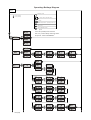
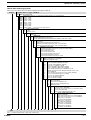
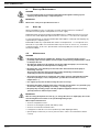
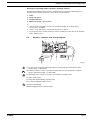
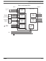
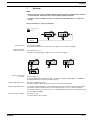
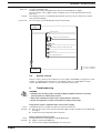
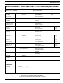
Operating-/Settings Diagram
Continuous
display
Start/stop pump
Change directly alterable values
= Lock (CODE 1)
= Lock (CODE 2)
Prime
Start batch (in"batch" operating mode only)
Cancel error
Check adjustable values
2
1
p. 45
p. 52
p. 44
p. 51
next page
Select the operating mode here first,
then carry out the settings in the SET menu.
Exceptions: Timer and PROFIBUS
®
.

Set
P
Set
Set
Set
Calib
Set
Calib
Set
Set
Set
p. 51
p. 49
p. 51
p. 49
p. 50
p. 34
p. 51
previous page

i
i
i
i
i
i
i
i
i
i
i
i
i
i
i
i
i
i
i
i
i
i
i
i
i
i
i
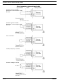
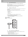
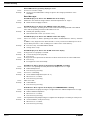
N
*
Mem
Contact
Stop
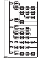
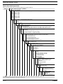
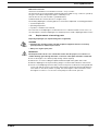
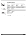
Operating mode "
Analog" 0-20 mA
Stroke rate
Feed rate
Total stroke number
Total litres
(feed quantity)
"External" display
Signal current
Strokes remaining
Batch size/
Litres remaining
Factor
"Mem" appears only when "memory" function activated
Stroke length
Operating mode "
Manual"
Continuous display
Operating mode "
Contact" with
memory and tansfer factor 5
Operating mode "
Batch" with
memory and tansfer factor 5
N
Analog
Stop
L
Analog
Stop
Analog
Stop
mA
Analog
Stop
%
Analog
Stop
%
Manual
Stop
%
Contact
Stop
%
Batch
Stop
Freq.
Manual
Stop
Freq.
Contact
Stop
N
Stop
Contact
Freq.
Batch
Stop
N
Stop
Batch
/hL
Manual
Stop
N
Stop
Manual
L
Stop
Contact
L
Stop
Batch
L
Stop
Manual
Stop
Contact
Mem
Stop
Batch
Mem
N
*
Mem
Batch
Stop
L
*
Mem
Batch
Stop
*
Mem
Batch
Stop
*
Mem
Contact
Stop
Freq.
Analog
Stop
/hL
Analog
Stop
Continuous
display
= UP and/or DOWN arrow keys, directly alterable values
Operating mode ”Contact” with
memory and transfer factor 5
Operating mode ”Batch” with
memory and transfer factor 5

Page 6
ProMinent
®
Dulcodes UV-Desinfektionsanlage
Imprint
Operating Instructions for ProMinent
®
Sigma/ 2 S2Ba/S2Ca
© ProMinent Dosiertechnik GmbH, 2002
ProMinent Dosiertechnik GmbH
Im Schuhmachergewann 5-11
69123 Heidelberg · Germany
www.prominent.de
Subject to technical modifications.
Imprint

Dulcodes UV-Desinfektionsanlage
Page 7
ProMinent
®
Table of contents
Page
Device Identification/Identcode 9
1 Notes on safety of ProMinent
®
metering pumps 11
1.1 Summary of additional safety instructions for the EX version
of the pump (in accordance with ATEX) 11
1.2 General notes 13
1.3 Notes on installation, start-up and operation 13
1.4 Notes on maintenance and repair 14
2Product description S2Ba/S2Ca 15
2.1 Identification of pump type 15
2.2 Design/Functional description 15
2.2.1 Functional description, drive 15
2.2.2 Stroke movement 16
2.2.3 Metering capacity diagram 17
2.2.4 Functional description, delivery unit 19
2.2.5 Integrated overflow valve with bleeder function 20
2.2.6 Diaphragm rupture sensor 22
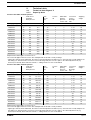
3Technical data 25
3.1 Technical data Sigma/ 2 25
3.1.1 Capacity data 25
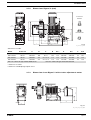
3.1.2 Dimensions Sigma/ 2 27
3.1.3 Dimensions Sigma/ 2 with stroke adjustment motor 27
3.1.4 Motor data 28
3.1.5 Stroke actuator drive mechanism 28
3.1.6 Stroke adjuster drive mechanism 28
3.1.7 Electrical data, stroke sensor “Sigma” 28
3.1.8 Electrical data, pacing relay “Sigma” 29
3.1.9 Sound intensity level 29
4 Start-up/Maintenance 30
4.1 Start-up 30
4.2 Maintenance 30
4.3 Replacement of wearing parts 31
5 Features of the S2Ca metering pumps 33
5.1 Function description, motors 33
5.2 Function description, controller 33
5.3 Sockets, symbols and wiring diagram 35
5.4 Retrofitting relays 41

Page 8
ProMinent
®
Dulcodes UV-Desinfektionsanlage
Table of contents
6 Control elements 42
7 Settings 43
7.1. Check adjustable values 44
7.2 Change to settings mode 44
7.3 Select operating mode (MODE menu) 44
7.4 Settings for operating mode (SET menu) 45
7.4.1 Settings for “manual” operating mode 45
7.4.2 Settings for “analogue” operating mode (ANALG menu) 45
7.4.3 Settings for “contact” operating mode (CONTCT menu) 47
7.4.4 Settings for “batch” operating mode (BATCH menu) 49
7.5 Settings for programmable functions (SET menu) 50
7.5.1 Settings for “calibration” function (CALIB menu) 50
7.5.2 Settings for “auxiliary frequency” function (AUX menu) 51
7.5.3 Settings for the “flow” function (FLOW menu) 51
7.6 Setting code (CODE menu) 51
7.7 Cancel total stroke number or total litres (CLEAR window) 51
8 Operating 52
8.1 Manual operation 52
8.2 Remote control 53
9Troubleshooting 53
10 Decommissioning and disposal 55
11 Spare parts and accessories 56
Annex 57
Motor data sheet 57
EC Declaration of Conformity 58
Exploded diagrams of liquid ends 59
Stroke actuator wiring diagram 63
Wiring diagram, stroke length adjuster 63

Dulcodes UV-Desinfektionsanlage
Page 9
ProMinent
®
Dulcodes UV-Desinfektionsanlage
Identcode ordering system
ProMinent
®
Identcode ordering system
Please enter the identcode on the device label into the grey box below.
S2Ba Sigma Basic Type (S2Ba)
HM Main drive, diaphragm
Pump type: (figures 1+2 = back pressure [bar], figures 3-5 = feed rate [l/h])
16050
16 bar; 50 l/h
16090
16 bar; 90 l/h
16130
16 bar; 130 l/h
12050*
10 bar; 48 l/h
12090*
10 bar; 86 l/h
12030*
10 bar; 125 l/h
07120
7 bar; 120 l/h
07220
7 bar; 220 l/h
04350
4 bar; 350 l/h * for SST versions, max. 12 bar
Liquid end materials:
PV PVDF
SS Stainless steel
Seal material:
T PTFE seal
Diaphragm:
0 Standard diaphragm, PTFE version
1 Double diaphragm with diaphragm rupture indicator (retro fit possible)
Liquid end version:
0 No spring
1 With 2 valve springs, Hastelloy C, 0.1 bar
4 With pressure relief valve, Viton
®
seal, no valve spring
5 With pressure relief valve, Viton
®
seal, and valve spring
Hydraulic connection:
0 Standard threaded connector (according to technical data)
1 Union nut and PVC insert
2 Union nut and PP insert
3 Union nut and PVDF insert
4 Union nut and stainless steel insert
7 Union nut and PVDF hose nozzle
8 Union nut and stainless steel hose nozzle
Version:
0 With ProMinent
®
logo (standard)
1 Without ProMinent
®
logo
Electrical power supply:
S3 ph, 230 V/400 V 50/60 Hz, 0.18 kW
M1 ph, AC, 230 V/50/60 Hz, 0.18 kW
N1 ph, AC 115 V 60 Hz, 0.18 kW
L3 ph, 230 V/400 V, 50 Hz, (EExe, EExde)
P3 ph, 230 V/400 V, 60 Hz, (EExe, EExde)
R3 ph, variable speed motor, 230/400 V, 0.37 kW
VVariable speed motor with integrated speed control 1 pH,
230 V, 50/60 Hz
Z1 ph, variable speed control set 1 ph, 230 V, 50/60 Hz
1 No motor, with B14 flange (Gr. 71 (DIN))
2 No motor, C 56 flange (NEMA)
3 No motor, B5 Gr. 63 (DIN)
4 No motor, B5, Gr. 70 (DIN)
Motor version:
0 IP 55 (standard)
1 Exe version (II 2G EExe II T3)
2 Exde version (II 2G EExde IIC T4)
AATEX type drive
Stroke sensor:
0 No stroke sensor (standard)
1 with stroke sensor (Hall sensor, no connection cable)
2 Pacing relay (reed relay)
3 Stroke sensor (Namur) intrinsically safe
Stroke length adjustment:
0 Manual (standard)
1 With stroke positioning motor, 230 V/50/60 Hz
2 With stroke positioning motor, 115 V/50/60 Hz
3 With stroke control motor,
0...20 mA 230 V/50/60 Hz
4 With stroke control motor
4...20 mA 230 V/50/60 Hz
5 With stroke control motor
0...20 mA 115 V/50/60 Hz
6 With stroke control motor
4...20 mA 115 V/50/60 Hz
S2Ba ___ ___ ___ ___ ___ ___ ___ ___ ___ ___ ___ ___
Viton
®
is a registered trademark of DuPont Dow Elastomers.

Page 10
ProMinent
®
Dulcodes UV-Desinfektionsanlage
Identcode ordering system
Identcode ordering system
Please enter the identcode on the device label into the grey box below.
S2Ca Sigma Control Type (S2Ca)
HM Power end, diaphragm
Pump typ: (figures 1+2 =back pressure [bar],figures 3-5 =feed rate [l/h])
16050
16 bar; 60 l/h
16090
16 bar; 95 l/h
16130
16 bar; 136 l/h
12050* 10 bar; 60 l/h
12090* 10 bar; 95 l/h
12130* 10 bar; 136 l/h
07120
7 bar; 148 l/h
07220
7 bar; 232 l/h
04350
4 bar; 350 l/h * for SST versions, max. 12 bar
Liquid end materials:
PV PVDF
SS Stainless steel
Seal material:
T PTFE seal
Displacement element:
0 Standard diaphragm
1 Double diaphragm with rupture indicator incorporating “Pump stopping” function
2 Double diaphragm with rupture indicator incorporating “Pump alarm” function
Liquid end version:
0 No springs
1With 2 valve springs,Hastelloy C,0.1 bar
4With relief valve,Viton
®
seal,no valve spring
5With relief valve,Viton
®
seal,with valve spring
Hydraulic connection:
0 Standard threaded connector (according to technical data)
1 Union nut and PVC insert
2 Union nut and PP insert
3 Union nut and PVDF insert
4 Union nut and stainless steel insert
7 Union nut and PVDF hose nozzle
8 Union nut and stainless steel hose nozzle
Version:
0 With ProMinent
®
logo
1 Without ProMinent
®
logo
Electrical power supply:
U1 ph 100-230 V ±10 %, 50/60 Hz
Cable and plug:
A2 m European
B2 m Swiss
C2 m Australian
D2 m USA
Relays:
0 No relay
1 With fault indicating relay (N/C)
3 With fault indicating relay (N/O)
4 As 1 with pacing relay
5 As 3 with pacing relay
F Power relay N/C
G Power relay N/O
Control variant:
0 Manual + external with pulse control
1 Manual + external + pulse control
+ analogue
4 As 0 + process-timer
5 As 1 + process-timer
P PROFIBUS
®
Access code:
0 No access code
1 With access code
Metering monitor:
0 Input with pulse evaluation
1 Input with permanent contact
evaluation
Stroke length
adjustment:
0 Manual
C Manual + calibration
S2Ca ___ ___ ___ ___ ___ ___ ___ ___ ___ ___ ___ ___ ___ ___ ___
Viton
®
is a registered trademark of DuPont Dow Elastomers.

Dulcodes UV-Desinfektionsanlage
Page 11
ProMinent
®
Notes on safety of ProMinent
®
metering pumps
1 Notes on safety of ProMinent
®
metering pumps
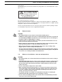
General user instructions
Please read through the following user instructions carefully! They will help you get the best use
out of the operating instruction manual.
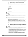
The following are highlighted in the text:
• Enumerations
왘 Instructions
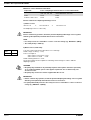
Operating guidelines:
NOTE
Notices are intended to make your work easier.
and safety guidelines:
WARNING
Describes a potentially dangerous situation. If not avoided. could cause fatal or serous
injury.
CAUTION
Describes a potentially dangerous situation. If not avoided. could cause slight or minor
injury or damage to property.
IMPORTANT
Describes a potentially damaging situation. If not avoided. could cause damage to
property.
Please also note the guidelines in “General Operating Instruction Manual for ProMinent
®
Motor-
Driven Metering Pumps and Hydraulic Accessories”!
EX-pump only: The nameplates affixed to the title page are identical to those on the pump
supplied to enable clear identification on the correct operating instruction manual for the pump.
Please give the order number and the serial number, which you will find on the nameplates of the
pump itself, in the event of any query or spare part order. This facilitates identification of the
pump.
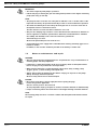
1.1 Summary of additional safety instructions for the EX version
of the pump (in accordance with ATEX)
WARNING
• In explosion-threatened workplaces in zone 1, device category II 2G of explosion group II C
the pump may not be operated without the corresponding rating plate (and the corre-
sponding EC conformity declaration) for pumps for explosion-threatened workplaces in
accordance with guideline 94/9/EC of the European guidelines.
•From July 1st, 2003 on, only pumps with the corresponding marking according to EC-Ex-
directive 94/9 may be used in industrial premises with potentially explosive atmospheres.
The explosion group, category and type of protection shown on the marking must
correspond to or exceed the conditions prevailing in the intended area of application.
• All other uses or modifications are prohibited!
• Pumps may never be operated in explosion-threatened workplaces without a correspond-
ing rating plate (and the corresponding EC conformity declaration) for pumps for
explosion-threatened workplaces.

Page 12
ProMinent
®
Dulcodes UV-Desinfektionsanlage
Notes on safety of ProMinent
®
metering pumps
• Installations in potentially explosive atmospheres must be inspected by an “accredited
qualified” person. This applies in particular also for intrinsically safe electrical circuits.
• Drive motors must be secured by an appropriate motor protection switch. A motor
protection approved for this application must be used for Ex“e”-motors. (Protection
against heating due to overload)
• Observe all relevant standards e.g. DIN EN 60079, DIN EN 50020, DIN VDE 0165 and/or
DIN VDE 0118 “Installing electrical equipment in explosion-threatened areas”!
• When installing the metering pump, observe the directives for the installation of devices
in explosion-threatened areas, e.g. for Europe the European operator’s guideline 99/92/EC
(ATEX137)*, (in Germany implemented via the new operating safety ordinance (Official
Federal Gazette for 2002, Part 1, No. 70, issued in Bonn 2.10.2002))!
* previously ElexV
• Observe documents supplied with individual electric components!
• On principle, metering pumps in potentially explosive atmospheres must be equipped
with a safety overflow valve at the outlet side of the pump (serves as protection against
overheating due to overload and against sparks produced by shock due to overload
which has led to the breakage drive parts.)
• When using with flammable media:
- Diaphragm pumps with mechanically actuated diaphragm: no additional measures
necessary, however, version with diaphragm rupture indicator, version Ex“i”*, must be
used on principle.
- For all metering pumps for metering inflammable media applies: starting up and
emptying only supervised by a competent person.
- Inflammable media may only be lifted with stainless steel liquid ends. - For exceptional
cases, where this is not possible, also PTFE with carbon may be used, our versions TT_
are made of conductive plastics. In this case, special attention must be paid by the
user due to the lower mechanical stability.
• If using the metering pump for Europe e.g. the European operator’s guideline 99/92/EC*
(ATEX 137**), (in Germany implemented via the new operating safety ordinance (Official
Federal Gazette for 2002, Part 1, No. 70, issued in Bonn 2.10.2002) and the German
dangerous chemicals ordinance))!
* previously Ex Vo, Vb F
** previously ATEX118A
• Observe also all relevant standards e.g. DIN EN 60079-10/14 and DIN EN 50020 for
installations in explosion-threatened areas!
• Note all national directives which apply to the installation!
•Wear parts (diaphragms, bearings etc.) of metering pumps used in potentially explosive
atmospheres must be replaced after having completed 90% of their nominal product life.
• The lubricant supply must be regularly checked for lubricated pumps, for instance by
checking the fill level, visual inspection for leakages etc.
• The proper general function, in particular of the drive, must be safeguarded by regular
inspections (leakages, noises, temperatures, possible discoloration due to excess
temperatures....).
• Use original spare parts should exchange become necessary!
• Check that the pressure relief valve downstream from the pump is functioning correctly!
The pressure relief valve must prevent the gearbox from being overloaded and over-
heating in explosion-threatened workplaces!
• When cleaning plastic parts, attention must be paid to not generating any electrostatic
charge by rubbing excessively. - see danger sign.
• These measures are the minimum protection measures specified by ProMinent. Should
the user know about any further risks, it is his duty to eliminate them by taking
corresponding measures.

Dulcodes UV-Desinfektionsanlage
Page 13
ProMinent
®
Safety devices
The following safety notice must be affixed to the pump (with PP, PC and PV liquid ends, acrylic
glass cover, ...)
Because of danger of electrostatical
ignition use damp cloth only
for wiping plastic parts!
ATTENTION
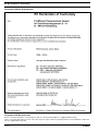
EC conformity declaration / certificates
The EC conformity declaration for pumps for explosion-threatened workplaces is supplied with
the pump (the copy of the EC conformity declaration for the pump itself does not apply to pumps
designed for explosion-threatened workplaces).
The EC conformity declarations, the EC series prototype test reports and the operating manuals
for the individual components are also supplied with the pump.
1.2 General notes
WARNING
• The equipment/devices may only be used for their intended purpose.
•ProMinent
®
metering pumps must not be assembled with parts which are not tested and
recommended by ProMinent otherwise this can lead to injury to persons and damage to
property for which no liability will be accepted!
• Pumps must be accessible at all times to facilitate operation and maintenance. Access
points must not be obstructed or blocked!
• Before carrying out any maintenance and repair work always drain off and flush out the
liquid end first if hazardous or unknown metered media are used!
• When metering hazardous or unknown liquids, always wear safety clothing (safety
goggles, gloves, ...) when working on the liquid end!
•You must observe the guidelines in this operating instructions manual and the ”General
operating instructions manual for ProMinent
®
motor-driven metering pumps and hydraulic
accessoires” on assembly, installation and maintenance!
1.3 Notes on installation, start-up and operation
WARNING
• The metering pump can contain water residue in the liquid end as the result of testing at
the factory!
If handling media which must not come in contact with water, all traces of water must be
removed from the liquid end before start-up! For this purpose, turn the pump through
180˚ and drain off the liquid end then flush with a suitable medium from above via the
intake connection!
• Do not connect mains voltage to the control cable!
• When operating the metering pump against a closed shut-off element on the pressure
side or in the event of pressure peaks during the metering stroke, the system pressure
can reach a multiple of the maximum permissible operating pressure that can conse-
quently cause the pressure line to burst!
•To avoid this situation, an overflow is recommended for the purpose of limiting the
maximum permissible operating pressure of the pump or system.
• Do not connect a metal bypass line to the overflow valve on the PVT delivery unit! This
could cause cracks in the delivery unit!
Notes on safety of ProMinent
®
metering pumps

Page 14
ProMinent
®
Dulcodes UV-Desinfektionsanlage
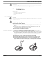
IMPORTANT
• Set stroke length only with pump in operation!
• Pull the red plug for venting the gear unit during initial operation of the Sigma/ 2 metering
pump (refer to Fig. 2, item 10)!
NOTE
• The pump must be secured in such a way that no vibrations can occur! The valves of the
liquid end must always be positioned vertically in order to ensure trouble-free operation!
• The intake and delivery lines must always be arranged such as to ensure connection at
the liquid end is free of mechanical stress!
The lines must be secured such that no vibrations can occur!
• Only use the clamping rings and hose sockets intended for the relevant hose diameter as
well as original hoses with the specified hose dimensions and wall thickness otherwise
the stability and durability of the connection will not be guaranteed!
Avoid reducing hose sizes!
Observe the permissible pressure of the hoses!
•A vent with return to the supply tank is advisable when metering extremely aggressive or
hazardous media!
In addition, a shut-off valve should be provided on the delivery or intake side!
1.4 Notes on maintenance and repair
WARNING
• Only specially trained and authorized persons are permitted to carry out maintenance on
metering pumps and their peripherals!
• If hazardous or unknown metering media are used, always flush out the liquid end first
before carrying out any maintenance and repair work!
• When metering hazardous or unknown liquids, always wear safety clothing (safety
goggles, gloves, ...) when working on the liquid end!
• Always depressurize the delivery line first before carrying out any work on the pump!
Always discharge and flush liquid end!
Observe safety data sheets for metered liquid!
DANGER
• Disconnect power plug or power supply line before opening the plug!
Isolate relay option if applicable!
Check to ensure power is disconnected!
Secure pump while carrying out repairs to ensure it cannot be switched on unintentionally!
• Pumps for metering radioactive media must not be shipped through standard channels!
NOTE
The metering pump must be in a cleaned condition with the liquid end flushed if returned
for repair!
Notes on safety of ProMinent
®
metering pumps

Dulcodes UV-Desinfektionsanlage
Page 15
ProMinent
®
Product description S2Ba/S2Ca
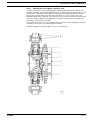
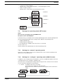
Fig. 1
2Product description S2Ba/S2Ca
WARNING
Use for intended purpose
• The pump is designed as a liquid medium metering pump; it serves the purpose of
metering liquid medium within the specified line system!
• In explosion-threatened workplaces in zone 1, device category II 2G of explosion group II
C the pump may not be operated without the corresponding rating plate (and the corre-
sponding EC conformity declaration) for pumps for explosion-threatened workplaces in
accordance with guideline 94/9/EC of the European guidelines.
•From July 1st, 2003 on, only pumps with the corresponding marking according to EC-Ex-
directive 94/9 may be used in industrial premises with potentially explosive atmospheres.
The explosion group, category and type of protection shown on the marking must
correspond to or exceed the conditions prevailing in the intended area of application.
• Operate the pump only within the conditions described in the technical data!
• General restrictions with regard to viscosity limits, chemical resistance and density must
be observed (refer to ProMinent
®
chemical resistance list (catalogue or homepage))!
• All other applications or conversion are prohibited!
• The pump is not designed to meter gaseous media as well as solids.
• For pumps without EX protection: The pump is not suitable for metering combustible
liquids!
• Pumps may never be operated in explosion-threatened workplaces without a corre-
sponding rating plate (and the corresponding EC conformity declaration) for pumps for
explosion-threatened workplaces.
• Only specifically trained and authorized personnel are permitted to operate the pump!
2.1 Identification of pump type
The identity code and serial number are given in addition to the standard technical specifications.
These two numbers must always be quoted when making any enquiries as they enable distinct
identification of the type of metering pump.
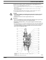
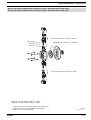
2.2 Design/Functional description
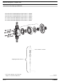
2.2.1 Functional description, drive
The ProMinent
®
Sigma/ 2 diaphragm-type metering pump is an oscillatory displacement pump
with the stroke length adjustable in steps of 0.5 %. It is driven by electric motor (1). The rotary
drive of the electric motor is stepped down by worm gear and transmitted via the eccentric roller
(3) to the push rod (4) connected to fork (8) and converted into oscillatory movement. Return
spring (5) presses the fork with push rod positively against the eccentric roller thus producing the
return stroke. The stroke is adjusted by means of stroke adjustment knob (6) and spindle (7) by
limiting the return stroke. Stroke movement is transmitted directly to the displacement diaphragm.
Interacting with the valves, this diaphragm produces the overpressure and vacuum in the liquid
end necessary for delivery. Flow is pulsating.
In the basic type, the electric motor is normally a 3-ph extended-range AC motor (refer to Section 3
for other options).

Page 16
ProMinent
®
Dulcodes UV-Desinfektionsanlage
0 180 360
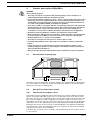
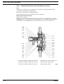
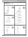
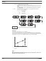
2.2.2 Stroke movement
Set stroke length dependent on the required delivery capacity.
Product description S2Ba/S2Ca
5
6
3
7
1
8
4
10
Fig. 2
61_01-101_00_25-01
NOTE
A large stroke length and low metering frequency should be selected for very viscous
media!
A shorter stroke length and high frequency should be selected to achieve good mixing
properties!
20 0
0
50
25
75
5
75%
0
5
0
25
10
30%
Fig. 4
75 %
30 %
Fig. 3
+ Delivery stroke
b) At reduced stroke length
– Intake stroke
a) Stroke progression
at max. stroke rate
and stroke length
Stroke speed
Angle reduced stroke length

Dulcodes UV-Desinfektionsanlage
Page 17
ProMinent
®
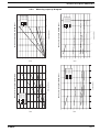
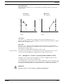
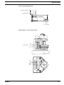
Metering capacity diagram S2Ba HM (50 Hz)
Stroke length in (%)
pressure in (bar)
Metering capacity diagram S2Ba HM (60 Hz)
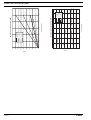
2.2.3 Metering capacity diagram
Product description S2Ba/S2Ca
Metering capacity diagram S2Ba HM (60 Hz)
Stroke length in (%)
pressure in (bar)
Metering capacity diagram S2Ba HM (50 Hz)
0
50
100
150
200
250
300
350
400
450
020406080100 120
Q (l/h)
S2Ba HM 04350
S2Ba HM 07220
S2Ba HM 07120
S2Ba HM 12130
S2Ba HM 12090
S2Ba HM 12050
0
50
100
150
200
250
300
350
400
450
500
Q (l/h)
S2Ba HM 04350
S2Ba HM 07220
S2Ba HM 07120
S2Ba HM 12130
S2Ba HM 12090
S2Ba HM 12050
020406080100120
0
50
100
150
200
250
300
350
400
450
500
02468101214
Q (l/h)
S2Ba HM 04350
S2Ba HM 07220
S2Ba HM 07120
S2Ba HM 12130
S2Ba HM 12090
S2Ba HM 12050
0
50
100
150
200
250
300
350
400
450
02468101214
Q (l/h)
S2Ba HM 04350
S2Ba HM 07220
S2Ba HM 07120
S2Ba HM 12130
S2Ba HM 12090
S2Ba HM 12050

Page 18
ProMinent
®
Dulcodes UV-Desinfektionsanlage
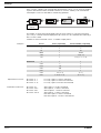
pressure in (bar)
Metering capacity diagram S2Ca HM
Stroke length in (%)
Metering capacity diagram S2Ca HM
Product description S2Ba/S2Ca
0
50
100
150
200
250
300
350
400
450
02 4 6 8101214
Q (l/h)
S2Ca HM 04350
S2Ca HM 07220
S2Ca HM 07120
S2Ca HM 12130
S2Ca HM 12090
S2Ca HM 12050
16
0
50
100
150
200
250
300
350
400
450
020406080100 120
Q (l/h)
S2Ca HM 04350
S2Ca HM 12130
S2Ca HM 07220
S2Ca HM 12090
S2Ca HM 07120
S2Ca HM 12050

Dulcodes UV-Desinfektionsanlage
Page 19
ProMinent
®
Product description S2Ba/S2Ca
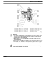
Fig. 5
3154-4
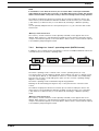
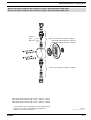
2.2.4 Functional description, delivery unit
The heart of the delivery unit is the DEVELOPAN
®
metering diaphragm (2). It hermetically seals
the delivery chamber of the liquid end (4) and produces a displacement in the liquid end. The end
disc (5) made of chemically resistant plastic together with safety diaphragm (13) separates the
drive housing from the delivery unit and protects the drive from corrosion in the event of the
diaphragm failing. Delivery is based on the interaction between intake valve (1) and head valve (3)
of the same design together with the diaphragm movement. The valve balls can be supported
with springs for metering viscous media.
The connection dimensions of valves and liquid ends of the same size but with different materials
are identical. These parts can be interchanged as required.
Materials and dimensions are specified in Section 3, Technical data.

Page 20
ProMinent
®
Dulcodes UV-Desinfektionsanlage
Product description S2Ba/S2Ca
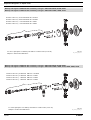
2.2.5 Integrated overflow valve with bleeder function
Task:
The task of the overflow valve is to protect the motor and gear unit against impermissible
overpressure caused by the metering pump.
This function is produced by a spring-loaded ball.
A pressure relief mechanism for the bleeder function is provided.
Design and functional description
(refer to Fig. No. 6 and 7)
Initially, the overflow valve illustrated under item 102 operates as a simple directly controlled
safety valve. As soon as the pressure set with spring item 132 is exceeded, the effective pressure
raises ball item 130. The liquid then flows off into the tank via hose connection item 128.
Fig. 6
3160-4
Overflow valve Sigma/ 2 liquid end, 10 bar PVT Identcode Type: 12050, 12090, 12130
Overflow valve Sigma/ 2 liquid end, 7 bar PVT Identcode Type: 07120, 07220
Overflow valve Sigma/ 2 liquid end, 4 bar PVT Identcode Type: 04350
134
102
133
137
132
138
139*
131
202
203
126
125
127
136
128
130
111
112
100
110
114
115
118
200
201
117
101
113
116
Page is loading ...
Page is loading ...
Page is loading ...
Page is loading ...
Page is loading ...
Page is loading ...
Page is loading ...
Page is loading ...
Page is loading ...
Page is loading ...
Page is loading ...
Page is loading ...
Page is loading ...
Page is loading ...
Page is loading ...
Page is loading ...
Page is loading ...
Page is loading ...
Page is loading ...
Page is loading ...
Page is loading ...
Page is loading ...
Page is loading ...
Page is loading ...
Page is loading ...
Page is loading ...
Page is loading ...
Page is loading ...
Page is loading ...
Page is loading ...
Page is loading ...
Page is loading ...
Page is loading ...
Page is loading ...
Page is loading ...
Page is loading ...
Page is loading ...
Page is loading ...
Page is loading ...
Page is loading ...
Page is loading ...
Page is loading ...
Page is loading ...
-
 1
1
-
 2
2
-
 3
3
-
 4
4
-
 5
5
-
 6
6
-
 7
7
-
 8
8
-
 9
9
-
 10
10
-
 11
11
-
 12
12
-
 13
13
-
 14
14
-
 15
15
-
 16
16
-
 17
17
-
 18
18
-
 19
19
-
 20
20
-
 21
21
-
 22
22
-
 23
23
-
 24
24
-
 25
25
-
 26
26
-
 27
27
-
 28
28
-
 29
29
-
 30
30
-
 31
31
-
 32
32
-
 33
33
-
 34
34
-
 35
35
-
 36
36
-
 37
37
-
 38
38
-
 39
39
-
 40
40
-
 41
41
-
 42
42
-
 43
43
-
 44
44
-
 45
45
-
 46
46
-
 47
47
-
 48
48
-
 49
49
-
 50
50
-
 51
51
-
 52
52
-
 53
53
-
 54
54
-
 55
55
-
 56
56
-
 57
57
-
 58
58
-
 59
59
-
 60
60
-
 61
61
-
 62
62
-
 63
63


Sigma Heat Pump S2Ca User manual
- Category
- Power heat guns
- Type
- User manual
- This manual is also suitable for
Ask a question and I''ll find the answer in the document
Finding information in a document is now easier with AI
Other documents
-
ProMinent S3Ba 070410 PPT Operating Instructions Manual
-
-
-
-
-
Fairchild Lower Pressure Selector Relay User manual
-
-
-
-