Page is loading ...

Description
Two-Wheel, Light-Duty Trailer For Small
Engine-Driven Welding Generators
1000 lb (453 kg) Net Payload Capacity
OM-684 July 1995
Eff. w/Serial Number KD343680
EDT 1000-2B
Visit our website at
www.MillerWelds.com

Miller Electric manufactures a full line
of welders and welding related equipment.
For information on other quality Miller
products, contact your local Miller distributor
to receive the latest full line catalog or
individual catalog sheets. To locate your nearest
distributor or service agency call 1-800-4-A-Miller,
or visit us at www.MillerWelds.com on the web.
Thank you and congratulations on choosing Miller. Now
you can get the job done and get it done right. We know
you don’t have time to do it any other way.
That’s why when Niels Miller first started building arc
welders in 1929, he made sure his products offered
long-lasting value and superior quality. Like you, his
customers couldn’t afford anything less. Miller products
had to be more than the best they could be. They had to
be the best you could buy.
Today, the people that build and sell Miller products continue the
tradition. They’re just as committed to providing equipment and service
that meets the high standards of quality and value established in 1929.
This Owner’s Manual is designed to help you get the most out of your
Miller products. Please take time to read the Safety precautions. They will
help you protect yourself against potential hazards on the worksite. We’ve
made installation and operation quick and easy.
With Miller you can count on years of reliable
service with proper maintenance. And if for
some reason the unit needs repair, there’s a
Troubleshooting section that will help you
figure out what the problem is. The parts list
will then help you to decide which exact part
you may need to fix the problem. Warranty and
service information for your particular model
are also provided.
Miller is the first welding
equipment manufacturer in
the U.S.A. to be registered to
the ISO 9001 Quality System
Standard.
Working as hard as you do
– every power source from
Miller is backed by the most
hassle-free warranty in the
business.
From Miller to You
Miller offers a Technical
Manual which provides
more detailed service and
parts information for your
unit. To obtain a Technical
Manual, contact your local
distributor. Your distributor
can also supply you with
Welding Process Manuals
such as SMAW, GTAW,
GMAW, and GMAW-P.

safety_trailer 10/96
TRAILER TOWING SAFETY PRECAUTIONS
In trailer towing, as in most driving situations, exposure to certain hazards occurs. Trailer towing is safe when
precautions are taken. The following safety information is only a summary of the more complete information found in
the Safety Standards listed at the end of these precautions. Read and follow all Safety Standards. In addition, the
end user must check and comply with all federal, state, and local laws before use.
HAVE ALL INSTALLATION, OPERATION, MAINTENANCE, AND REPAIR WORK PERFORMED ONLY BY
QUALIFIED PEOPLE.
WARNING
TRAILER TOWING can be hazardous.
1. Use a towing vehicle prepared and capable of handling the load.
2. Towing any trailer requires special awareness because of the
changed driving situation.
3. When towing, it takes longer to start, stop, and pass – use
training and practice to avoid accidents.
4. Turning and backing up present new problems – plan ahead.
5. Require each driver to be fully trained and experienced in trailer
towing before going out on the road.
6. Holes are provided for mounting weld/power generator.
7. Be sure trailer is fully prepared and connected to towing vehicle.
8. Observe maximum speed of 45 mph (72 kph) when towing.
9. Do not modify or change the trailer in any way – changes void the
warranty. Read Owner’s Manual.
10. Use only genuine factory parts as replacements.
11. Adjust load on trailer so tongue weight is approximately 10% of
the gross trailer weight and center load side-to-side to reduce
fishtailing.
12. Tighten all parts, bolts, nuts, and mounting hardware.
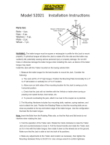
1 Coupler
Hitch is on towing vehicle.
2 Tongue
3 Lights
4 Wheels And
Bearings
5 Rating Plate
6 Jack Stand
7 Safety Chains
1
2
3
3
35
7
6
4
OVERLOADING can cause serious injury or
equipment damage.
1. Do not overload the trailer.
2. The Gross Vehicle Weight Rating (GVWR) is the maximum total
trailer weight with the engine driven welding generator and all
equipment, such as tools, cables, and shielding gas cylinder,
installed.
3. The Gross Axle Weight Rating (GAWR) is the maximum
load-bearing capacity of the axle(s).
4. Weigh trailer – adjust weight by removing accessory equipment if
necessary – call local authorities for nearest scale location.
5. Use gross trailer weight to select a proper towing vehicle.
GVWR – Gross Vehicle
Weight Rating (Maximum
Total Trailer Weight In-
cluding Its Load)
GAWR – Gross Axle
Weight Rating
VIN NO – Vehicle Identifi-
cation Number
Rating
Plate
UNCONTROLLED TILTING OF TRAILER can result
in personal injury or equipment damage.
1. Install generator according to Owner’s Manual with engine end
toward hitch end of trailer.
2. Distribute weight so that trailer tongue weight is approximately
10% of the gross trailer weight.
INCORRECT TONGUE WEIGHT can cause
fishtailing and loss of control of towing vehicle
resulting in serious injury and equipment damage.
3. Tongue weight is the amount of trailer weight that rests on the
towing vehicle hitch – that is, the downward pressure on the
coupler.
4. Remove or adjust trailer load to get correct tongue weight.
5. Do not let tongue weight exceed coupler and hitch rating.
6. Use slower speeds when towing a trailer – never above 45 mph
(72 km/h) – to prevent fishtailing.
Trailer
1
2
3
Gross Vehicle
Gross Trailer Maximum
Up to 2000
(Up to 910)
2000 to 3500
(910 to 1590)
3500 to 5000
(1590 to 2270)
1000 (455)
2000 (910)
2000 (910)
3500 (1590)
3500 (1590)
100 (45)
200 (90)
200 (90)
350 (158)
350 (158)
Pipe
Bathroom
Scale
Approximately
10% Of GTW
Tongue – Level
Board
Class
1
1
Information From SAE
J684 May 1987
2
Gross Trailer Weight
(Actual Loaded Weight)
3
10% Of GTW
Recommended
And
Coupler
Weight Rating
GVWR
lb (kg)
Weight GTW
2
lb (kg)
Tongue Weight
3
lb (kg)
SAFETY CHAINS CAN PREVENT RUNAWAY
TRAILER in case hitch/coupler fails.
1. Always use safety chains when towing.
2. Cross safety chains under coupling to prevent tongue from
dropping to ground.
3. Allow only enough slack for tight turns.
4. Do not let safety chains drag on ground.
5. Twist safety chains equally from hook ends to take up slack.
6. Use safety chains rated equal to or greater than twice the
maximum gross trailer weight rating.
Bottom
View
Side
View

safety_trailer 10/96
INCORRECT SIZE OR RATING OF HITCH can
cause trailer to break loose from towing vehicle.
1. Be sure towing vehicle hitch is correct type, size, and rating to
match coupler.
2. Be sure the hitch is properly installed onto towing vehicle.
3. On optional ball couplers, always insert hitch safety pin before
towing.
4. Make sure hitch and ball are properly sized and match each
other.
Clevis
Lunette
Eye
Ball
Trailer
Tongue
Couplers
OR
Safety Pin
WHEELS MUST BE CHOCKED when trailer is
uncoupled from vehicle.
1. Chock in direction of grade.
2. Position chock snugly behind tire.
3. Place chock square to the tire.
4. Tap chock into place.
5. For added protection, chock both sides of tire.
UNEXPECTED TILTING OF TRAILER can cause
injury and damage.
1. When trailer is uncoupled from towing vehicle, use jack on front
and block rear to prevent tilting.
2. Use proper blocks that are large enough and able to support the
necessary weight.
3. Always chock the wheels when uncoupled.
INCORRECTLY WORKING LIGHTS can cause
accidents.
1. State and Federal regulations require trailers used on highways
to have tail, stop, turn, and side marker lights.
2. Lights are not required for trailers designed for off-road use only.
3. Check all lights and connectors for proper installation and
operation before using the trailer.
4. Check condition of wiring harness leads, plugs, and connections
regularly. Repair or replace damaged parts or wires.
5. Replace any broken lenses, reflectors, or bulbs.
Tail, Stop, And
Turn Lights
Side Marker Lights
INCORRECT TORQUE on lug nuts or INCORRECT
TIRE PRESSURE or BEARING MAINTENANCE can
cause loss of control resulting in serious injury
and equipment damage.
1. Recheck lug nut torque after first 50 miles (80 km) and once each
year or every 12,000 miles (19,500 km) thereafter, whichever
comes first.
2. When checking lug nuts, keep them clean, dry, and unlubricated.
3. Check and repack wheel bearings once each year or every
12,000 miles (19,500 km), whichever comes first.
4. Maintain correct tire pressure according to sidewall data on tire –
underinflation is the most common cause of tire trouble.
5. Check tires for wear every six months.
6. Use only replacement tires of the same size, rating, and capacity.
1
4
2
3
1
4
2
5
3
Wheel
Lug
Nuts
Bearings
Inside Hub
4-Hole Wheels –
Torque Lug Nuts
To 60 ft-lbs (81 N·m)
5-Hole Wheels –
Torque Lug Nuts
To 70 ft-lbs (95 N·m)
Torquing Sequence
INOPERATIVE SURGE-TYPE BRAKES OR
WRONG BREAKAWAY CABLE CONNECTION can
cause accidents.
1. Check brake fluid level before use.
2. Do not use sway control devices – keep coupler free to telescope
during braking.
3. Always connect breakaway cable to towing vehicle – be sure it
has a direct free pull.
4. Do not wrap cable around safety chains, tongue, wiring, or any
other parts.
5. The breakaway cable automatically applies the trailer brakes if
separation occurs.
Self-Actuating Hydraulic
Brake System
Breakaway
Cable
Brake Fluid
Reservoir
Surge-Type
Coupler
Bracket

safety_trailer 10/96
LOOSE OR INCORRECT HARDWARE AND
FASTENERS can cause injury and damage.
1. Periodically double-check all nuts and bolts for tightness and
condition.
2. If necessary, always replace any fastener with one of equal
size, grade, and type.
3. Be sure the grade marks on replacement fastener match the
original bolt. The manufacture’s identification mark is not critical
and does not matter for the replacement fastener.
Grade Marks.
Manufacturer’s
Identification Mark
PRE-TOWING CHECKLIST
Check gross trailer weight, tongue weight, and total weight distribution – do not overload this trailer.
Check that the correct hitch is properly installed on towing vehicle.
When coupling, check that coupler locking device (safety pin), safety chains, and breakaway cable (if applicable) are properly connected.
Check that tires are properly inflated and that wheel nuts are properly torqued.
If applicable, check that all lights are working properly.
PRINCIPAL SAFETY STANDARDS
Trailer & Camper Safety, Publication # DOT HS-802586, from U.S. De-
partment of Transportation, National Highway Traffic Safety Adminis-
tration, Washington, D.C. 20590
Safety and Health Standards, OSHA 49 CFR 200 to 999, from Superin-
tendent of Documents, U.S. Government Printing Office, Washington,
D.C. 20402
SAE Handbook. 1996. Volume 4. On-Highway Vehicles and Off-High-
way Machinery, from Society of Automotive Engineers, Inc., 400 Com-
monwealth Drive, Warrendale, PA 15096-0001.
REPORTING SAFETY DEFECTS
If you believe that your vehicle has a defect which
could cause a crash or could cause injury or death,
you should immediately inform the National Highway
Traffic Safety Administration (NHTSA) in addition to
notifying MILLER Electric Mfg. Co.
If NHTSA receives similar complaints, it may open an
investigation, and if it finds that a safety defect exists
in a group of vehicles, it may order a recall and remedy
campaign. However, NHTSA cannot become
involved in individual problems between you, your
dealer, or MILLER Electric Mfg. Co.
To contact NHTSA, you may either call the Auto
Safety Hotline toll-free at 1-800-424-9393 (or
366-0123 in Washington, D.C. area) or write to:
NHTSA, U.S. Department of Transportation,
Washington D.C. 20590. You can also obtain other
information about motor vehicle safety from the
Hotline.
mod11.1 8/94
TABLE OF CONTENTS
SECTION 1 – SAFETY INFORMATION 1. . . . . . . . . . . . . . . . . . . . . . . . . . . . . . . . . . . . . . . . . . . . . . . . . . . .
SECTION 2 – SPECIFICATIONS 1. . . . . . . . . . . . . . . . . . . . . . . . . . . . . . . . . . . . . . . . . . . . . . . . . . . . . . . . . .
SECTION 3 – ASSEMBLY 2. . . . . . . . . . . . . . . . . . . . . . . . . . . . . . . . . . . . . . . . . . . . . . . . . . . . . . . . . . . . . . . .
3-1. Installing Hardware 2. . . . . . . . . . . . . . . . . . . . . . . . . . . . . . . . . . . . . . . . . . . . . . . . . . . . . . . . . . . .
3-2. Assembling Trailer Frame 3. . . . . . . . . . . . . . . . . . . . . . . . . . . . . . . . . . . . . . . . . . . . . . . . . . . . . . .
3-3. Installing Axle And Wheels 4. . . . . . . . . . . . . . . . . . . . . . . . . . . . . . . . . . . . . . . . . . . . . . . . . . . . . .
3-4. Installing Jack And Trailer Hitch 5. . . . . . . . . . . . . . . . . . . . . . . . . . . . . . . . . . . . . . . . . . . . . . . . . .
3-5. Installing Optional Fenders And Lights 6. . . . . . . . . . . . . . . . . . . . . . . . . . . . . . . . . . . . . . . . . . . .
3-6. Installing Welding Generator 9. . . . . . . . . . . . . . . . . . . . . . . . . . . . . . . . . . . . . . . . . . . . . . . . . . . .
3-7. Maintenance 10. . . . . . . . . . . . . . . . . . . . . . . . . . . . . . . . . . . . . . . . . . . . . . . . . . . . . . . . . . . . . . . . . .
3-8. Torquing Wheel Bearings 11. . . . . . . . . . . . . . . . . . . . . . . . . . . . . . . . . . . . . . . . . . . . . . . . . . . . . . .
SECTION 4 – PARTS LIST 12. . . . . . . . . . . . . . . . . . . . . . . . . . . . . . . . . . . . . . . . . . . . . . . . . . . . . . . . . . . . . . .
Figure 4-1. Complete Assembly 12. . . . . . . . . . . . . . . . . . . . . . . . . . . . . . . . . . . . . . . . . . . . . . . . . . . . . . . .


OM-684 Page 1
SECTION 1 – SAFETY INFORMATION
mod1.1 2/93
Read all safety messages throughout this manual.
Obey all safety messages to avoid injury.
Learn the meaning of WARNING and CAUTION.
1 Safety Alert Symbol
2 Signal Word
WARNING means possible death
or serious injury can happen.
CAUTION means possible minor
injury or equipment damage can
happen.
3 Statement Of Hazard And Re-
sult
4 Safety Instructions To Avoid
Hazard
5 Hazard Symbol (If Available)
6 Safety Banner
Read safety blocks for each sym-
bol shown.
7 NOTE
Special instructions for best oper-
ation – not related to safety.
2
NOTE
ELECTRIC SHOCK can kill.
• Do not touch live electrical parts.
• Disconnect input power before
installing or servicing.
WARNING
READ SAFETY BLOCKS at start of
Section 3-1 before proceeding.
WARNING
5
4
6
7
1 2
CAUTION
MOVING PARTS can injure.
• Keep away from moving parts.
• Keep all panels and covers closed
when operating.
3
Turn Off switch when using high frequency.
Figure 1-1. Safety Information
SECTION 2 – SPECIFICATIONS
Table 2-1. Trailer
Specification Description
Gross Axle Weight Rating 1300 lb (590 kg)
Gross Vehicle Weight Rating 1300 lb (590 kg)
Net Payload 1000 lb (453 kg)
Track (Center To Center Of Tires) 47-1/4 in (1200 mm)
Road Clearance 8-1/2 in (216 mm)
Height Of Bed 19-1/4 in (489 mm)
Standard Tires 4.8 – 12
Overall Dimensions See Figure 2-1
Weight (With Optional Fenders And
Lights)
Net: 250 lb (113 kg); Ship: 250 lb (113 kg)
Options Fender And Light Kit; Clevis, Ball, And Lunette Eye Hitches

OM-684 Page 2
ST-158 471-A
Inches Millimeters
A 19-1/4 489
B 10 254
C 36-1/2 927
D 55-1/2 1410
E* 86-1/2 2197
*81 in (2057 mm) Without Optional
Hitch
A
D
C
B
E
Figure 2-1. Overall Dimensions
SECTION 3 – ASSEMBLY
All directions are given as facing the towing vehicle. The word “front” means the
hitch end of the trailer.
NOTE
3-1. Installing Hardware
ST-161 119-A
Install hardware as shown when
assembling trailer.
1 Bolt
2 Spring Washer
Install washers with cupped side in.
3 Parts
4 Nut
5 Weld Nut
Split lock washers are used to in-
stall axle. Install split lock washers
either side out, next to nut.
Tighten hardware to specified
value.
5
Typical Assemblies
Install washers with
cupped side in.
4
3
2
2
1
2
1
Figure 3-1. Installing Hardware

OM-684 Page 3
3-2. Assembling Trailer Frame
WARNING
FALLING EQUIPMENT can cause serious personal injury and equipment damage.
• Use equipment of adequate capacity to lift the unit.
rwarn 12.1* 12/91
ST-159 974-A / Ref. ST-159 973-B
1 Left Side Rail
2 Right Side Rail
3 Tongue
Slide tongue mounting brackets into
side rails and secure with 3/8 - 16 x 1
in hardware (8 required).
4 Rear Crossmember
Attach crossmember to rails with 3/8
- 16 x 1 in hardware (4 required).
5 Front Crossmember
Attach front crossmember to rails
with 1/2 -13 x 1-1/2 in hardware (4 re-
quired).
Tighten all hardware. Tighten 3/8 in
hardware to 31 ft lb (40 N
.
m) and 1/2
in hardware to 75 ft lb (100 N
.
m).
6 Bracket
Slide brackets into side rails in posi-
tion shown.
7 Support Crossmember
Attach crossmembers to brackets
with 1/2 - 13 x 1-1/2 in hardware (4 re-
quired). Do not final tighten.
2
Tools Needed:
9/16, 5/8, 3/4, 13/16 in
1
3
4
5
6
7
3/8, 1/2 in
Figure 3-2. Assembling Trailer Frame

OM-684 Page 4
3-3. Installing Axle And Wheels
WARNING
TILTING OF TRAILER can result in personal injury or equipment damage.
• Use adequate blocks or lifting device to support frame while installing axle and wheels.
rwarn1.1* 12/91
ST-159 973-B
1 Axle Bracket
Insert brackets in side rail and align
with mounting holes. Insert 5/8 - 18
screws (2 required) through each
bracket and bottom of side rail.
2 Axle
Raise frame and position axle un-
der bracket and screws. Install split
lock washers and nuts on screws
and tighten to 150 ft lb (200 N
.
m).
3 Hub
4 Wheel
5 Nut
Install wheel onto hub. Tighten nuts
to 60 ft lb (81 N
.
m).
1
Tools Needed:
5/8, 13/16, 1 in
9/16, 3/4, 15/16 in
23
45
Figure 3-3. Installing Axle And Wheels

OM-684 Page 5
3-4. Installing Jack And Trailer Hitch
WARNING
TILTING OF TRAILER can result in personal injury or equipment damage.
• Use adequate blocks or lifting device to support hitch end while pivoting trailer jack into position.
• Use trailer jack to obtain desired height and to support tongue weight while installing hitch.
rwarn1.1* 12/91
1 Chocks
Block wheels.
2 Jack
3 Collar
4 Snap Ring
Slide jack over collar. Secure jack
with snap ring.
5 Securing Pin
Pull pin and rotate jack to vertical
position. Pin locks jack in place.
6 Handle
Turn handle to raise or lower trailer.
Support trailer with jack.
When jack is not needed, pull pin
and rotate jack to horizontal posi-
tion.
7 Safety Chain
8 Tongue
Attach chains to tongue with 3/8 -
16 x 3-1/2 in hardware (1 required).
Tighten hardware to 31 ft lb (40
N
.
m).
9 Clevis Hitch (Optional)
Attach bars to top and bottom of
tongue using 1/2-13 x 4-1/2 in hard-
ware (2 required).
10 Lunette Eye Hitch (Optional)
Attach lunette eye to top of tongue
using 1/2-13 x 3-1/2 in hardware (2
required).
11 Ball Hitch (Optional)
Attach hitch to top of tongue using
1/2-13 x 3-1/2 in hardware (2 re-
quired).
Tighten hardware to 75 ft lb (102
N
.
m).
12 Safety Pin
If using ball hitch, set trailer onto
towing ball and push lever down. In-
sert safety pin through hole in lever
to secure hitch.
Cross safety chains under tongue
and attach to towing vehicle.
1
Tools Needed:
9/16, 3/4 in
5/8, 13/16 in
ST-159 939
2
3
4
5
6
7
8
9
10
11
12
Snap Ring
Pliers
Figure 3-4. Installing Jack And Hitch

OM-684 Page 6
3-5. Installing Optional Fenders And Lights
WARNING
TILTING OF TRAILER can result in personal injury or equipment damage.
• Use adequate blocks or lifting device to support hitch end while pivoting trailer jack into position.
• Use trailer jack to obtain desired height and to support tongue weight while installing fenders and lights.
rwarn1.1* 3/93
Disconnect vehicle wiring harness plug from trailer wiring connector before
beginning installation. Use wiring harness tab connectors only with insulated
wires.
NOTE
A. Assembling Wiring Harness
ST-159 940 / ST-160 549 / Ref. S-0448
1 Butt Splice
Connect stripped ends of long white
leads to white lead from plug using
supplied butt splice.
2 Tab Connectors
Connect bare ends of short white
leads to white leads from plug in lo-
cation shown. Make connections
with supplied tab connectors.
Connect red leads to brown leads
from plug using supplied tab con-
nectors.
3 Run Lead
Place unstripped run lead in slotted
channel.
4 Tap Lead
Insert unstripped tap lead into other
channel until it hits internal stop.
To TrailerTo Vehicle
Ground
(White)
Taillights
(Brown)
Left Stop
Signal Lamps
(Yellow)
Right Stop/
Signal Lamps
(Green)
White
Brown Green
Red
Yellow
46 in (1168 mm)
45 in (1143 mm)
White
2
White
Brown
White Red
1
Tools Needed:
Or
4
3
Figure 3-5. Assembling Wiring Harness

OM-684 Page 7
B. Installing Sleeving And Tubing
ST-159 941
1 1/2 in (13 mm) Split Plastic
Tubing
2 1/4 in (6 mm) Split Plastic
Tubing
Slide tubing over leads and secure
in proper location with cable ties.
3 Conduit Clip
Install clip on 1/2 in (13 mm) tubing.
4 Sleeving
Cut sleeving in half. Install sleeving
on leads and secure with cable ties.
Tools Needed:
A
D
C
B
E
F
1
2
3
4
2
Inches Millimeters
A 34 864
B 32 813
C28 711
D 29 737
E 4 102
F 2-1/2 64
Figure 3-6. Installing Sleeving And Tubing

OM-684 Page 8
C. Installing Fenders And Lights
ST-159 938-A / ST-159 972 / SB-158 723-C
Support trailer with jack. Block wheels.
1 Fender
Secure fender with 3/8 - 16 x 1 in hardware (4
required). Tighten hardware to 31 ft lb (40
N
.
m).
2 Wiring Harness
Route wiring harness under tongue and in-
side side rails. Push leads through appropri-
ate holes in rails. Be sure harness green lead
goes to right side of trailer and yellow lead
goes to left side.
3 Conduit Clip
Install clip in bottom hole in left side rail.
4 Sidelight
5 Ground Strap
Insert end of short red leads into Marker
Brown hole in rear of sidelights. Leads are au-
tomatically secured to lights.
Align ring terminal on short white leads with
sidelight mounting hole with ground strap.
Secure sidelights to frame using 10 - 24 hard-
ware (4 required) as shown.
6 Taillight
Route taillight leads through back of taillight
mounting brackets.
Insert end of brown leads into Tail hole in rear
of taillights.
Insert end of green lead into right taillight Stop
hole. Insert end of yellow lead into left taillight
Stop hole.
Slide ring terminal on white lead over mount-
ing stud on taillights.
Attach taillights to brackets with top of light
up. Secure with 1/4 in hardware (4 required).
Adjust tubing and sleeving as necessary to
protect wiring.
1
Tools Needed:
3/8, 7/16, 9/16 in
9/16 in
Bottom Of Tongue
2
3
4
6
5
Figure 3-7. Installing Fenders And Lights

OM-684 Page 9
3-6. Installing Welding Generator
WARNING
FALLING EQUIPMENT can cause
serious personal injury and equipment
damage.
• Use lifting eye to lift unit only, NOT running gear, gas
cylinders, trailer, or any other heavy options,
accessories, or devices.
• Use equipment of adequate capacity to lift the unit.
TILTING OF TRAILER can result in
personal injury or equipment damage.
• Block wheels during welding generator installation.
• If trailer is not installed onto a vehicle, use trailer jack
to obtain desired height and to support tongue
weight while installing welding generator.
• Install welding generator onto trailer with engine end
toward hitch end of trailer.
• Distribute weight so trailer tongue weight is
approximately 10% of the gross trailer weight.
rwarn1.1* 3/93
Model A B
BOBCAT DIESEL
BOBCAT 225G 10-1/4 in 32-5/8 in
MILLER LEGEND (267 mm) (813 mm)
TRAILBLAZER 250
BLUE STAR 180K 17 in 23-1/2 in
(432 mm) (597 mm)
ROUGHNECK 2E 17 in 19-1/8 in
(432 mm) (486 mm)
Support trailer with jack. Block
wheels.
1 Crossmember
2 Mounting Holes
Move crossmembers to correct posi-
tion on trailer frame (see table).
Align holes in generator base with
holes in crossmembers.
Secure generator with 3/8 in SAE
grade 5 hardware, tightened to 31 ft lb
(40 N
.
m).
Tighten crossmember hardware to
75 ft lb (100 N
.
m).
If mounting accessories or non-Miller
generator on trailer, adjust cross-
member position so tongue weight is
10 - 15% of gross trailer weight.
1
Tools Needed:
5/8 in
9/16 in
EDT 1000-2B
S-158 428
Use crossmember locations indicated for Miller equipment to
achieve the recommended 10-15% tongue weight.
2
Generator End
Use correct size SAE Grade 5 locking-type
hardware to mount equipment to trailer.
AB
3/8 in
Figure 3-8. Installing Welding Generator

OM-684 Page 10
3-7. Maintenance
WARNING
FALLING EQUIPMENT can cause injury and damage.
• Block wheels while performing maintenance.
• Support trailer with jack, or use proper equipment to lift trailer.
• Do not put any body part under trailer while lifting or performing maintenance.
miscwarn1.1* 5/93
Do not use trailer if any part is damaged or not working properly. When performing
maintenance, check trailer for worn, damaged, or non-working parts. Check for
free rotation of assemblies mounted on bushings or bearings.
NOTE
ST-800 720
Support trailer with jack. Block
wheels.
Once a year, lubricate all moving
parts on trailer with SAE 20W oil.
Lubricate more often if trailer is ex-
posed to elements or subject to fre-
quent off-road use.
1 Wheel Bearings
Every 12,000 miles, check wheel
bearings. Repack bearings if nec-
essary using a good quality lithium-
based extreme pressure grease.
When reinstalling wheels, be sure
wheel nuts are properly tightened
(see Safety Precautions).
Tools Needed:
1-1/8 in
Replace trailer hardware only with SAE Grade 5 hardware
of same type and size as originally installed.
1
Figure 3-9. Trailer Maintenance

OM-684 Page 11
3-8. Torquing Wheel Bearings
WARNING
FALLING EQUIPMENT can cause injury
and damage.
• Use proper equipment to lift unit.
• Do not put any body part under unit while lifting or
working on bearings.
INCORRECT BEARING MAINTENANCE
can cause loss of control resulting in
serious injury and equipment damage.
• Check and repack wheel bearings once a year or
every 12,000 miles (19,500 km), whichever comes
first.
miscwarn1.1* 5/93
Ref. ST-800 441-A
Torque wheel bearings whenever
hub nut is removed or hub is too
loose.
Repack bearings according to
Section 3-7.
Torque nut while turning hub forward. Turn nut until “just loose.”
Install new cotter pin and bend ends around nut. Install cap.
Install wheel (See Safety Precautions) and recheck endplay.
Check hub endplay. If loose,
remove wheel and go to next step.
Remove cap and cotter pin.
Tools Needed:
0.01 in (0.2 mm)
endplay maximum
Torque to 12 ft lb
(16 N·m)
Further loosen nut until first slot
in nut aligns with hole in spindle.
Do not further loosen
nut more than 1/6 turn.
Pin must not
rub on cap.
13/16, 1-1/2 in
Figure 3-10. Torquing Wheel Bearings

OM-684 Page 12
SECTION 4 – PARTS LIST
Figure 4-1. Complete Assembly
ST-158 470-C
1 2
3 4 5
8 9
6
10
20
21
22
24
25
30
26
31
27
28
32
28
27
29
23
19
15
16
17
18
14
13
12
11
5
33
5
34
11
5
8
9
7
35
36
37
38
394041
43
42
42
45445
45
2
1
46
47
49
2
48
48
2
50
49
5
34
48
2
1
2
51
52
53
. Hardware is common and
not available unless listed.

OM-684 Page 13
Description Quantity
Part
No.
Item
No.
Figure 4-1. Complete Assembly
1 ♦601 978 SCREW, .500-13 x 3.500hexhd (ball hitch & lunette eye) 2. . . . . . . . . . . . . . . . . . . . . . . . . . . . . . .
1 ♦149 638 SCREW, .500-13 x 4.500hexhd (clevis hitch) 2. . . . . . . . . . . . . . . . . . . . . . . . . . . . . . . . . . . . . . . . .
2 ♦602 246 WASHER, flat stl std .500 (all trailer hitch kits) 4. . . . . . . . . . . . . . . . . . . . . . . . . . . . . . . . . . . . . . . .
3 ♦♦087 952 LUNETTE EYE, 2.625 ID 1. . . . . . . . . . . . . . . . . . . . . . . . . . . . . . . . . . . . . . . . . . . . . . . . . . . . . . . . .
4 ♦♦♦601 965 SCREW, .375-16 x 1.000hexhd (qty of 8 are optional) 24. . . . . . . . . . . . . . . . . . . . . . . . . . . . . . .
5 ♦♦♦157 245 WASHER, spring stl .400 ID x 1.000 OD x .071thk (qty of 16 are optional) 34. . . . . . . . . . . . .
6 ♦♦♦034 136 LAMP, 12V trailer (consisting of) 1. . . . . . . . . . . . . . . . . . . . . . . . . . . . . . . . . . . . . . . . . . . . . . . . .
7 ♦♦♦034 137 LAMP, 12V w/license light (consisting of) 1. . . . . . . . . . . . . . . . . . . . . . . . . . . . . . . . . . . . . . . . . .
8 601 865 NUT, stl hex full .250-20 2. . . . . . . . . . . . . . . . . . . . . . . . . . . . . . . . . . . . . . . . . . . . . . . . . . . . . . . . . . . . . .
9 602 207 WASHER, lock stl split .250 2. . . . . . . . . . . . . . . . . . . . . . . . . . . . . . . . . . . . . . . . . . . . . . . . . . . . . . . . . .
10 ♦♦♦157 236 FENDER, RH w/bracket 1. . . . . . . . . . . . . . . . . . . . . . . . . . . . . . . . . . . . . . . . . . . . . . . . . . . . . . . .
11 ♦♦♦601 872 NUT, stl hex full .375-16 8. . . . . . . . . . . . . . . . . . . . . . . . . . . . . . . . . . . . . . . . . . . . . . . . . . . . . . . . .
12 157 225 BRACE, axle 2. . . . . . . . . . . . . . . . . . . . . . . . . . . . . . . . . . . . . . . . . . . . . . . . . . . . . . . . . . . . . . . . . . . . . . .
13 605 783 SCREW, .625-18 x 2.000hexhd 4. . . . . . . . . . . . . . . . . . . . . . . . . . . . . . . . . . . . . . . . . . . . . . . . . . . . . .
14 157 219 RAIL, frame side RH 1. . . . . . . . . . . . . . . . . . . . . . . . . . . . . . . . . . . . . . . . . . . . . . . . . . . . . . . . . . . . . . . .
15 157 221 BRACKET, mtg adj crossmember 4. . . . . . . . . . . . . . . . . . . . . . . . . . . . . . . . . . . . . . . . . . . . . . . . . . . . .
16 157 229 CROSSMEMBER, frame machine support 2. . . . . . . . . . . . . . . . . . . . . . . . . . . . . . . . . . . . . . . . . . . . .
17 157 244 WASHER, spring stl .530 ID x 1.015 OD x .100thk 12. . . . . . . . . . . . . . . . . . . . . . . . . . . . . . . . . . . . . . .
18 604 467 SCREW, .500-13 x 1.500hexhd 12. . . . . . . . . . . . . . . . . . . . . . . . . . . . . . . . . . . . . . . . . . . . . . . . . . . . . . .
19 157 231 CROSSMEMBER, frame rear 1. . . . . . . . . . . . . . . . . . . . . . . . . . . . . . . . . . . . . . . . . . . . . . . . . . . . . . . . .
20 602 218 WASHER, lock stl split .625 4. . . . . . . . . . . . . . . . . . . . . . . . . . . . . . . . . . . . . . . . . . . . . . . . . . . . . . . . . .
21 601 851 NUT, stl slflkg hex .625-18 4. . . . . . . . . . . . . . . . . . . . . . . . . . . . . . . . . . . . . . . . . . . . . . . . . . . . . . . . . . . .
22 110 804 WHEEL, w/tire 2. . . . . . . . . . . . . . . . . . . . . . . . . . . . . . . . . . . . . . . . . . . . . . . . . . . . . . . . . . . . . . . . . . . . . .
23 030 488 AXLE, 1300 lb (consisting of) 1. . . . . . . . . . . . . . . . . . . . . . . . . . . . . . . . . . . . . . . . . . . . . . . . . . . . . . . . .
24 088 879 WHEEL NUTS, .500-20 8. . . . . . . . . . . . . . . . . . . . . . . . . . . . . . . . . . . . . . . . . . . . . . . . . . . . . . . . . . . . . .
167 786 KIT, bearing 1 in straight 2. . . . . . . . . . . . . . . . . . . . . . . . . . . . . . . . . . . . . . . . . . . . . . . . . . . . . . . . . . . . . . . .
25 GREASE CAP 1. . . . . . . . . . . . . . . . . . . . . . . . . . . . . . . . . . . . . . . . . . . . . . . . . . . . . . . . . . . . . . . . . . . . . . . . . . . . .
26 PIN, cotter .125 x 1.500 1. . . . . . . . . . . . . . . . . . . . . . . . . . . . . . . . . . . . . . . . . . . . . . . . . . . . . . . . . . . . . . . . . . . . .
27 BEARING, L44643 2. . . . . . . . . . . . . . . . . . . . . . . . . . . . . . . . . . . . . . . . . . . . . . . . . . . . . . . . . . . . . . . . . . . . . . . . .
28 CUP, L44610 2. . . . . . . . . . . . . . . . . . . . . . . . . . . . . . . . . . . . . . . . . . . . . . . . . . . . . . . . . . . . . . . . . . . . . . . . . . . . . .
29 OIL SEAL 1. . . . . . . . . . . . . . . . . . . . . . . . . . . . . . . . . . . . . . . . . . . . . . . . . . . . . . . . . . . . . . . . . . . . . . . . . . . . . . . . .
30 088 866 NUT, stl hex hvy slotted 1.250 2. . . . . . . . . . . . . . . . . . . . . . . . . . . . . . . . . . . . . . . . . . . . . . . . . . . . . . . .
31 133 812 WASHER, flat 1.062 ID 2. . . . . . . . . . . . . . . . . . . . . . . . . . . . . . . . . . . . . . . . . . . . . . . . . . . . . . . . . . . . . .
32 031 394 HUB ASSEMBLY 2. . . . . . . . . . . . . . . . . . . . . . . . . . . . . . . . . . . . . . . . . . . . . . . . . . . . . . . . . . . . . . . . . . .
33 +157 217 RAIL, frame side LH 1. . . . . . . . . . . . . . . . . . . . . . . . . . . . . . . . . . . . . . . . . . . . . . . . . . . . . . . . . . . . . . . .
34 010 909 NUT, stl slflkg hex .375-16 5. . . . . . . . . . . . . . . . . . . . . . . . . . . . . . . . . . . . . . . . . . . . . . . . . . . . . . . . . . . .
35 ♦♦♦010 423 CONNECTOR, tab 14-18 wire 1. . . . . . . . . . . . . . . . . . . . . . . . . . . . . . . . . . . . . . . . . . . . . . . . . . .
36 ♦♦♦034 479 LIGHT & REFLECTOR, amber 2. . . . . . . . . . . . . . . . . . . . . . . . . . . . . . . . . . . . . . . . . . . . . . . . . . .
37 ♦♦♦157 235 FENDER, LH w/bracket 1. . . . . . . . . . . . . . . . . . . . . . . . . . . . . . . . . . . . . . . . . . . . . . . . . . . . . . . . .
38 ♦♦♦602 110 SCREW, 10-24 x .750rnd hd - slt stl 4. . . . . . . . . . . . . . . . . . . . . . . . . . . . . . . . . . . . . . . . . . . . . .
39 ♦♦♦121 027 NUT, stl flg lkd hex 10-24 4. . . . . . . . . . . . . . . . . . . . . . . . . . . . . . . . . . . . . . . . . . . . . . . . . . . . . . . .
40 158 428 LABEL, crossmember location 1. . . . . . . . . . . . . . . . . . . . . . . . . . . . . . . . . . . . . . . . . . . . . . . . . . . . . . . .
41 NAMEPLATE, (order by model and serial number) 1. . . . . . . . . . . . . . . . . . . . . . . . . . . . . . . . . . . . . . . . . . . . . . .
42 087 638 JACK, swivel 2000/5000 lb (consisting of) 1. . . . . . . . . . . . . . . . . . . . . . . . . . . . . . . . . . . . . . . . . . . . . .
43 127 607 BRACKET, swivel jack 1. . . . . . . . . . . . . . . . . . . . . . . . . . . . . . . . . . . . . . . . . . . . . . . . . . . . . . . . . . . . . . .
44 157 390 SCREW, .375-16 x 3.500hexhd 1. . . . . . . . . . . . . . . . . . . . . . . . . . . . . . . . . . . . . . . . . . . . . . . . . . . . . . .
45 130 226 CHAIN, safety 24 in .250 w/snap hook 1200 lb 2. . . . . . . . . . . . . . . . . . . . . . . . . . . . . . . . . . . . . . . . . .
46 ++150 393 PIN, lynch .312dia 1. . . . . . . . . . . . . . . . . . . . . . . . . . . . . . . . . . . . . . . . . . . . . . . . . . . . . . . . . . . . . . . .
47 ++087 639 COUPLER, hitch 2 in ball 3500 lb cap 1. . . . . . . . . . . . . . . . . . . . . . . . . . . . . . . . . . . . . . . . . . . . . . .
48 ♦088 058 NUT, stl slflkg hex light .500-13 elastic stop (all trailer hitch kits) 2. . . . . . . . . . . . . . . . . . . . . . . . .
49 +++087 949 BAR, hitch clevis 2. . . . . . . . . . . . . . . . . . . . . . . . . . . . . . . . . . . . . . . . . . . . . . . . . . . . . . . . . . . . . . . .
50 157 232 TONGUE, frame trailer 1. . . . . . . . . . . . . . . . . . . . . . . . . . . . . . . . . . . . . . . . . . . . . . . . . . . . . . . . . . . . . .
51 ♦♦♦605 710 CONNECTOR, trailer lights 4 prong 1. . . . . . . . . . . . . . . . . . . . . . . . . . . . . . . . . . . . . . . . . . . . . .
52 ♦♦♦030 527 HARNESS, wrg wishbone 9ft 1. . . . . . . . . . . . . . . . . . . . . . . . . . . . . . . . . . . . . . . . . . . . . . . . . . . .

OM-684 Page 14
Description Quantity
Part
No.
Item
No.
Figure 4-1. Complete Assembly (Continued)
53 157 227 CROSSMEMBER, frame front 1. . . . . . . . . . . . . . . . . . . . . . . . . . . . . . . . . . . . . . . . . . . . . . . . . . . . . . . .
♦♦♦135 873 CLIP, conduit convoluted 1/2 in 6.35mm mtg hole 1. . . . . . . . . . . . . . . . . . . . . . . . . . . . . . . . . . . . .
601 965 SCREW, .375-16 x 1.000hexhd (mtg generator) 4. . . . . . . . . . . . . . . . . . . . . . . . . . . . . . . . . . . . . . . . . . . .
157 245 WASHER, spring stl .400 ID x 1.000 OD x .071thk (mtg generator) 8. . . . . . . . . . . . . . . . . . . . . . . . . . .
010 909 NUT, stl slflkg hex .375-16 (mtg generator) 4. . . . . . . . . . . . . . . . . . . . . . . . . . . . . . . . . . . . . . . . . . . . . . . .
♦Hardware for Optional Trailer Hitch Kits.
♦♦Part of 042 706 Optional Lunette Eye Hitch Kit.
♦♦♦Part of 042 897 Optional Fender & Light Kit.
+When ordering a component originally displaying a precautionary label, the label should also be ordered.
++Part of 042 705 Optional Ball Hitch Kit.
+++Part of 042 707 Optional Clevis Hitch Kit.
To maintain the factory original performance of your equipment, use only Manufacturer’s Suggested
Replacement Parts. Model and serial number required when ordering parts from your local distributor.
/