Page is loading ...

1 Verwendung des Nachrüstsatzes
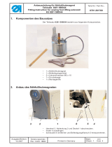
Der Bausatz Lichtschranke - Teile Nr. 0806 490010 ist für Nähanlagen der Klasse 806 vorgesehen.
2 Inhalt des Teilesatzes
Lichtschranke für Transferplatte
Lichtschranke für
automatisches Vakuum
Lichtschranke für Ausroller
Der Nachrüstsatz besteht aus folgenden Bauteilen:
Menge Bezeichnung Material-Nr.
1 Lichtschranke 9815 920036
1 Winkel für Transferplatte 0806 405150
1 Adapterplatte für Ausroller 0745 561210
1 Halter für automatisches Vakuum 9815 920039
2 Linsenschraube M3 x 6-H 9204 201047
2 Linsenschraube M3 x 14 9203 003087
2 Unterlegscheibe 9330 000067
5 Kabelbinder 9840 121001
Bausatz Lichtschranke 0806 490010
Kit Light Barrier 0806 490010
Teile-Nr./ Part-No.:
0791 806700
Blatt: von
Sheet: 1 from 8
Ausgabe/Edition:
05.2010
Änderungsindex
Rev. index: 00.0
Printed in Germany

3 Nachrüstsatz montieren
3.1 Lichtschranke für Transferplatte
– Abdeckung 1 entfernen.
– Lichtschranke 2 mit den beiden Linsenschrauben M3 x 14 und zwei Unterlegscheiben auf den
Winkel 3 schrauben.
– Winkel 3 mit der Lichtschranke am Gestell 5 anschrauben (mit vorhandenen Schrauben 4).
– Druckluftschlauch 6 mit einem Kabelbinder 7 an der Leitung der Lichtschranke befestigen.
3.2 Lichtschranke für Ausroller
–
Lichtschranke 1 mit den beiden Schrauben M3 x 14 und Unterlegscheiben auf die Adapterplatte 2
schrauben.
–
Lichtschranke mit Adapterplatte 2 mit den beiden Schrauben M3 x 6 im Ausrollerarm befestigen.
Bausatz Lichtschranke 0806 490010
Kit Light Barrier 0806 490010
Teile-Nr./ Part-No.:
0791 806700
Blatt: von
Sheet: 2 from 8
Ausgabe/Edition:
05.2010
Änderungsindex
Rev. index: 00.0
Printed in Germany
1
2
3
6
7
M3 x 6
M3 x 14
1
2
2
4
M3 x 14
5

3.3 Lichtschranke für Vakuum
Gewinde M3
– Im Halter 1 zwei Gewinde M3 anbringen (Maße siehe Skizze).
– Lichtschranke 2 mit den beiden Schrauben M3 x 14 und den beiden Scheiben auf den Winkel 3
schrauben.
– Winkel 1 am Bügel 4 befestigen und ausrichten.
3.4 Elektrischer Anschluß nach Schaltplan 9870 806020 B (siehe Teileliste)
–
Transferplattenidentifizierung (S34) / Blatt 7 Klemmleiste X21 (Verteiler im Gestell)
–
Ausroller (S30) / Blatt 11 Klemmleiste X46
–
autom. Vakuum (S4) / Blatt 8 Klemmleiste X27 (im Umbugstation)
ALT:
Lichtschranke RK404K/P
9815 920012
Aderfarben
NEU:
Lichtschranke RKR3B/66.1
9815 920036 im Bausatz
0806 490010
+24V braun +24V
0V (GND) blau 0V (GND)
OUT schwarz OUT
weiß
Sicher isolieren und Kurzschluß zu
anderen Drähten/Klemmen
ausschließen!
Bausatz Lichtschranke 0806 490010
Kit Light Barrier 0806 490010
Teile-Nr./ Part-No.:
0791 806700
Blatt: von
Sheet: 3 from 8
Ausgabe/Edition:
05.2010
Änderungsindex
Rev. index: 00.0
Printed in Germany
1
43 21

3.5 Einstellung der Reichweite
Empfindlichkeit der Lichtschranke ändern durch
verstellen des Potentiometers.
Linke Anschlag: kleinste Empfindlichkeit
kürzeste Reichweite
Rechte Anschlag: größte Empfindlichkeit
größte Reichweite
Bausatz Lichtschranke 0806 490010
Kit Light Barrier 0806 490010
Teile-Nr./ Part-No.:
0791 806700
Blatt: von
Sheet: 4 from 8
Ausgabe/Edition:
05.2010
Änderungsindex
Rev. index: 00.0
Printed in Germany

1 Use of the kit
The kit light barrier – Part No. 0806 490010 is intended to be used with class 806 sewing units.
2 Kit Components
Light barrier for transfer plate
Light barrier for
automatic vacuum
Light barrier for roll-out device
The retrofit kit consists of the following components:
Quantity Designation Material-No.
1 Light barrier 9815 920036
1 Bracket for transfer plate 0806 405150
1 Adapter plate for roll-out device 0745 561210
1 Holder for the automatic vacuum 9815 920039
2 Fillister head screws M3 x 6-H 9204 201047
2 Fillister head screws M3 x 14 9203 003087
2 Washer 9330 000067
5 Cable ties 9840 121001
Bausatz Lichtschranke 0806 490010
Kit Light Barrier 0806 490010
Teile-Nr./ Part-No.:
0791 806700
Blatt: von
Sheet: 5 from 8
Ausgabe/Edition:
05.2010
Änderungsindex
Rev. index: 00.0
Printed in Germany

3 Mounting the kit
3.1 Light barrier for transfer plate
– Remove the cover 1.
– Screw the light barrier 2 on the bracket 3 using the fillister head screws M3 x 14 and two washers.
– Screw the bracket 3 with the light barrier on the frame 5 (with the original screws 4).
– Fix the compressed air hose 6 to the light barrier cable using the cable tie 7.
3.2 Light barrier for roll-out device
–
Screw the light barrier 1 on the adapter plate 2 using the fillister head screws M3 x 14 and two
washers.
–
Fix the light barrier with the adapter plate 2 to the arm of the roll-out device using both fillister
head screws M3 x 6.
Bausatz Lichtschranke 0806 490010
Kit Light Barrier 0806 490010
Teile-Nr./ Part-No.:
0791 806700
Blatt: von
Sheet: 6 from 8
Ausgabe/Edition:
05.2010
Änderungsindex
Rev. index: 00.0
Printed in Germany
1
2
3
6
7
M3 x 6
M3 x 14
1
2
2
4
M3 x 14
5

3.3 Light barrier for the vacuum
M3 thread
– Tap two threaded holes (M3) in the holder 1 (Measures see sketch).
– Screw the light barrier 2 on the bracket 3 using both fillister head screws M3 x 14 and two
washers.
– Fix the bracket 1 to the bow 4 and align it.
3.4 Electrical connection according to circuit diagram 9870 806020 B (see parts list)
–
Identification of the transfer plate (S34) / Sheet 7 Terminal strip X21 (distribution box in the frame)
–
Roll-out device (S30) / Sheet 11 Terminal strip X46
–
Automatic vacuum (S4) / Sheet 8 Terminal strip X27 (in the folding station)
OLD:
Light barrier RK404K/P
9815 920012
Wire colors
NEW:
Light barrier RKR3B/66.1
9815 920036 in the kit 0806 490010
+24V brown +24V
0V (GND) blue 0V (GND)
OUT black OUT
white
Isolate properly and prevent from
causing a short circuit with other
wires or terminals!
Bausatz Lichtschranke 0806 490010
Kit Light Barrier 0806 490010
Teile-Nr./ Part-No.:
0791 806700
Blatt: von
Sheet: 7 from 8
Ausgabe/Edition:
05.2010
Änderungsindex
Rev. index: 00.0
Printed in Germany
1
43 21

3.5 Setting the range
Change the sensitivity of the light barrier by adjusting
the potentiometer.
To the left: least sensitivity
shortest range
To the right: greatest sensitivity
highest range
Bausatz Lichtschranke 0806 490010
Kit Light Barrier 0806 490010
Teile-Nr./ Part-No.:
0791 806700
Blatt: von
Sheet: 8 from 8
Ausgabe/Edition:
05.2010
Änderungsindex
Rev. index: 00.0
Printed in Germany
/
