Page is loading ...

Ausgabe/Edition:
05.2010
Änderungsindex
Rev. index: 00.0
Printed in Germany
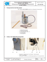
1 Komponenten des Teilesatzes
Der Teilesatz besteht aus folgenden Bauteilen:
Menge Material-Nr. Bezeichnung
1 0510 491010 Bügel (10mm Rundstahl 90° gebogen)
1 0911 490240 Winkel
3 9202 002487 Zylinderschr. M5 x 12 (2x Winkel an Kopfdeckel/1x Bügel
an Winkel)
1 0911 490260 Platte (für die Leiterplatten)
2 9203 313697 Senkschr. M4 x 16 (Bef. der Platte anstelle der Leiterpl.)
2 0739 005010 Hülse (Bef. der Platte anstelle der Leiterpl.)
4 9202 002087 Zylinderschr. M4 x 12 (zusätzl. Abstützung f. die Platte)
4 9231 110057 6kt.Mutter M4 (zusätzl. Abstützung f. die Platte)
4 9830 501010 Distanzhalter, PA4,8 (für die kl.Leiterpl., die auf die Platte
umgesetzt wird)
1 9870 911015 Leitung komplett
6 9840 121002 Kabelbinder 200 x 2,5
2 Zusätzlich erforderliche Teilesätze
2.1 Laserleuchte mit Netzteil (Material-Nr. 0911 597534)
Dieser Teilesatz muss mind. 1x - max. 4x mitbestellt werden.
Der Teilesatz besteht aus folgenden Bauteilen:
Menge Bezeichnung Material-Nr.
1 9835 501004 Laser komplett
1 0806 402670 Klemmstück (auf Bügel 0510 491010)
1 0806 402680 Klemmstück (in Klemmstück 0806 402670)
3 0216 000103 6kt.Mutter M10x1 (1x Klemmstück 1 auf Bügel klemmen;
1x Klemmstück 2 in Klemmstück 1 klemmen; 1x Laser in
Klemmstück 2 klemmen)
1 9850 001090 Leiterplatte komplett, Lasernetzteil
4 9830 501010 Distanzhalter, PA4,8
2 9840 121001 Kabelbinder 200 x 2,5
Anbauanleitung für Laserleuchte
Teilesatz 0911 597524
Fitting Instruction for laser lamp
Kit 0911 597524
Teile-Nr./ Part-No.:
0791 911701
Blatt: von
Sheet: 1 from 16

2.2 Bausatz 0510 590034 “Laser-Erg.Leuchte komplett”
Pro Netzteil können optional noch bis zu 2 weitere Laserleuchten
angeschlossen werden. Alle drei Laserleuchten weden dann als
Gruppe geschaltet werden.
Hierfür gibt es den Bausatz 0510 590034 “Laser-Erg.Leuchte
komplett”
Der Teilesatz besteht aus folgenden Bauteilen:
Menge Bezeichnung Material-Nr.
1 9835 501004 Laser komplett
1 0806 402670 Klemmstück (auf Bügel 0510 491010)
1 0806 402680 Klemmstück (in Klemmstück 0806 402670)
3 0216 000103 6kt.Mutter M10 x 1 (1x Klemmstück 1 auf Bügel klemmen;
1x Klemmstück 2 in Klemmstück 1 klemmen;
1x Laser in Klemmstück 2 klemmen)
3 Teilesatz montieren
Vorsicht Verletzungsgefahr!
Hauptschalter ausschalten.
Teilesatz nur bei ausgeschalteter Nähanlage montieren.
3.1 Platte für die Netzteile montieren
–
Abdeckung 1 und 2 abschrauben.
–
Leiterplatte 3 von Platte 4 abschrauben.
Anbauanleitung für Laserleuchte
Teilesatz 0911 597524
Fitting Instruction for laser lamp
Kit 0911 597524
Teile-Nr./ Part-No.:
0791 911701
Blatt: von
Sheet: 2 from 16
Ausgabe/Edition:
05.2010
Änderungsindex
Rev. index: 00.0
Printed in Germany
21 43

–
Platte 5 für die Leiterplatten mit zwei Senkschrauben M4x16
und den zwei Befestigungshülsen auf Platte 4 schrauben.
– Distanzhalter 6 pro Netzteil in die Bohrungen der Platte 5
drücken.
Je vier pro Netzteil.
– Leiterplatte 3 ebenfalls mit Distanzhaltern drücken.
3.2 Netzteil montieren und Zuleitung anschließen
–
Netzteil(e) 7 auf Distanzhalter drücken.
–
Leitung 8 für die Spannungsversorgung an den Eingang X1 des
Netzteils 7 anschließen.
Anbauanleitung für Laserleuchte
Teilesatz 0911 597524
Fitting Instruction for laser lamp
Kit 0911 597524
Teile-Nr./ Part-No.:
0791 911701
Blatt: von
Sheet: 3 from 16
Ausgabe/Edition:
05.2010
Änderungsindex
Rev. index: 00.0
Printed in Germany
54
63
87

3.3 Zuleitung zur Steuerung verlegen und anschließen
– Zuleitung 1 (wie auf den Abbildungen zu sehen) unter die
Tischplatte verlegen.
– Zuleitung 1 mit Kabelbindern am Kabelstrang 2 festbinden.
–
Stecker 3 der Zuleitung in die Dose X100t an der Steuerung
stecken und mit den beiden Schrauben sichern.
Anbauanleitung für Laserleuchte
Teilesatz 0911 597524
Fitting Instruction for laser lamp
Kit 0911 597524
Teile-Nr./ Part-No.:
0791 911701
Blatt: von
Sheet: 4 from 16
Ausgabe/Edition:
05.2010
Änderungsindex
Rev. index: 00.0
Printed in Germany
1
21
3

3.4 Kopfdeckel vorbereiten
Im Teilesatz befindet sich kein neuer Kopfdeckel.
Es müssen 2 Löcher in den vorhandenen Kopfdeckel gebohrt
werden.
Siehe dazu Zeichnung auf Seite 8.
– Kopfdeckel 1 abschrauben.
– Löcher 2 nach Zeichnung in den Kopdeckel bohren.
Anbauanleitung für Laserleuchte
Teilesatz 0911 597524
Fitting Instruction for laser lamp
Kit 0911 597524
Teile-Nr./ Part-No.:
0791 911701
Blatt: von
Sheet: 5 from 16
Ausgabe/Edition:
05.2010
Änderungsindex
Rev. index: 00.0
Printed in Germany
1
2

3.5 Laserleuchte(n) und Halterung montieren
– Bügel 1 an den Winkel 2 montieren.
– Winkel2mitzweiSchraubenM5x12voninnenam
Kopfdeckel 3 befestigen.
– Kopfdeckel montieren.
– Laserleuchte(n) mit Klemmstücken 5 am Bügel 2 befestigen.
– Leitungen der Laserleuchte(n) mit Kabelbindern am Bügel 2
sichern.
– Leitungen 6 wie auf der Abbildung zu sehen zu den Netzteilen
verlegen.
–
Die beiden Adern 8 der Laserleuchtenleitung am
Steckkontakt 7 (Ausgang X2) anschließen.
Anbauanleitung für Laserleuchte
Teilesatz 0911 597524
Fitting Instruction for laser lamp
Kit 0911 597524
Teile-Nr./ Part-No.:
0791 911701
Blatt: von
Sheet: 6 from 16
Ausgabe/Edition:
05.2010
Änderungsindex
Rev. index: 00.0
Printed in Germany
32 1
54 2
87
6

4 Aktivierung der Laserleuchten
–
Nähanlage einschalten und den Einschaltvorgang durchführen.
–
Im Hauptbildschirm:
Bearbeiten ÚNahtprogramm Ú Parameter auswählen.
Es erscheint folgender Bildschirm:
– Icon “Laserlampen” auswählen.
Es erscheint folgender Bildschirm:
–
Entsprechende Laserlampen durch Auswahl aktivieren.
–
Taste “OK” drücken.
Die Einstellungen werden übernommen.
Anbauanleitung für Laserleuchte
Teilesatz 0911 597524
Fitting Instruction for laser lamp
Kit 0911 597524
Teile-Nr./ Part-No.:
0791 911701
Blatt: von
Sheet: 7 from 16
Ausgabe/Edition:
05.2010
Änderungsindex
Rev. index: 00.0
Printed in Germany

Anbauanleitung für Laserleuchte
Teilesatz 0911 597524
Fitting Instruction for laser lamp
Kit 0911 597524
Teile-Nr./ Part-No.:
0791 911701
Blatt: von
Sheet: 8 from 16
Ausgabe/Edition:
05.2010
Änderungsindex
Rev. index: 00.0
Printed in Germany

Ausgabe/Edition:
05.2010
Änderungsindex
Rev. index: 00.0
Printed in Germany
1 Kit Components
The kit consists of the following components:
Quantity Material-No. Designation
1 0510 491010 Bow (10mm Round steel bent 90°)
1 0911 490240 L-bracket
3 9202 002487 Cylinder head screw M5 x 12 (2x L-bracket on face cover,
1x bow on L-bracket)
1 0911 490260 Plate (for the PCBs)
2 9203 313697 Countersunk screw M4 x 16 (Fixation of the plate instead
of the PCB)
2 0739 005010 Sleeve (Fixation of the board instead of the PCB)
4 9202 002087 Cylinder head screw M4 x 12 (additional support for the plate)
4 9231 110057 Hexagonal nut M4 (additional support for the board)
4 9830 501010 Distance piece, PA4.8 (for the small PCB that is repositioned
on the plate)
1 9870 911015 Cable
6 9840 121002 Cable tie 200 x 2.5
2 Additionally needed kits
2.1 Laser lamp with power supply unit (Material-No. 0911 597534)
This kit must be ordered at least 1x up to max. 4 times.
The kit consists of the following components:
Quantity Material-No. Designation
1 9835 501004 Laser complete
1 0806 402670 Clamp (on bow 0510 491010)
1 0806 402680 Clamp (in clamp 0806 402670)
3 0216 000103 Hexagonal nut M10 x 1 (1x lock clamp 1 on bow;
1x lock clamp 2 on clamp 1; 1x lock laser
on clamp 2)
1 9850 001090 PCB complete, Laser power supply unit
4 9830 501010 Distance piece, PA4.8
2 9840 121001 Cable tie 200 x 2.5
Anbauanleitung für Laserleuchte
Teilesatz 0911 597524
Fitting Instruction for laser lamp
Kit 0911 597524
Teile-Nr./ Part-No.:
0791 911701
Blatt: von
Sheet: 9 from 16

2.2 Kit 0510 590034 “Laser additional lamp complete”
With each power supply unit up to 2 additional laser lamps can be
connected. The three laser lamps are then connected as a group.
To this end the kit 0510 590034 “Laser additional lamp complete”
is available.
The kit consists of the following components:
Quantity Material-No. Designation
1 9835 501004 Laser complete
1 0806 402670 Clamp (on bow 0510 491010)
1 0806 402680 Clamp (in clamp 0806 402670)
3 0216 000103 Hexagonal nut M10 x 1 (1x lock clamp 1 on bow;
1x lock clamp 2 on clamp 1; 1x lock laser
on clamp 2).
3 Mounting the kit
Caution: Risk of injury!
Turn the main switch off!
Mount the kit only with the sewing unit switched off!
3.1 Mounting the plate for the power supply units
–
Unscrew the cover 1 and 2.
–
Unscrew the PCB 3 from the plate 4.
Anbauanleitung für Laserleuchte
Teilesatz 0911 597524
Fitting Instruction for laser lamp
Kit 0911 597524
Teile-Nr./ Part-No.:
0791 911701
Blatt: von
Sheet: 10 from 16
Ausgabe/Edition:
05.2010
Änderungsindex
Rev. index: 00.0
Printed in Germany
21 43

–
Screw the plate 5 for the PCBs using two countersunk screws
M4 x 16 and the two fixation sleeves onto the plate 4.
– Push for each power supply unit 4 distance pieces 6 into the
bore holes on plate 5.
– Press the PCB 3 also with distance pieces onto the plate 5.
3.2 Mounting the power supply unit and the cord
–
Press the power supply unit(s) 7 onto the distance pieces.
–
Connect the cord 8 for the power supply to the input X1 of the
power supply unit 7.
Anbauanleitung für Laserleuchte
Teilesatz 0911 597524
Fitting Instruction for laser lamp
Kit 0911 597524
Teile-Nr./ Part-No.:
0791 911701
Blatt: von
Sheet: 11 from 16
Ausgabe/Edition:
05.2010
Änderungsindex
Rev. index: 00.0
Printed in Germany
54
63
87

3.3 Wiring and connecting the cable to the control unit
– Run the cable 1 (as shown on the pictures) beneath the table
plate.
– Fix the cable 1 with cable ties onto the wiring harness 2.
–
Plug the plug 3 of the cable into the socket X100t on the
control unit and fix it with the two screws.
Anbauanleitung für Laserleuchte
Teilesatz 0911 597524
Fitting Instruction for laser lamp
Kit 0911 597524
Teile-Nr./ Part-No.:
0791 911701
Blatt: von
Sheet: 12 from 16
Ausgabe/Edition:
05.2010
Änderungsindex
Rev. index: 00.0
Printed in Germany
1
21
3

3.4 Preparing the face cover
The kit does not include a new face cover.
Two new holes need to be drilled into the existing face cover.
To this end see the drawing on page 8.
– Unscrew the face cover 1.
– Drill the holes 2 according to the drawing into the face cover.
Anbauanleitung für Laserleuchte
Teilesatz 0911 597524
Fitting Instruction for laser lamp
Kit 0911 597524
Teile-Nr./ Part-No.:
0791 911701
Blatt: von
Sheet: 13 from 16
Ausgabe/Edition:
05.2010
Änderungsindex
Rev. index: 00.0
Printed in Germany
1
2

3.5 Mounting the laser lamps(s) and the holder
– Fix the bow 1 onto the L-bracket 2.
– Fix the L-bracket 2 using two screws M5 x 12 from the inside of
the cover face 3.
– Mount the face cover
– Fix the laser lamps(s) with the clamps 5 onto the bow 2.
– Fix the cables of the laser lamps(s) with cable ties onto bow 2.
– Run the cables 6 as shown in the pictures to the power supply
units.
–
Connect the two wires 8 of the laser lamp cable to the socket 7
(output X2).
Anbauanleitung für Laserleuchte
Teilesatz 0911 597524
Fitting Instruction for laser lamp
Kit 0911 597524
Teile-Nr./ Part-No.:
0791 911701
Blatt: von
Sheet: 14 from 16
Ausgabe/Edition:
05.2010
Änderungsindex
Rev. index: 00.0
Printed in Germany
32 1
54 2
87
6

4 Activating the laser lamps
–
Switch on the sewing unit and effectuate the switching on
procedure.
–
Select on the main screen:
EditÚSeam programÚParameters
The following screen appears:
– Select the icon “Laser lamps”.
The following screen will appear:
–
Activate the corresponding laser lamp by selecting it.
–
Press the “OK” button .
The settings are adopted.
Anbauanleitung für Laserleuchte
Teilesatz 0911 597524
Fitting Instruction for laser lamp
Kit 0911 597524
Teile-Nr./ Part-No.:
0791 911701
Blatt: von
Sheet: 15 from 16
Ausgabe/Edition:
05.2010
Änderungsindex
Rev. index: 00.0
Printed in Germany

Anbauanleitung für Laserleuchte
Teilesatz 0911 597524
Fitting Instruction for laser lamp
Kit 0911 597524
Teile-Nr./ Part-No.:
0791 911701
Blatt: von
Sheet: 16 from 16
Ausgabe/Edition:
05.2010
Änderungsindex
Rev. index: 00.0
Printed in Germany
/