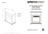
Shown with optional
cabinet mantel,
hearth base, and trim
accessories.
Save this manual for future reference.
WARNING: If the information in this manual is not
followed exactly, a fire or explosion may result caus-
ing property damage, personal injury, or loss of life.
— Do not store or use gasoline or other
flammable vapors and liquids in the vicinity of
this or any other appliance.
— WHAT TO DO IF YOU SMELL GAS
• Do not try to light any appliance.
• Do not touch any electrical switch; do not
use any phone in your building.
• Immediately call your gas supplier from a
neighbor’s phone. Follow the gas
supplier’s instructions.
• If you cannot reach your gas supplier, call
the fire department.
— Installation and service must be performed by
a qualified installer, service agency, or the gas
supplier.
WARNING: Improper installa-
tion, adjustment, alteration, ser-
vice, or maintenance can cause
injury or property damage. Re-
fer to this manual for correct
installation and operational pro-
cedures. For assistance or ad-
ditional information consult a
qualified installer, service
agency, or the gas supplier.
OWNER’S OPERATION AND INSTALLATION MANUAL
UNVENTED (VENT-FREE)
CATALYTIC NATURAL GAS
FIREPLACE
VCGF30NR
REMOTE READY
CATALYTIC
GAS FIREPLACE
SYSTEM
This appliance may be installed in an aftermarket*, permanently located, manufac-
tured (mobile) home, where not prohibited by local codes.
This appliance is only for use with the type of gas indicated on the rating plate.
This appliance is not convertible for use with other gases.
* Aftermarket: Completion of sale, not for purpose of resale, from the manufacturer
Patent Pending
WARNING: This is an unvented
gas-fired heater. It uses air (oxy-
gen) from the room in which it is
installed. Provisions for adequate
combustion and ventilation air
must be provided. Refer to
Air for
Combustion and Ventilation
sec-
tion on page 4 of this manual.
®

2
104636
UNVENTED NATURAL GAS FIREPLACE
®
SAFETY
INFORMATION
DANGER: Carbon monoxide
poisoning may lead to death!
Carbon Monoxide Poisoning: Early signs
of carbon monoxide poisoning resemble the
flu, with headaches, dizziness, or nausea. If
you have these signs, the fireplace may not
be working properly. Get fresh air at once!
Have fireplace serviced. Some people are
more affected by carbon monoxide than
others. These include pregnant women,
people with heart or lung disease or anemia,
those under the influence of alcohol, and
those at high altitudes.
Natural Gas: Natural gas is odorless. An
odor-making agent is added to the gas. The
odor helps you detect a gas leak. However,
the odor added to the gas can fade. Gas may
be present even though no odor exists.
Make certain you read and understand all
Warnings. Keep this manual for reference.
It is your guide to safe and proper operation
of this fireplace.
WARNINGS
IMPORTANT: Read this owner’s
manual carefully and completely
before trying to assemble, operate,
or service this fireplace. Improper
use of this fireplace can cause seri-
ous injury or death from burns, fire,
explosion, electrical shock, and
carbon monoxide poisoning.
1. This appliance is only for use with the
type of gas indicated on the rating plate.
This appliance is not convertible for use
with other gases.
2. If you smell gas
• shut off gas supply
• do not try to light any appliance
•
do not touch any electrical switch; do
not use any phone in your building
• immediately call your gas supplier
from a neighbor’s phone. Follow the
gas supplier’s instructions
• if you cannot reach your gas supplier,
call the fire department
3. This fireplace shall not be installed in
a bedroom or bathroom.
4. Do not use this fireplace as a wood-
burning fireplace. Use only the logs
provided with the fireplace.
5. Do not add extra logs or ornaments
such as pine cones, vermiculite, or rock
wool. Using these added items can
cause sooting. Do not add lava rock
around base. Rock and debris could fall
into the control area of fireplace.
6. This fireplace is designed to be smoke-
less. If logs ever appear to smoke, turn
off fireplace and call a qualified ser-
vice person.
Note:
During initial op-
eration, slight smoking could occur due
to log curing and fireplace burning
manufacturing residues.
7. To prevent the creation of soot, follow
the instructions in Cleaning and Main-
tenance, page 21.
8. Before using furniture polish, wax, car-
pet cleaner, or similar products, turn
heater off. If heated, the vapors from
these products may create a white pow-
der residue within burner box or on
adjacent walls or furniture.
9. This fireplace needs fresh air ventila-
tion to run properly. This fireplace has
an Oxygen Depletion Sensing (ODS)
safety shutoff system. The ODS shuts
down the fireplace if not enough fresh
air is available. See Air for Combus-
tion and Ventilation, pages 4 through
6. If fireplace keeps shutting off, see
Troubleshooting, pages 17 through 19.
10. Do not run fireplace
• where flammable liquids or vapors
are used or stored
• under dusty conditions
11. Do not use this fireplace to cook food
or burn paper or other objects.
12. Do not use fireplace if any part has been
exposed to or under water. Immediately
call a qualified service technician to
inspect the fireplace and to replace any
part of the control system and any gas
control which has been under water.
13. Do not operate fireplace if any log is
broken. Do not operate fireplace if a
log is chipped (dime-sized or larger).
14. Turn fireplace off and let cool before
servicing. Only a qualified service per-
son should service and repair fireplace.
15. Operating fireplace above elevations of
4,500 feet could cause pilot outage.
WARNING: Any change to
this heater or its controls can be
dangerous.
WARNING: Do not allow fans
to blow directly into the fireplace.
Avoid any drafts that alter burner
flame patterns. Ceiling fans can
create drafts that alter burner
flame patterns. Altered burner
patterns can cause sooting.
WARNING: Do not use a
blower insert, heat exchanger
insert or other accessory not ap-
proved for use with this fireplace.
Due to high temperatures, the
appliance should be located out
of traffic and away from furniture
and draperies.
Do not place clothing or other
flammable material on or near
the appliance. Never place any
objects on the heater.
Fireplace front becomes very hot
when running fireplace. Keep
children and adults away from
hot surfaces to avoid burns or
clothing ignition. Fireplace will
remain hot for a time after shut-
down. Allow surfaces to cool be-
fore touching.
Carefully supervise young chil-
dren when they are in the room
with fireplace. When using the
hand-held remote accessory,
keep selector switch in the OFF
position to prevent children from
turning on burners with remote.
You must operate this fireplace
with the front window assembly
and hood in place. Make sure front
window assembly and hood are in
place before running fireplace.
Keep the appliance area clear and
free from combustible materials,
gasoline, and other flammable
vapors and liquids.

3
104636
OWNER’S MANUAL
AUTO
ON
OFF
COOLER
WARMER
TEMP
O
F
F
P
I
L
O
T
O
N
H
I
L
O
PRODUCT
IDENTIFICATION
LOCAL CODES
Install and use fireplace with care. Follow all
local codes. In the absence of local codes, use
the latest edition of The National Fuel Gas
Code ANS Z223.1, also known as NFPA 54*.
*Available from:
American National Standards Institute, Inc.
1430 Broadway
New York, NY 10018
National Fire Protection Association, Inc.
Batterymarch Park
Quincy, MA 02269
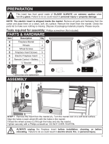
UNPACKING
1. With utility knife, cut the carton all the
way around above the staples on the
bottom tray. Lift the carton off the
heater. Remove packing.
Note:
The
hood is located in the packing on the
right hand side of the heater front. Lift
the heater off the bottom tray.
2. Locate two phillips-head screws at top
corners of front window assembly. Re-
move and save these screws. Carefully
lift front window assembly up and out
from fireplace front.
3. Remove protective packaging applied to
logs, log base assembly, and fireplace.
4. Remove fireplace hood from carton
insert.
5. Check all items for any shipping dam-
age. If damaged, promptly inform
dealer where you bought fireplace.
Figure 1 - Log Base Assembly
One Piece Log Set
Figure 2 - Fireplace
Top Louver
Assembly
Firebox
Hood
Front
Window
Assembly
Top Outer
Casing
Firebox
Support
Blower Assembly
(Optional)
Optional
Remote
Control
REMOTE CONTROL
ACCESSORIES
There are four optional remote controls that
can be purchased separately for this log
heater:
• wall switch
• wall thermostat
• hand-held ON/OFF remote
• hand-held thermostat remote
See Accessories, pages 22 and 23.
Bottom Louver
Assembly
Catalytic
Filter
(Mounted To
Inside
Firebox Top)
CAUTION: Do not remove the
metal data plates from the heater
base assembly. The data plates
contain important product
information.
Selector Switch
(Optional)
Piezo
Ignitor
Control
Knobs

4
104636
UNVENTED NATURAL GAS FIREPLACE
®
AIR FOR
COMBUSTION AND
VENTILATION
Today’s homes are built more energy effi-
cient than ever. New materials, increased
insulation, and new construction methods
help reduce heat loss in homes. Home owners
weather strip and caulk around windows and
doors to keep the cold air out and the warm air
in. During heating months, home owners
want their homes as airtight as possible.
While it is good to make your home energy
efficient, your home needs to breathe. Fresh
air must enter your home. All fuel-burning
appliances need fresh air for proper com-
bustion and ventilation.
Exhaust fans, fireplaces, clothes dryers, and
fuel burning appliances draw air from the house
to operate. You must provide adequate fresh air
for these appliances. This will insure proper
venting of vented fuel-burning appliances.
PROVIDING ADEQUATE
VENTILATION
The following are excerpts from National
Fuel Gas Code, NFPA 54/ANS Z223.1, Sec-
tion 5.3, Air for Combustion and Ventilation.
All spaces in homes fall into one of the three
following ventilation classifications:
1. Unusually Tight Construction
2. Unconfined Space
3. Confined Space
The information on pages 4 through 6 will
help you classify your space and provide
adequate ventilation.
Unusually Tight Construction
The air that leaks around doors and win-
dows may provide enough fresh air for
combustion and ventilation. However, in
Confined Space and Unconfined
Space
The National Fuel Gas Code ANS Z223.1
defines a confined space as a space whose
volume is less than 50 cubic feet per 1,000
Btu per hour (4.8 m
3
per kw) of the aggre-
gate input rating of all appliances installed
in that space and an unconfined space as a
space whose volume is not less than 50
cubic feet per 1,000 Btu per hour (4.8 m
3
per
kw) of the aggregate input rating of all
appliances installed in that space. Rooms
communicating directly with the space in
which the appliances are installed*, through
openings not furnished with doors, are con-
sidered a part of the unconfined space.
This heater shall not be installed in a con-
fined space or unusually tight construction
unless provisions are provided for adequate
combustion and ventilation air.
* Adjoining rooms are communicating only
if there are doorless passageways or ventila-
tion grills between them.
PRODUCT
FEATURES
OPERATION
This vent-free fireplace is clean burning. It
requires no outside venting. There is no heat
loss out a vent or up a chimney. Heat is
generated by both realistic flames and glow-
ing embers. When used without the blower,
the fireplace requires no electricity making
it ideal for emergency backup heat.
CATALYTIC TECHNOLOGY
This fireplace incorporates a catalytic sys-
tem. It features a unique steel spiral coil filter
with a precious metal coating which lowers
combustion by-products by reburning them.
SAFETY DEVICE
This fireplace has a pilot with an Oxygen
Depletion Sensing (ODS) safety shutoff sys-
tem. The ODS/pilot is a required feature for
vent-free room heaters. The ODS system
shuts off the fireplace if there is not enough
fresh air.
PIEZO IGNITION SYSTEM
This fireplace has a piezo ignitor. This sys-
tem requires no matches, batteries, or other
sources to light fireplace.
BLOWER ASSEMBLY
(GA3700 and GA3700T Series)
This fireplace accepts an optional blower
assembly. The GA3700T series blower op-
erates thermostatically and features vari-
able speed control. The GA3700 series
blower also features variable speed control.
The blower circulates heated air from the
fireplace into the room. Use of blower is
optional. See Accessories, pages 22 and 23.
WARNING: This heater shall
not be installed in a confined space
or unusually tight construction
unless provisions are provided
for adequate combustion and ven-
tilation air. Read the following in-
structions to insure proper fresh
air for this and other fuel-burning
appliances in your home.
buildings of unusually tight construction,
you must provide additional fresh air.
Unusually tight construction is de-
fined as construction where:
a. walls and ceilings exposed to the
outside atmosphere have a con-
tinuous water vapor retarder with
a rating of one perm (6 x 10
-11
kg
per pa-sec-m
2
) or less with open-
ings gasketed or sealed
and
b. weather stripping has been
added on openable windows and
doors
and
c. caulking or sealants are applied
to areas such as joints around
window and door frames, be-
tween sole plates and floors, be-
tween wall-ceiling joints, be-
tween wall panels, at penetra-
tions for plumbing, electrical, and
gas lines, and at other openings.
If your home meets all of the three
criteria above, you must provide ad-
ditional fresh air. See
Ventilation Air
From Outdoors
, page 6
.
If your home does not meet all of the
three criteria above, proceed to
Deter-
mining Fresh-Air Flow for Fireplace
Location
on page 5.

5
104636
OWNER’S MANUAL
AIR FOR
COMBUSTION AND
VENTILATION
Continued
DETERMINING FRESH-AIR FLOW FOR FIREPLACE LOCATION
Determining if You Have a Confined or Unconfined Space
Use this work sheet to determine if you have a confined or unconfined space.
Space: Includes the room in which you will install fireplace plus any adjoining rooms with doorless passageways or ventilation grills
between the rooms.
1. Determine the volume of the space (length x width x height).
Length x Width x Height = _________________cu. ft. (volume of space)
Example:
Space size 22 ft. (length) x 18 ft. (width) x 8 ft. (ceiling height) = 3168 cu. ft. (volume of space)
If additional ventilation to adjoining room is supplied with grills or openings, add the volume of these rooms to the total volume of
the space.
2. Divide the space volume by 50 cubic feet to determine the maximum Btu/Hr the space can support.
_________________ (volume of space) ÷ 50 cu. ft. = (Maximum Btu/Hr the space can support)
Example:
3168 cu. ft. (volume of space) ÷ 50 cu. ft. = 63.3 or 63,300 (maximum Btu/Hr the space can support)
3. Add the Btu/Hr of all fuel burning appliances in the space.
Vent-free fireplace ___________________ Btu/Hr
Gas water heater* ___________________ Btu/Hr
Gas furnace ___________________ Btu/Hr
Vented gas heater ___________________ Btu/Hr
Gas fireplace logs ___________________ Btu/Hr
Other gas appliances* + ___________________ Btu/Hr
Total = ___________________ Btu/Hr
* Do not include direct-vent gas appliances. Direct-vent draws combustion air from the outdoors and vents to the outdoors.
4. Compare the maximum Btu/Hr the space can support with the actual amount of Btu/Hr used.
_____________ Btu/Hr (maximum the space can support)
_____________ Btu/Hr (actual amount of Btu/Hr used)
Example:
63,300 Btu/Hr (maximum the space can support)
70,000 Btu/Hr (actual amount of Btu/Hr used)
The space in the above example is a confined space because the actual Btu/Hr used is more than the maximum Btu/Hr the space can support.
You must provide additional fresh air. Your options are as follows:
A. Rework work sheet, adding the space of an adjoining room. If the extra space provides an unconfined space, remove door to adjoin-
ing room or add ventilation grills between rooms. See Ventilation Air from Inside Building, page 6.
B. Vent room directly to the outdoors. See Ventilation Air from Outdoors, page 6.
C. Install a lower Btu/Hr fireplace, if lower Btu/Hr size makes room unconfined.
If the actual Btu/Hr used is less than the maximum Btu/Hr the space can support, the space is an unconfined space. You will need no
additional fresh air ventilation.
Continued
Example:
Gas water heater
40,000
Btu/Hr
Vent-free fireplace +
30,000
Btu/Hr
Total =
70,000
Btu/Hr
WARNING: If the area in which the heater may be operated is smaller than that defined as an unconfined space
or if the building is of unusually tight construction, provide adequate combustion and ventilation air by one of
the methods described in the
National Fuel Gas Code, ANS Z223.1, Section 5.3
or applicable local codes.

6
104636
UNVENTED NATURAL GAS FIREPLACE
®
AIR FOR
COMBUSTION AND
VENTILATION
Continued
VENTILATION AIR
Ventilation Air From Inside
Building
This fresh air would come from an adjoining
unconfined space. When ventilating to an
adjoining unconfined space, you must pro-
vide two permanent openings: one within
12" of the ceiling and one within 12" of the
floor on the wall connecting the two spaces
(see options 1 and 2, Figure 3). You can also
remove door into adjoining room (see op-
tion 3, Figure 3). Follow the National Fuel
Gas Code, NFPA 54/ANS Z223.1, Section
5.3, Air for Combustion and Ventilation for
required size of ventilation grills or ducts.
Figure 4 - Ventilation Air from Outdoors
Ventilation Air From Outdoors
Provide extra fresh air by using ventilation
grills or ducts. You must provide two per-
manent openings: one within 12" of the
ceiling and one within 12" of the floor.
Connect these items directly to the outdoors
or spaces open to the outdoors. These spaces
include attics and crawl spaces. Follow the
National Fuel Gas Code, NFPA 54/ANS
Z223.1, Section 5.3, Air for Combustion
and Ventilation for required size of ventila-
tion grills or ducts.
IMPORTANT:
Do not provide openings for
inlet or outlet air into attic if attic has a thermo-
stat-controlled power vent. Heated air enter-
ing the attic will activate the power vent.
Figure 3 - Ventilation Air from Inside Building
WARNING: Rework work-
sheet, adding the space of the
adjoining unconfined space. The
combined spaces must have
enough fresh air to supply all
appliances in both spaces.
Outlet
Air
Ventilated
Attic
Outlet
Air
Inlet
Air
Inlet Air
Ventilated
Crawl Space
To
Crawl
Space
To Attic
Or
Remove
Door into
Adjoining
Room,
Option
3
Ventilation Grills
Into Adjoining Room,
Option 2
Ventilation
Grills
Into Adjoining
Room,
Option 1
12"
12"

7
104636
OWNER’S MANUAL
INSTALLATION
CAUTION: This fireplace cre-
ates warm air currents. These cur-
rents move heat to wall surfaces
next to fireplace. Installing fireplace
next to vinyl or cloth wall cover-
ings or operating fireplace where
impurities (such as tobacco smoke,
aromatic candles, cleaning fluids,
oil or kerosene lamps, etc.) in the
air exist, may discolor walls.
Note:
Your fireplace is designed to be used
in zero clearance installations. Wall or fram-
ing material can be placed directly against
any exterior surface on the rear, sides, or top
of your fireplace, except where stand-off
spacers are integrally attached. If stand-off
spacers are attached to your fireplace, these
spacers can be placed directly against wall
or framing materials.
Use the dimensions shown for rough open-
ings to create the easiest installation. See
Built-In Fireplace Installation, page 9.
Figure 5 - Installing Deflactor and Hood
WARNING: Never install the
fireplace
• in a bedroom or bathroom
• in a recreational vehicle
• where curtains, furniture,
clothing, or other flammable
objects are less than 42 inches
from the front, top, or sides of
the fireplace
• in high traffic areas
• in windy or drafty areas
ASSEMBLING AND
ATTACHING OPTIONAL
BRASS TRIM
(Included with Mantel
Accessory or Purchased
Separately)
IMPORTANT:
If you are recessing the fire-
box in a wall, do not attach brass trim at this
time. See page 9 for built-in installation.
Note:
The instructions below show assem-
bling and attaching brass trim to fireplace.
1. Remove packaging from three pieces
of brass trim.
2. Locate four brass screws, two adjust-
ing plates with set screws, and two
shims in the hardware packet.
3. Align shim under adjusting plate as
shown in Figure 6.
4. Slide one end of adjusting plate/shim
in slot on mitered edge of top brass trim
(see Figure 6).
5. Slide other end of adjusting plate/shim
in slot on mitered edge of side brass
trim (see Figure 6).
6. While firmly holding edges of brass
trim together, tighten both set screws
on the adjusting plate with slotted
screwdriver.
7. Repeat steps 1 through 6 for other side.
NOTICE: This heater is intended
for use as supplemental heat. Use
this heater along with your pri-
mary heating system. Do not in-
stall this heater as your primary
heat source. If you have a central
heating system, you may run
system’s circulating blower while
using heater. This will help circu-
late the heat throughout the
house. In the event of a power
outage, you can use this heater
as your primary heat source.
IMPORTANT:
Vent-free heaters add mois-
ture to the air. Although this is beneficial,
installing fireplace in rooms without enough
ventilation air may cause mildew to form
from too much moisture. See Air for Com-
bustion and Ventilation, pages 4 through 6.
IMPORTANT:
Make sure the fireplace is
level. If fireplace is not level, log set will not
work properly.
CHECK GAS TYPE
Use only natural gas. If your gas supply is
not natural gas, do not install fireplace. Call
dealer where you bought fireplace for proper
type fireplace.
ELECTRICAL HOOKUP
(Models GA3700 Series and
GA3700T Series Blower
Accessories, and GA3555
Internal Duplex Kit)
This fireplace accepts a blower assembly
with an electrical cord. The electrical cord is
five feet in length. You must locate fireplace
within reach of a 120 volt grounded electri-
cal outlet. If not, you must install an electri-
cal outlet within reach of fireplace power
cord. The GA3555 outlet accessory may be
used for built-in applications with blower
accessory installed.
INSTALLING DEFLECTOR
AND HOOD
1. Place deflector on top of exhaust shroud
with triangular ends pointing out. Align
hole in deflector with center hole in
louver panel.
Continued
Figure 6 - Assembling Brass Trim
Side Brass
Trim
Top
Brass
Trim
Slot
Mitered Edge
Slot
Shim
Set Screws
Adjusting
Plate
Deflector
Hood
Exhaust
Shroud
Louver
Panel
2. Slide the hood on top of the deflector
and align the center hole with the holes
in the exhaust shroud and louver panel.
3. Using Phillip’s head screw provided,
insert the center screw through the hood,
deflector, and louver. See Figure 5.
4. Secure the hood with the remaining 2
screws provided.
Screws
WARNING: A qualified ser-
vice person must install fireplace.
Follow all local codes.

8
104636
UNVENTED NATURAL GAS FIREPLACE
®
Figure 9 - Placing Hearth Base Accessory
Against Wall
Figure 10 - Installing Cabinet Mantel
Electrical
Outlet
Hearth
Base
Flexible
Gas Line
Gas Line
Access
Hole
Cabinet
Mantel
INSTALLATION
CLEARANCES
WARNING: Maintain the mini-
mum clearances. If you can, pro-
vide greater clearances from
floor, ceiling, and adjoining wall.
CONVENTIONAL FIREPLACE
INSTALLATION
Conventional installation of this fireplace
involves installing fireplace along with the
corner, face, or cabinet mantel with hearth
base accessories against a wall in your home.
Follow the instructions below to install the
fireplace in this manner.
Note:
The instructions below show installa-
tion using the cabinet mantel and the
G3000F/G3001U/G3004W/G3006F/
G3007U series hearth base accessories. The
hearth base accessory shown is optional for
this installation. You can install fireplace
and cabinet/corner mantel directly on the
floor. The corner mantel accessory cannot
be installed with the G3000F/G3001U/
G3004W/G3006F/G3007U hearth bases.
The corner mantel can be paired with the
G3008F/G3009U/G3010F corner hearth
base. If mounting fireplace and cabinet or
cornet mantel to the floor, an optional G3005
Slim Base kit may be installed.
1. Assemble cabinet mantel, hearth base,
and trim accessories. Assembly instruc-
tions are included with each accessory.
2. When installing blower, install a prop-
erly grounded, 120 volt three-prong
electrical outlet at fireplace location if
an outlet is not there. If possible, lo-
cate outlet so cabinet mantel will cover
it when installed (see Figure 9).
3. Install gas piping to fireplace location. This
installation includes an approved flexible
gas line (if allowed by local codes) after
the equipment shutoff valve. The flexible
gas line must be the last item installed on
the gas piping. See Installing Gas Piping
to Fireplace Location, page 10.
INSTALLATION
Continued
4. Place hearth base accessory against wall
at installation location. Cut an access
hole in hearth top to run flexible gas line
to fireplace (see Figure 9). Make sure to
locate access hole so cabinet mantel will
cover it when installed.
Note:
You can
secure base to floor using wood screws.
Countersink screw heads and putty over.
5. Route gas line through access hole in
hearth base.
6. Center cabinet mantel on hearth base
(see Figure 10). Make sure mantel is
flush against wall.
7. Break off nailing flanges (see Figure
11, page 9) with hammer or pliers.
8. Place cardboard or other protective ma-
terial on top of hearth base. Carefully
set fireplace on protective material, with
back of fireplace inside mantel opening.
9. If blower is installed, route blower elec-
trical cord through access holes in ei-
ther side of fireplace.
Note:
Bushing
may be moved if necessary. Plug elec-
trical cord into electrical outlet.
Figure 7 - Attaching Brass Trim to
Fireplace
Trim
Hanging
Screws
Assembled
Brass Trim
Hanging
Notches
on Trim
8. Tighten trim hanging screws (#10-16
with .25 shoulder) into holes in cabi-
nets. Place the assembled trim onto fire-
place cabinet. Align hanging notches
on trim with hanging screws on side of
fireplace (see Figure 7). Push trim
firmly into place, sliding hanging
notches over hanging screws.
Carefully follow the instructions below. This
will ensure safe installation.
Minimum Clearances For Side
Combustible Material, Side Wall,
and Ceiling
A. Clearances from the side of the fire-
place cabinet to any combustible ma-
terial and wall should follow diagram
in Figure 8.
Example:
The face of a mantel, book-
shelf, etc. is made of combustible ma-
terial and protrudes 3
1
/2" from the wall.
This combustible material must be 4"
from the side of the fireplace cabinet
(see Figure 8).
B. Clearances from the top of the fireplace
opening to the ceiling should not be less
than 42 inches.
Figure 8 - Minimum Clearance for
Combustible to Wall
.5 2
7/16
7/8
1
3
/
4
3
1
/
2
5
1
/
4
7
8
3
/
4
10
1
/
2
12
1
/
4
1 4 6 8 10 12 14 16
FIREBOX
INCHES
INCHES
*Minimum 16 inches from Side Wall
*
Example

9
104636
OWNER’S MANUAL
35 1/2"
17 3/4"
33"
39 3/8"
27 7/8"
55 5/8"
35 1/2"
INSTALLATION
Continued
Figure 12 - Inserting Fireplace Into Cabinet
Mantel
Figure 11 - Location of Nailing Flanges
Nailing
Flanges
Continued
10. Carefully insert fireplace into cabinet man-
tel. Be careful not to scratch or damage
hearth base, cabinet mantel, or any lami-
nate trim on hearth base. Remove protec-
tive material from top of hearth base and
from front of fireplace (if any).
Note:
Yo u
can secure fireplace to hearth or floor.
Open lower louver. Locate screw holes in
bottom of base. Tighten wood screws
through these holes and into hearth or floor.
11. Attach gas line from fireplace gas regu-
lator to gas supply. See Connecting
Fireplace to Gas Supply, page 11.
12. Check all gas connections for leaks. See
Checking Gas Connections, page 12.
BUILT-IN FIREPLACE
INSTALLATION
Built-in installation of this fireplace involves
installing fireplace into a framed-in enclo-
sure. This makes the front of fireplace flush
with wall. If installing a mantel above the
fireplace, you must follow the clearances
shown in Figure 16, page 10 . Follow the
instructions below to install the fireplace in
this manner.
Actual Framing
Height 32
3
/
8
" 33"
Front Width 34
5
/
16
" 35
1
/
2
"
Depth 16
11
/
16
" 17
3
/
4
"
1. Frame in rough opening. Use dimen-
sions shown in Figure 13 for the rough
opening.
If installing in a corner, use dimen-
sions shown in Figure 14 for the rough
opening. The height is 33" which is
the same as the wall opening above.
2. If using blower, install and properly
ground GA3555, three-prong 120 volt
electrical outlet, in fireplace. Follow
instructions included in kit (see Acces-
sories, pages 22 and 23).
3. Install gas piping to fireplace location.
This installation includes an approved
flexible gas line (if allowed by local
codes) after the equipment shutoff
valve. The flexible gas line must be
the last item installed on the gas pip-
ing. See Installing Gas Piping to Fire-
place Location, page 10.
4. Carefully set fireplace in front of
rough opening with back of fireplace
inside wall opening.
5. Attach flexible gas line to gas supply.
See Connecting Fireplace to Gas Sup-
ply, page 11.
6. Carefully insert fireplace into rough
opening.
7. Attach fireplace to wall studs using
nails or wood screws through holes in
nailing flange (see Figure 15).
8. Check all gas connections for leaks. See
Checking Gas Connections, page 12.
Figure 13 - Rough Opening for Installing
in Wall
Figure 14 - Rough Opening for Installing
in Corner
9. Plug electrical cord into electrical out-
let installed in step 2.
10. Install brass trim after final finishing
and/or painting of wall (see Figure 7,
page 8).
Figure 15 - Attaching Fireplace to Wall
Studs
Nailing Flanges
Nails or
Wood
Screws

10
104636
UNVENTED NATURAL GAS FIREPLACE
®
13"
16"
19"
21"
2
1
/2"
6"
8"
10"
Minimum Non-
Combustible
Material
Supplied Firebox
Hood Must Be
Used at All Times
INSTALLING GAS PIPING TO
FIREPLACE LOCATION
Installation Items Needed
Before installing fireplace, make sure you
have the items listed below.
• piping (check local codes)
• sealant (resistant to LP/propane gas)
• equipment shutoff valve *
• test gauge connection *
• sediment trap
• tee joint
• pipe wrench
* An CSA/AGA design-certified equipment
shutoff valve with 1/8" NPT tap is an accept-
able alternative to test gauge connection.
Purchase the optional CSA/AGA design-
certified equipment shutoff valve from your
dealer. See Accessories, pages 22 and 23.
WARNING: A qualified ser-
vice person must connect fire-
place to gas supply. Follow all
local codes.
WARNING: Never connect
fireplace to private (non-utility)
gas wells. This gas is commonly
known as wellhead gas.
CAUTION: Use only new,
black iron or steel pipe. Inter-
nally-tinned copper tubing may
be used in certain areas. Check
your local codes. Use pipe of 1/2"
diameter or greater to allow
proper gas volume to fireplace. If
pipe is too small, undue loss of
pressure will occur.
MANTEL CLEARANCES FOR
BUILT-IN INSTALLATION
If placing mantel above built-in fireplace,
you must meet minimum clearance between
mantel shelf and top of fireplace opening.
If your installation does not meet the below
minimum clearances, you must:
• raise the mantel to an acceptable height,
OR
• remove the mantel.
Figure 16 - Minimum Mantel Clearances
for Built-In Installation
Mantel Shelf
Note:
All Vertical
measurements
are from top of
fireplace
opening to
bottom of
mantel shelf.
INSTALLATIONS
Continued
WARNING: This appliance re-
quires a 1/2" NPT (National Pipe
Thread) inlet connection to the
pressure regulator.
CSA/AGA Design-
Certified Equipment
Shutoff Valve With
1/8" NPT Tap*
3" Minimum
From Gas
Meter
(5" W.C. to
10.5" W.C.
Pressure)
Approved
Flexible Gas
Line
Pipe Nipple Cap Tee Joint
Sediment Trap
Figure 17 - Gas Connection
* Purchase the optional CSA/AGA design-
certified equipment shutoff valve from your
dealer. See Accessories, pages 22 and 23
CAUTION: Use pipe joint seal-
ant that is resistant to liquid pe-
troleum (LP) gas.
We recommend that you install sediment
trap in supply line as shown in Figure 17.
Locate sediment trap where it is within
reach for cleaning. Install in piping system
between fuel supply and fireplace. Locate
sediment trap where trapped matter is not
likely to freeze. A sediment trap traps mois-
ture and contaminants. This keeps them
from going into fireplace gas controls. If
sediment trap is not installed or is installed
wrong, fireplace may not run properly.
Installation must include an equipment
shutoff valve, and a plugged 1/8" NPT tap.
Locate NPT tap within reach for test gauge
hook up. NPT tap must be upstream from
fireplace (see Figure 17).
IMPORTANT:
Install equipment shutoff
valve in an accessible location. The equip-
ment shutoff valve is for turning on or
shutting off the gas to the appliance.
Check your building codes for any special
requirements for locating equipment shutoff
valve to fireplaces.
Apply pipe joint sealant lightly to male pipe
threads. This will prevent excess sealant
from going into pipe. Excess sealant in pipe
could result in clogged fireplace valves.
Never use thread sealant on flare threads.

11
104636
OWNER’S MANUAL
INSTALLATIONS
Continued
Installation Items Needed
• 5/16" hex socket wrench or nut-driver
• Phillips screwdriver
• sealant (resistant to propane/LP gas, not
provided)
1. Remove front window assembly. Lo-
cate two phillips-head screws at top
corners of front window assembly. Re-
move and save these screws. Carefully
lift front window assembly up and out
from fireplace front (see Figure 18).
2. Remove screws that attach log base as-
sembly to fireplace (see Figure 19). Care-
fully lift up log base assembly and re-
move from fireplace without disturbing
the brick liner panels (see Figure 19).
CONNECTING FIREPLACE
TO GAS SUPPLY
CAUTION: Do not pick up log
base assembly by burners. This
could damage burners. Only
handle base by grates.
Continued
3. Route flexible gas line provided by in-
staller from equipment shutoff valve to
fireplace. Route flexible gas supply line
through one of the access holes.
Figure 19 - Removing Log Base Assembly From Fireplace
Figure 20 - Attaching Flexible Gas Lines
Together
4. Attach gas line from gas supply (see
Figure 20). Check gas connection of
flexible gas line attached to gas regu-
lator of fireplace (see Figure 20).
5. Check all gas connections for leaks. See
Checking Gas Connections, page 12.
NOTICE: Most building codes do
not permit concealed gas con-
nections. A flexible gas line is
provided to allow accessibility
from the fireplace (see Figure 20).
The flexible gas supply line con-
nection to the equipment shutoff
valve should be accessible.
Figure 18 - Removing Front Window
Assembly
To Fireplace
Gas Regulator
Flexible Gas Line
from Equipment
Shutoff Valve
Equipment
Shutoff Valve
Provided by
Installer
➞
➞
To Gas
Meter
6. Replace log base assembly back into
fireplace. Feed flexible gas line into fire-
place base area while replacing log base
assembly. Make sure the entire flexible
gas line is in fireplace base area. Reat-
tach log base assembly to fireplace with
screws removed in step 2.

12
104636
UNVENTED NATURAL GAS FIREPLACE
®
ON
POSITION
OFF
POSITION
Figure 22 - Checking Gas Joints
Equipment
Shutoff
Valve
Gas Control Valve
Gas Meter
Test Pressures Equal To or Less Than
1/2 PSIG (3.5 kPa)
1. Close equipment shutoff valve (see Fig-
ure 21).
2. Pressurize supply piping system by ei-
ther using compressed air or opening
main gas valve located on or near gas
meter.
3. Check all joints from gas meter to
equipment shutoff valve (see Figure
22). Apply mixture of liquid soap and
water to gas joints. Bubbles forming
show a leak.
4. Correct all leaks at once.
Figure 21 - Equipment Shutoff Valve
Open
Closed
Equipment
Shutoff
Valve
Pressure Testing Gas Supply
Piping System
Test Pressures In Excess Of 1/2 PSIG
(3.5 kPa)
1. Disconnect appliance with its appliance
main gas valve(control valve) and
equipment shutoff valve from gas sup-
ply piping system. Pressures in excess
of 1/2 psig will damage fireplace gas
regulator.
2. Cap off open end of gas pipe where
equipment shutoff valve was con-
nected.
3. Pressurize supply piping system by ei-
ther using compressed air or opening
main gas valve located on or near gas
meter.
4. Check all joints of gas supply piping
system. Apply mixture of liquid soap
and water to gas joints. Bubbles form-
ing show a leak.
5. Correct all leaks at once.
6. Reconnect fireplace and equipment
shutoff valve to gas supply. Check re-
connected fittings for leaks.
CHECKING GAS
CONNECTIONS
WARNING: Test all gas pip-
ing and connections for leaks
after installing or servicing. Cor-
rect all leaks at once.
WARNING: Never use an open
flame to check for a leak. Apply a
mixture of liquid soap and water
to all joints. Bubbles forming show
a leak. Correct all leaks at once.
INSTALLATION
Continued
Pressure Testing Fireplace Gas
Connections
1. Open equipment shutoff valve (see Fig-
ure 21).
2. Open main gas valve located on or near
gas meter.
3. Make sure control knob of fireplace is
in the OFF position.
4. Check all joints from equipment shutoff
valve to the gas control valve (see Fig-
ure 22). Apply mixture of liquid soap
and water to gas joints. Bubbles form-
ing show a leak.
5. Correct all leaks at once.
6. Light fireplace (see Operating Fire-
place, pages 14 through 16). Check all
other internal joints for leaks.
7. Turn off fireplace (see To Turn Off Gas
to Appliance, page 15).

13
104636
OWNER’S MANUAL
O
F
F
P
I
L
O
T
O
N
H
I
L
O
Figure 23 - Installing One Piece Log Set
Chassis
"U"-shaped
Cutout in
Chassis
One Piece
Log Set
One Piece Log Set
Burner Ports
Figure 24 - Installing One Piece Log Set
(Top View)
Figure 25 - Installing Fireplace Front Window Assembly
WARNING: After installation
and periodically thereafter, check
to ensure that no flame comes in
contact with any log. With the
heater set to High, check to see if
flame contact any log. If so, repo-
sition logs according to the log
installation instructions in this
manual. Flames contacting logs
will create soot.
It is very important to install the logs exactly
as instructed. Do not modify logs. Only use
logs supplied with heater.
1. Place one-piece log set on grate to fit
as illustrated in Figure 24. Make sure
middle section at bottom of log set is
seated into "U"-shaped cutout in cen-
ter of chassis (see Figure 23).
IMPORTANT:
Make sure log does not
cover any burner ports.
2. Install front window assembly to front
of fireplace by slipping bottom window
tabs into rectangular notches on fire-
place front (see Figure 25). Then insert
and tighten two screws through the top
corners of the window assembly and
fireplace front.
WARNING: You must operate
this fireplace with the front win-
dow assembly in place. Make sure
front window assembly is in place
before running fireplace.
Burner
Middle
Section at
Bottom of
Log Set
WARNING: Failure to position
the parts in accordance with these
diagrams or failure to use only
parts specifically approved with
this heater may result in property
damage or personal injury.
INSTALLING LOGS
INSTALLATIONS
Continued
CAUTION: Do not remove the
warning and instruction labels
attached to the heater base as-
sembly. These markings contain
important warranty information.
Screw
Front Window
Assembly
Front Window
Assembly
Window Tabs
Notches
Continued

14
104636
UNVENTED NATURAL GAS FIREPLACE
®
LIGHTING
INSTRUCTIONS
OPERATING
FIREPLACE
FOR YOUR SAFETY
READ BEFORE
LIGHTING
WARNING: If you do not fol-
low these instructions exactly, a
fire or explosion may result caus-
ing property damage, personal
injury or loss of life.
A. This appliance has a pilot which must
be lighted by hand. When lighting the
pilot, follow these instructions exactly.
B. BEFORE LIGHTING smell all
around the appliance area for gas. Be
sure to smell next to the floor because
some gas is heavier than air and will
settle on the floor.
WHAT TO DO IF YOU SMELL
GAS
• Do not try to light any appliance.
• Do not touch any electric switch;
do not use any phone in your building.
• Immediately call your gas supplier
from a neighbor’s phone. Follow
the gas supplier’s instructions.
• If you cannot reach your gas sup-
plier, call the fire department.
C. Use only your hand to push in or turn
the gas control knob. Never use tools.
If the knob will not push in or turn
by hand, don’t try to repair it, call a
qualified service technician or gas
supplier. Force or attempted repair
may result in a fire or explosion.
D. Do not use this appliance if any part
has been under water. Immediately
call a qualified service technician to
inspect the appliance and to replace
any part of the control system and
any gas control which has been un-
der water.
WARNING: You must operate
this heater with the front window
assembly in place. Make sure
front window assembly is in place
before running heater.
NOTICE: During initial operation
of new heater, burning logs will
give off a paper-burning smell.
Open damper or window to vent
smell. This will only last a few
hours.
1. STOP! Read the safety information,
column 1.
2. Make sure equipment shutoff valve
is fully open.
3. Set switch to OFF position.
4. Press in and turn control knob clock-
wise to the OFF position.
5. Wait five (5) minutes to clear out any
gas. Then smell for gas, including
near the floor. If you smell gas,
STOP! Follow “B” in the safety in-
formation. If you don’t smell gas, go
to the next step.
6. Press in and turn control knob coun-
terclockwise to the PILOT
position. Press in control knob for five
(5) seconds (see Figure 26).
WARNING: Burner will come
on automatically within one
minute when the selector switch
is in the ON position after the
pilot is lit.
Ignitor Electrode
Pilot Burner
Figure 27 - Pilot
O
F
F
P
I
L
O
T
O
N
L
O
I
H
AUTO
ON
OFF
Note:
You may be running this
heater for the first time after hook-
ing up to gas supply. If so, the con-
trol knob may need to be pressed in
for 30 seconds or more. This will al-
low air to bleed from the gas system.
7. With control knob pressed in, press
and release ignitor button. This will
light pilot. The pilot is attached to the
front burner. If needed, keep press-
ing ignitor button until pilot lights.
Note:
If pilot does not stay lit, con-
tact a qualified service person or gas
supplier for repairs. Until repairs are
made, light pilot with match. To light
pilot with match, see Manual Light-
ing Procedure, page 15.
8. Keep control knob pressed in for 30
seconds after lighting pilot. After 30
seconds, release control knob.
• If control knob does not pop out when
released, contact a qualified service
person or gas supplier for repairs.
Note:
If pilot goes out, repeat steps
4 through 8.
9. Slightly push in and turn control
knob counterclockwise to
the ON position.
10. Wait one minute and switch selector
switch to the ON position to light
burners.
Figure 26 - Control Knob and Ignitor Button Location (Shown as Supplied,
No Control Options)
Control Knob
Ignitor Button
Selector Switch in OFF Position
Flame Adjustment
Knob

15
104636
OWNER’S MANUAL
TO TURN OFF GAS
TO APPLIANCE
MANUAL LIGHTING
PROCEDURE
1. Follow steps 1 through 6 under Light-
ing Instructions, page 14.
2. Depress control knob and light pilot
with match.
3. Keep control knob pressed in for 30
seconds after lighting pilot. After 30
seconds, release control knob. Now
follow steps 9 through 11 under Light-
ing Instructions, pages 14 and 15.
OPTIONAL REMOTE
OPERATION
OPERATING
FIREPLACE
Continued
Shutting Off Heater
1. Turn control knob clockwise
to the OFF position.
2a. Set selector switch in the OFF position.
2b. If Using Optional Hand-Held Re-
mote: Set selector switch in the OFF
position to prevent draining battery.
Shutting Off Burner Only (pilot
stays lit)
You may shut off the burner and keep the
pilot lit by doing one of the following:
• Turn control knob clockwise
to the PILOT position.
• Use remote control manual OFF button.
• Set selector switch in the OFF position.
NOTICE: You must light the pilot
before using the hand-held re-
mote control unit. See
Lighting
Instructions
on page 14.
1. After lighting, let pilot flame burn for
about one minute. This is required be-
fore the burner will turn on. Turn con-
trol knob to ON position. Adjust flame
adjustment knob anywhere between
HI and LO. Slide the selector switch
to the REMOTE position.
NOTE:
The
burner may light if hand-held remote
ON button was on when selector
switch was last turned off. You can
now turn the burner on and off with
the hand-held remote control unit.
Figure 29 - GHRC Series Hand-Held
Remote Control Unit
Turns Burners
On and Off
IMPORTANT:
Do not leave the se-
lector switch in the REMOTE posi-
tion when the pilot is not lit. This will
drain the battery.
IMPORTANT:
Be sure to press the
ON/OFF buttons on the hand held
remote control unit for up to 3 sec-
onds to assure proper operation.
GHRC Series Operation:
2a. Press the ON/OFF button to turn the
burner on and off (see Figure 29).
When turning burner off, the pilot
will remain lit.
GHRCT Series Operation:
2b. Press the AUTO/ON/OFF button on
the hand-held remote control (see
Figure 30, page 16). The lights to the
left of the button will show AUTO,
ON, or OFF.
• In the ON mode, the burners will
ignite. The heater is in manual
mode when ON is lit.
O
F
F
P
I
L
O
T
O
N
L
O
I
H
ON
OFF
REMOTE
Figure 28 - Setting the Selector Switch, Control Knob, and Flame Adjustment Knob for
Remote Operation
Selector Switch in Remote Position
(Optional Remote Control)
Control Knob in
On Position
Flame Adjustment Knob
Note:
All remote control accessories must
be purchased separately (see Accessories,
pages 22 and 23). Follow instructions in-
cluded with the remote control.
Thermostat Control Operation
(Optional GHRCT Series Only) The ther-
mostat control setting on the remote con-
trol unit can be set to any comfort level
between WARMER and COOLER. The
burners will turn on and off automati-
cally to maintain the comfort level you
select. The ideal comfort setting will vary
by household depending upon the amount
of space to be heated, the output of the
central heating system, etc.
For wall thermostat operation, follow
instructions supplied with thermostat
accessory GWMT1. For wall switch op-
eration, follow instructions supplied with
GWMS2.
WARNING: Make sure the
selector switch is in the OFF po-
sition when you are away from
home for long periods of time.
Heater will come on automati-
cally with selector switch in the
ON position.
CAUTION: Do not try to adjust
heating levels by using the equip-
ment shutoff valve.
11. Set flame adjustment knob to any
level between HI and LO.
Continued

16
104636
UNVENTED NATURAL GAS FIREPLACE
®
OPERATING
FIREPLACE
Continued
Shows Temperature
Setting
Increases Room
Temperature in AUTO
Mode
Decreases Room
Temperature in AUTO
Mode
Turns Burners On or Off
and Allows You to
Choose the Auto Setting
The Log Heater will
Automatically Cycle
between Pilot and the
Heat Setting that has
been Selected
Figure 30 - Thermostat Hand-Held Remote Control Unit Selections
(GHRCT Series Only)
• In the AUTO mode, the thermostat
in the hand-held remote unit con-
trols the room temperature. To in-
crease the room temperature, press
the top arrow of the TEMP button.
To lower the room temperature,
press the bottom arrow of the
TEMP button. At higher settings
the heater will run longer.
IMPORTANT:
This remote control
has been specially engineered to
take an air temperature sample ev-
ery minute in the auto mode. It will
not respond immediately to the
temperature setting being turned
up or down.
IMPORTANT:
The hand-held re-
mote control unit must be near the
heater. Do not keep the hand-held
remote control unit too close to the
heater. The thermostat on the
hand-held remote control unit will
heat up too quickly and turn the
heater off.
3. To turn the burner off, press the
AUTO/ON/OFF button until OFF
lights. The pilot will remain lit.
IMPORTANT:
To turn the pilot off,
manually turn the control knob on the
heater to the OFF position.
OPTIONAL BLOWER
OPERATION
Locate the blower switch by opening lower
louver on fireplace. Blower switch is lo-
cated at lower left inside louver door.
The GA3700TA Series thermostat-con-
trolled blower has a variable speed con-
trol with an ON/OFF switch. The blower
will start when the thermostat senses a
sufficient increase in firebox temperature.
The GA3700 variable speed blower also
has an ON/OFF switch built into the vari-
able speed control.
Note for GA3700TA Series Only:
If
you are using GA3700TA series blower,
your fireplace and blower will not turn on
and off at the same time. The fireplace
may run for several minutes before the
blower turns on. After the heater modu-
lates to the pilot position, the blower will
continue to run. The blower will shut off
after the firebox temperature decreases.
Note:
It is safe to operate fireplace with
blower turned off. However, the blower helps
distribute heated air from the fireplace.
Follow installation instructions included
with the blower accessory.
WARNING: This fireplace has
a three-prong, grounded electri-
cal plug. This plug helps protect
you against electrical shock. Only
connect plug to a properly
grounded, three-prong recep-
tacle. Do not cut or remove the
grounding prong from this plug.
Figure 31 - Correct Pilot Flame Pattern
Figure 32 - Incorrect Pilot Flame Pattern
Check pilot flame pattern and burner flame
patterns often.
PILOT FLAME PATTERN
Figure 31 shows a correct pilot flame pat-
tern. Figure 32 shows an incorrect pilot
flame pattern. The incorrect pilot flame is
not properly heating the thermocouple.
When the thermocouple cools, the heater
will shut down.
If pilot flame pattern is incorrect, as shown
in Figure 32
• turn heater off (see To Turn Off Gas to
Appliance, page 15)
•
see Troubleshooting, pages 17 through 19
INSPECTING
BURNERS
BURNER PRIMARY AIR HOLES
Air is drawn into the burner through the
holes in the fitting at the burner entrance.
These holes may become blocked with dust
or lint. Periodically inspect these holes for
any blockage and clean if needed. Blocked
air holes will create soot.
MAIN BURNER
Periodically inspect all burner flame holes
with the heater running. All slotted burner
flame holes should be open with yellow
flame present. All round burner flame holes
should be open with a small blue flame
present. Some burner flame holes may be-
come blocked by debris or rust, with no flame
present. If so, turn off heater and let cool.
Either remove blockage or replace burner.
Blocked burner flame holes will create soot.
Pilot Burner
Thermocouple
Pilot Burner
Thermocouple

17
104636
OWNER’S MANUAL
TROUBLESHOOTING
WARNING: Turn off heater
and let cool before servicing. Only
a qualified service person should
service and repair heater.
CAUTION: Never use a wire,
needle, or similar object to clean
ODS/pilot. This can damage ODS/
pilot unit.
POSSIBLE CAUSE
1. Ignitor electrode not connected to igni-
tor cable
2. Ignitor cable pinched or wet
3. Piezo ignitor nut is loose
4. Broken ignitor cable
5. Bad piezo ignitor
6. Ignitor electrode broken
7. Ignitor electrode positioned wrong
1. Gas supply turned off or equipment
shutoff valve closed
2. Control knob not in PILOT position
3. Control knob not pressed in while in
PILOT position
4. Air in gas lines when installed
5. ODS/pilot is clogged
6. Gas regulator setting is not correct
1. Control knob not fully pressed in
2. Control knob not pressed in long enough
3. Equipment shutoff valve not fully open
4. Pilot flame not touching thermocouple,
which allows thermocouple to cool,
causing pilot flame to go out. This prob-
lem could be caused by one or both of
the following:
A) Low gas pressure
B)
Dirty or partially clogged OD S/pilot
5. Thermocouple connection loose at con-
trol valve
6. Thermocouple damaged
7. Control valve damaged
REMEDY
1. Reconnect ignitor cable
2. Free ignitor cable if pinched by any
metal or tubing. Keep ignitor cable dry
3. Tighten nut holding piezo ignitor to base
panel of log set. Nut is located behind
base panel.
4. Replace ignitor cable
5. Replace piezo ignitor
6. Replace piezo ignitor
7. Replace piezo ignitor
1. Turn on gas supply or open equipment
shutoff valve
2. Turn control knob to PILOT position
3. Press in control knob while in PILOT
position
4. Continue holding down control knob.
Repeat igniting operation until air is
removed
5. Clean ODS/pilot (see Cleaning and
Maintenance, page 21) or replace ODS/
pilot assembly
6. Replace gas control
1. Press in control knob fully
2. After ODS/pilot lights, keep control
knob pressed in 30 seconds
3. Fully open equipment shut-off valve
4. A) Contact local natural gas company
B) Clean ODS/pilot (see Cleaning and
Maintenance, page 21) or replace ODS/
pilot assembly
5. Hand tighten until snug, then tighten
1/4 turn more
6. Replace thermocouple
7. Replace control valve
OBSERVED PROBLEM
When ignitor button is pressed, there is no
spark at ODS/pilot
When ignitor button is pressed, there is
spark at ODS/pilot but no ignition
ODS/pilot lights but flame goes out when
control knob is released
Continued
Note:
For additional help, visit DESA
International’s technical service web site
at www.desatech.com.
Note:
All troubleshooting items are listed in
order of operation.
www.desatech.com

18
104636
UNVENTED NATURAL GAS FIREPLACE
®
OBSERVED PROBLEM
Burner does not light after ODS/pilot is lit
Delayed ignition burner
Burner backfiring during combustion
Slight smoke or odor during initial operation
Moisture/condensation noticed on windows
Heater produces a whistling noise when
burner is lit
White powder residue forming within burner
box or on adjacent walls or furniture
Remote does not function
REMEDY
1. Clean burner (see Cleaning and Mainte-
nance, page 21) or replace burner orifice
2. Contact local natural gas company
3. Replace burner orifice
4. Reconnect leads (see Wiring Diagram,
page 20)
5. Replace battery in transmitter and
receiver
1. Contact local natural gas company
2. Clean burner (see Cleaning and Mainte-
nance, page 21) or replace burner orifice
1. Clean burner (see Cleaning and Mainte-
nance, page 21) or replace burner orifice
2. Replace damaged burner
3. Replace gas control
1. Check burner for dirt and debris. If
found, clean burner (see Cleaning and
Maintenance, page 21)
2. Replace gas control
3. Problem will stop after a few hours of
operation
1. Refer to Air for Combustion and Venti-
lation requirements (page 4)
1. Turn control knob to LO position and
let warm up for a minute
2. Operate burner until air is removed from
line. Have gas line checked by local
natural gas company
3. Observe minimum installation clear-
ances (see pages 8 through 10)
4. Clean burner (see Cleaning and Mainte-
nance, page 21) or replace burner orifice
1. Turn heater off when using furniture
polish, wax, carpet cleaners, or similar
products
1. Replace 9-volt batteries in receiver and
remote control
TROUBLESHOOTING
Continued
POSSIBLE CAUSE
1. Burner orifice clogged
2. Inlet gas pressure is too low
3. Burner orifice diameter is too small
4. Thermopile leads disconnected or im-
properly connected
5. Burners will not come on in remote
position
1. Manifold pressure is too low
2. Burner orifice clogged
1. Burner orifice is clogged or damaged
2. Damaged burner
3. Gas regulator defective
1. Not enough air
2. Gas regulator defective
3. Residues from manufacturing processes
and logs curing
1. Not enough combustion/ventilation air
1. Turning control knob to HI position
when burner is cold
2. Air in gas line
3. Air passageways on heater blocked
4. Dirty or partially clogged burner orifice
1. When heated, vapors from furniture pol-
ish, wax, carpet cleaners, etc. turn into
white powder residue
1. Battery is not installed. Battery power
is low
www.desatech.com

19
104636
OWNER’S MANUAL
TROUBLESHOOTING
Continued
POSSIBLE CAUSE
1. Metal expanding while heating or con-
tracting while cooling
1. Fireplace burning vapors from paint, hair
spray, glues, cleaners, chemicals, new
carpet, etc. (see
IMPORTANT
statement
above)
2. Gas leak. See Warning statement
above
1. Not enough fresh air is available
2. Low line pressure
3. ODS/pilot is partially clogged
1. Gas leak. See Warning statement
above
2. Control valve defective
1. Foreign matter between control valve
and burner
2. Gas leak. See Warning statement
above
1. Improper log placement
2. Drafts or other air currents affecting
flame pattern
3. Air holes at burner inlet blocked
4. Burner flame holes blocked
OBSERVED PROBLEM
Fireplace produces a clicking/ticking noise
just after burners are lit or shut off
Fireplace produces unwanted odors
Fireplace shuts off in use (ODS operates)
Gas odor even when control knob is in OFF
position
Gas odor during combustion
Dark residue on logs or inside of fireplace
REMEDY
1. This is common with most fireplaces. If
noise is excessive, contact qualified ser-
vice person
1. Open window and ventilate room. Stop
using odor causing products while fire-
place is running
2. Locate and correct all leaks (see Check-
ing Gas Connections, page 12)
1. Open window and/or door for ventilation
2. Contact local natural gas company
3. Clean ODS/pilot (see Cleaning and
Maintenance, page 21)
1. Locate and correct all leaks (see Check-
ing Gas Connections, page 12)
2. Replace control valve
1. Take apart gas tubing and remove for-
eign matter
2. Locate and correct all leaks (see Check-
ing Gas Connections, page 12)
1. Properly locate logs (see Installing Logs,
page 13)
2. Eliminate source of drafts around heater
3. Clean out air holes at burner inlet. Peri-
odically repeat as needed
4. Remove blockage or replace burner
WARNING: If you smell gas
• Shut off gas supply.
• Do not try to light any appliance.
• Do not touch any electrical switch; do not use any phone in your
building.
• Immediately call your gas supplier from a neighbor’s phone. Follow the
gas supplier’s instructions.
• If you cannot reach your gas supplier, call the fire department.
IMPORTANT:
Operating fireplace where impurities in air exist may create odors. Cleaning
supplies, paint, paint remover, cigarette smoke, cements and glues, new carpet or textiles,
etc., create fumes. These fumes may mix with combustion air and create odors. These odors
will disappear over time.
www.desatech.com

20
104636
UNVENTED NATURAL GAS FIREPLACE
®
SPECIFICATIONS
VCGF30NR Remote Ready
Btu (Variable) 20,000/30,000
Type Gas Natural Gas Only
Ignition Piezo
Pressure Manifold 3.5" W.C.
Inlet Gas Pressure (in. of water)
Maximum 10.5"
Minimum* 5.5"
Shipping Weight 124 lbs.
* For input adjustment
TECHNICAL
SERVICE
You may have further questions about in-
stallation, operation, or troubleshooting.
If so, contact DESA International’s Techni-
cal Service Department at 1-800-DESA LOG
(1-800-337-2564).
You can also visit DESA International’s
technical services web site at
www.desatech.com.
REPLACEMENT
PARTS
Note:
Use only original replacement parts.
This will protect your warranty coverage for
parts replaced under warranty.
PARTS UNDER WARRANTY
Contact authorized dealers of this product.
If they can’t supply original replacement
part(s), call DESA International’s Techni-
cal Service Department at
1-800-323-5190. When calling DESA In-
ternational, have ready
• your name and address
• model and serial numbers of your heater
• how heater was malfunctioning
• type of gas used (propane or natural gas)
• purchase date
Usually, we will ask you to return the defec-
tive part to the factory.
PARTS NOT UNDER
WARRANTY
Contact authorized dealers of this product.
If they can’t supply original replacement
part(s), call DESA International’s Parts
Department at 1-800-972-7879 for referral
information. When calling DESA Interna-
tional, have ready
• model number of your heater
• the replacement part number
SERVICE HINTS
When Gas Pressure Is Too Low
• pilot will not stay lit
• burners will have delayed ignition
• heater will not produce specified heat
When Gas Quality Is Bad
• pilot will not stay lit
• burners will produce flames and soot
• heater will backfire when lit
You may feel your gas pressure is too low or
gas quality is bad. If so, contact your local
natural gas supplier.
AUTO
OFF
ON
Thermopile
WIRING DIAGRAM
Note
: For proper operation of optional ac-
cessories, the wires from the switch to the
control must be connected exactly as shown.
Page is loading ...
Page is loading ...
Page is loading ...
Page is loading ...
Page is loading ...
Page is loading ...
Page is loading ...
Page is loading ...
/