
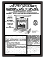
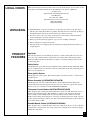
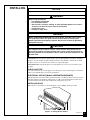
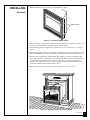
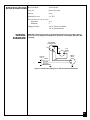
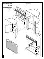
Shown with optional
cabinet mantel, hearth
base, and trim
accessories.
Save this manual for future reference.
®
WARNING: If the information in this manual is not
followed exactly, a fire or explosion may result causing
property damage, personal injury, or loss of life.
— Do not store or use gasoline or other flammable
vapors and liquids in the vicinity of this or any other
appliance.
— WHAT TO DO IF YOU SMELL GAS
• Do not try to light any appliance.
• Do not touch any electrical switch; do not use any
phone in your building.
• Immediately call your gas supplier from a
neighbor’s phone. Follow the gas supplier’s in-
structions.
• If you cannot reach your gas supplier, call the fire
department.
— Installation and service must be performed by a
qualified installer, service agency, or the gas supplier.
WARNING: Improper installation,
adjustment, alteration, service,
or maintenance can cause injury
or property damage. Refer to this
manual for correct installation
and operational procedures. For
assistance or additional infor-
mation consult a qualified in-
staller, service agency, or the
gas supplier.
WARNING: This is an unvented
gas-fired heater. It uses air (oxy-
gen) from the room in which it is
installed. Provisions for adequate
combustion and ventilation air
must be provided. Refer to
Air for
Combustion and Ventilation
sec-
tion in this manual.
This appliance may be installed in an aftermarket* manufactured (mobile) home,
where not prohibited by state or local codes.
* Aftermarket: Completion of sale, not for purpose of resale, from the manufacturer
OWNER’S OPERATION AND INSTALLATION MANUAL
DESA INTERNATIONAL
UNVENTED (VENT-FREE)
NATURAL GAS FIREPLACE
Variable
Manually-
Controlled
Models and
Thermostatically-
Controlled
“B” Models
with
Split Oak Logs

2
103416
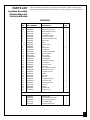
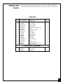
CONTENTS
SECTION PAGE
SAFETY
INFORMATION
WARNINGS
IMPORTANT: Read this owner’s manual carefully and completely before trying
to assemble, operate, or service this fireplace. Improper use of this fireplace
can cause serious injury or death from burns, fire, explosion, electrical shock,
and carbon monoxide poisoning.
DANGER
Carbon monoxide poisoning may lead to death!
Carbon Monoxide Poisoning: Early signs of carbon monoxide poisoning resemble the
flu, with headaches, dizziness, or nausea. If you have these signs, the fireplace may not be
working properly. Get fresh air at once! Have fireplace serviced. Some people are more
affected by carbon monoxide than others. These include pregnant women, people with heart
or lung disease or anemia, those under the influence of alcohol, and those at high altitudes.
Natural Gas: Natural gas is odorless. An odor-making agent is added to the gas. The odor
helps you detect a gas leak. However, the odor added to the gas can fade. Gas may be present
even though no odor exists.
Make certain you read and understand all Warnings. Keep this manual for reference. It is
your guide to safe and proper operation of this fireplace.
Safety Information continues on next page
Safety Information .................................................................................................. 2
Product Identification ............................................................................................. 4
Local Codes ............................................................................................................ 5
Unpacking............................................................................................................... 5
Product Features ..................................................................................................... 5
Air for Combustion and Ventilation ....................................................................... 6
Installing ................................................................................................................. 9
Check Gas Type .............................................................................................. 9
Electrical Hookup ............................................................................................ 9
Assembling and Attaching Brass Trim ........................................................... 10
Installation Clearances .................................................................................... 11
Conventional Fireplace Installation ................................................................ 11
Built-In Fireplace Installation ......................................................................... 14
Installing Gas Piping to Fireplace Location .................................................... 16
Connecting Fireplace to Gas Supply ............................................................... 17
Checking Gas Connections ............................................................................. 18
Installing Logs ................................................................................................. 20
Operating Fireplace (Thermostat-Controlled Models) ........................................... 22
Operating Fireplace (Manually-Controlled Models) .............................................. 24
Inspecting Burners .................................................................................................. 26
Cleaning and Maintenance ..................................................................................... 28
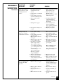
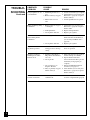
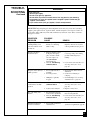
Troubleshooting ...................................................................................................... 28
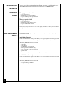
Technical Service ................................................................................................... 32
Service Hints .......................................................................................................... 32
Replacement Parts .................................................................................................. 32
Specifications ......................................................................................................... 33
Wiring Diagram ...................................................................................................... 33
Accessories ............................................................................................................. 34
Illustrated Parts Lists .............................................................................................. 36-43
Warranty Information ............................................................................................. Back Cover

3
103416
SAFETY
INFORMATION
Continued
WARNINGS
Continued
WARNING: Any change to this fireplace or its controls can be dangerous.
1. This appliance is only for use with the type of gas indicated on the rating plate. This
appliance is not convertible for use with other gases.
2. If you smell gas
• shut off gas supply
• do not try to light any appliance
• do not touch any electrical switch; do not use any phone in your building
• immediately call your gas supplier from a neighbor’s phone. Follow the gas
supplier’s instructions
• if you cannot reach your gas supplier, call the fire department
3. This fireplace shall not be installed in a bedroom or bathroom.
4. Never install the fireplace
• in a recreational vehicle
• where curtains, furniture, clothing, or other flammable objects are less than 36 inches
from the front, top, or sides of the fireplace
• in high traffic areas
• in windy or drafty areas
5. Do not use this fireplace as a wood-burning fireplace. Use only the logs provided with
the fireplace.
6. Do not add extra logs or ornaments such as pine cones, vermiculite, or rock wool. Using
these added items can cause sooting. Do not add lava rock around base. Rock and debris
could fall into the control area of fireplace.
7. You must operate this fireplace with the fireplace screen in place. Make sure fireplace
screen is in place before running fireplace.
8. This fireplace is designed to be smokeless. If logs ever appear to smoke, turn off
fireplace and call a qualified service person.
Note:
During initial operation, slight
smoking could occur due to log curing and fireplace burning manufacturing residues.
9. Do not allow fans to blow directly into the fireplace. Avoid any drafts that alter burner
flame patterns. Ceiling fans can create drafts that alter burner flame patterns. Altered
burner patterns can cause sooting.
10. Do not use a blower insert, heat exchanger insert or other accessory not approved for use
with this heater.
11. This fireplace needs fresh air ventilation to run properly. This fireplace has an oxygen
depletion sensor (ODS) pilot light safety system. The ODS shuts down the fireplace if
not enough fresh air is available. See Air for Combustion and Ventilation, pages 6
through 8. If fireplace keeps shutting off, see Troubleshooting, pages 28 through 31.
12. Do not run fireplace
• where flammable liquids or vapors are used or stored
• under dusty conditions
13. Do not use this fireplace to cook food or burn paper or other objects.
14. Never place any objects in the fireplace or on logs.
15. Fireplace front and screen becomes very hot when running fireplace. Keep children and
adults away from hot surfaces to avoid burns or clothing ignition. Fireplace will remain
hot for a time after shut-down. Allow surfaces to cool before touching.
16. Carefully supervise young children when they are in the room with fireplace.
17. Do not use fireplace if any part has been exposed to or under water. Immediately call a
qualified service technician to inspect the fireplace and to replace any part of the control
system and any gas control which has been under water.
18. Do not operate fireplace if any log is broken. Do not operate fireplace if a log is chipped
(dime-sized or larger).
19. Turn fireplace off and let cool before servicing. Only a qualified service person should
service and repair fireplace.
20. Operating fireplace above elevations of 4,500 feet could cause pilot outage.

4
103416
PRODUCT
IDENTIFICATION
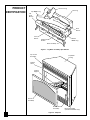
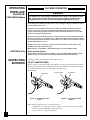
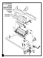
Figure 1 - Log Base Assembly, Split Oak Set
Figure 2 - Fireplace
Top Louver
Assembly
Firebox
Hood
Bottom Louver
Assembly
Screen
Assembly
Top Outer
Casing
Firebox
Support
Blower Assembly
(Thermostat Models only)
Left
Front
Branch
Rear Log
Base Assembly
Front
Burner
Rear
Burner
Crossover Log
Top Middle Log
Bottom
Middle Log
Right Front
Branch

5
103416
LOCAL CODES
Install and use fireplace with care. Follow all local codes. In the absence of local codes, use the
latest edition of The National Fuel Gas Code ANSI Z223, also known as NFPA 54*.
*Available from:
American National Standards Institute, Inc.
1430 Broadway
New York, NY 10018
National Fire Protection Association, Inc.
Batterymarch Park
Quincy, MA 02269
PRODUCT
FEATURES
UNPACKING
1. With utility knife, cut the carton all the way around above the staples on the bottom tray.
Lift the carton off the heater. Remove packing.
Note:
The hood is located in the packing on
the right hand side of the heater front. Lift the heater off the bottom tray.
2. Locate two screws above top corners of the fireplace screen. Remove and discard these
screws. Lift fireplace screen up and pull out to remove.
3. Remove protective packaging applied to logs, log base assembly, and fireplace.
4. Remove fireplace hood from carton insert.
5. Check all items for any shipping damage. If damaged, promptly inform dealer where you
bought fireplace.
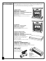
Operation
This vent-free fireplace is clean burning. It requires no outside venting. There is no heat loss
out a vent or up a chimney. Heat is generated by both realistic flames and glowing embers.
When used without the blower, the fireplace requires no electricity making it ideal for emer-
gency back-up heat.
Safety Device
This fireplace has a pilot with an Oxygen Depletion Sensor Shutoff System (ODS). The ODS/
pilot is a required feature for vent-free room heaters. The ODS system shuts off the fireplace if
there is not enough fresh air.
Piezo Ignition System
This fireplace has a piezo ignitor. This system requires no matches, batteries, or other sources
to light fireplace.
Blower Assembly (VSGF28NTB/CSGF28NTB)
This fireplace has a blower assembly. The blower operates thermostatically. The blower
circulates heated air from the fireplace into the room. Use of blower is optional. An optional
blower accessory is available for models VSGF28NV/CSGF28NV.
Thermostat Control Models (VSGF28NTB/CSGF28NTB)
These fireplaces have a thermostat sensing bulb and a control valve. The thermostat controls
the heat output and flame height. This maintains a consistent room temperature. Even the
lowest setting provides realistic flames and glowing embers from two burners. Selecting
higher comfort settings allows fireplace to run longer, producing greater heat output. At lower
comfort settings, the fireplace will run less. This results in increased heating comfort. This can
also result in lower gas bills.
Variable Manual Control (VSGF28NV/CSGF28NV)
These fireplaces have a variable manual control valve which allows the user to choose the heat
setting that best suits his needs. Any setting between low and high may be selected by simply
turning the control knob.

6
103416
AIR FOR
COMBUSTION
AND
VENTILATION
WARNING
This heater shall not be installed in a confined space unless provisions are pro-
vided for adequate combustion and ventilation air. Read the following instructions
to insure proper fresh air for this and other fuel-burning appliances in your home.
Today’s homes are built more energy efficient than ever. New materials, increased insulation,
and new construction methods help reduce heat loss in homes. Home owners weather strip and
caulk around windows and doors to keep the cold air out and the warm air in. During heating
months, home owners want their homes as airtight as possible.
While it is good to make your home energy efficient, your home needs to breathe. Fresh air must
enter your home. All fuel-burning appliances need fresh air for proper combustion and ventila-
tion.
Exhaust fans, fireplaces, clothes dryers, and fuel burning appliances draw air from the house to
operate. You must provide adequate fresh air for these appliances. This will insure proper
venting of vented fuel-burning appliances.
PROVIDING ADEQUATE VENTILATION
The following is exerpts from National Fuel Gas Code. NFPA 54/ANSI Z223.1, Section 5.3, Air
for Combustion and Ventilation.
All spaces in homes fall into one of the three following ventilation classifications:
1. Unusually Tight Contruction; 2. Unconfined Space; 3. Confined Space.
The information on pages 6 through 8 will help you classify your space and provide adequate
ventilation.
Unusually Tight Construction
The air that leaks around doors and windows may provide enough fresh air for combustion and
ventilation. However, in buildings of unusually tight construction, you must provide additional
fresh air.
Unusually tight construction is defined as construction where:
a. walls and ceilings exposed to the outside atmosphere have a continuous
water vapor retarder with a rating of one perm or less with openings
gasketed or sealed
and
b. weather stripping has been added on openable windows and doors
and
c. caulking or sealants are applied to areas such as joints around window and
door frames, between sole plates and floors, between wall-ceiling joints,
between wall panels, at penetrations for plumbing, electrical, and gas lines,
and at other openings.
If your home meets all of the three criteria above, you must provide additional
fresh air. See
Ventilation Air From Outdoors
, page 8
.
If your home does not meet all of the three criteria above, proceed to page 7.
Confined Space and Unconfined Space
The National Fuel Gas Code (ANSIZ2123.1, 1992 Section 5.3) defines a confined space as a
space whose volume is less than 50 cubic feet per 1,000 Btu per hour (4.8 m
3
per kw) of the
aggregate input rating of all appliances installed in that space and an unconfined space as a
space whose volume is not less than 50 cubic feet per 1,000 Btu per hour (4.8 m
3
per kw) of the
aggregate input rating of all appliances installed in that space. Rooms communicating directly
with the space in which the appliances are installed*, through openings not furnished with
doors, are considered a part of the unconfined space.
* Adjoining rooms are communicating only if there are doorless passageways or ventilation
grills between them.

7
103416
AIR FOR
COMBUSTION
AND
VENTILATION
Continued
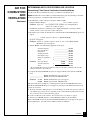
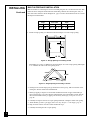
DETERMINING AIR FLOW FOR FIREPLACE LOCATION
Determining if You Have a Confined or Unconfined Space
Use this work sheet to determine if you have a confined or unconfined space.
Space: Includes the room in which you will install fireplace plus any adjoining rooms with
doorless passageways or ventilation grills between the rooms.
1. Determine the volume of the space (length x width x height).
Length x Width x Height = ___________________ cu. ft. (volume of space)
Example:
Space size 22 ft. (length) x 18 ft. (width) x 8 ft. (ceiling height) =
3168 cu. ft. (volume of space)
If additional ventilation to adjoining room is supplied with grills or openings, add the
volume of these rooms to the total volume of the space.
2. Divide the space volume by 50 cubic feet to determine the maximum Btu/Hr the space can
support.
____________ (volume of space) ÷ 50 cu. ft. = (Maximum Btu/Hr
the space can support)
Example:
3168 cu. ft. (volume of space) ÷ 50 cu. ft. = 63.3 or 63,300 (maximum
Btu/Hr the space can support)
3. Add the Btu/Hr of all fuel burning appliances in the space.
Vent-free fireplace ___________________ Btu/Hr
Gas water heater* ___________________ Btu/Hr
Gas furnace ___________________ Btu/Hr
Vented gas heater ___________________ Btu/Hr
Gas fireplace logs ___________________ Btu/Hr
Other gas appliances* + ___________________ Btu/Hr
Total = ___________________ Btu/Hr
Example:
Gas water heater 40,000 Btu/Hr
Vent-free fireplace + 28,000 Btu/Hr
Total = 68,000 Btu/Hr
* Do not include direct-vent gas appliances. Direct-vent draws combustion air from the
outdoors and vents to the outdoors.
4. Compare the maximum Btu/Hr the space can support with the actual amount of Btu/Hr
used.
_________________ Btu/Hr (maximum the space can support)
_________________ Btu/Hr (actual amount of Btu/Hr used)
Example:
63,300 Btu/Hr (maximum the space can support)
68,000 Btu/Hr (actual amount of Btu/Hr used)
The space in the above example is a confined space because the actual Btu/Hr used is more
than the maximum Btu/Hr the space can support. You must provide additional fresh air. Your
options are as follows:
A. Rework work sheet, adding the space of an adjoining room. If the extra space provides an
unconfined space, remove door to adjoining room or add ventilation grills between rooms.
See Ventilation Air from Inside Building, page 8.
B. Vent room directly to the outdoors. See Ventilation Air from Outdoors, page 8.
C. Install a lower Btu/Hr fireplace, if lower Btu/Hr size makes room unconfined.
If the actual Btu/Hr used is less than the maximum Btu/Hr the space can support, the space is
an unconfined space. You will need no additional fresh air ventilation.
Continued

8
103416
AIR FOR
COMBUSTION
AND
VENTILATION
Continued
WARNING ICON G001
WARNING
If the area in which the heater may be operated is smaller than that defined as an
unconfined space, provide adequate combustion and ventilation air by one of the
methods described in the
National Fuel Gas Code, ANSI Z223.1, 1992, Section 5.3.
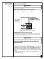
VENTILATION AIR
Ventilation Air From Inside Building
This fresh air would come from an adjoining unconfined space. When ventilating to an
adjoining unconfined space, you must provide two permanent openings: one within 12" of the
ceiling and one within 12" of the floor on the wall connecting the two spaces (see options 1 and
2, Figure 3). You can also remove door into adjoining room (see option 3, Figure 3). Follow the
National Fuel Gas Code NFPA 54/ANSI Z223.1, Section 5.3, Air for Combustion and Ventila-
tion for required size of ventilation grills or ducts.
WARNING ICON G001
WARNING
Rework worksheet, adding the space of the adjoining unconfined space. The
combined spaces must have enough fresh air to supply all appliances in both
spaces.
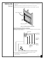
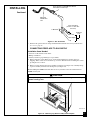
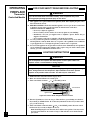
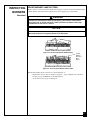
Figure 4 - Ventilation Air from Outdoors
Ventilation Air From Outdoors
Provide extra fresh air by using ventilation grills or ducts. You must provide two permanent
openings: one within 12" of the ceiling and one within 12" of the floor. Connect these items
directly to the outdoors or spaces open to the outdoors. These spaces include attics and crawl
spaces.
IMPORTANT:
Do not provide openings for inlet or outlet air into attic if attic has a thermostat-
controlled power vent. Heated air entering the attic will activate the power vent.
Figure 3 - Ventilation Air from Inside Building
Outlet
Air
Ventilated
Attic
Outlet
Air
Inlet
Air
Inlet Air
Ventilated
Crawl Space
To
Crawl
Space
To Attic
Or
Remove
Door into
Adjoining
Room,
Option
3
Ventilation Grills
Into Adjoining Room,
Option 2
Ventilation
Grills
Into Adjoining
Room,
Option 1
12"
12"

9
103416
INSTALLING
Continued
NOTICE
A qualified service person must install fireplace. Follow all local codes.
WARNING ICON G 001
WARNING
Never install the fireplace
• in a bedroom or bathroom
• in a recreational vehicle
• where curtains, furniture, clothing, or other flammable objects are less than
36 inches from the front, top, or sides of the fireplace
• in high traffic areas
• in windy or drafty areas
WARNING
Models VSGF28NTB/CSGF28NTB have a three-prong, grounded electrical plug.
This plug helps protect you against electrical shock. Only connect plug to a
properly grounded, three-prong receptacle. Do not cut or remove the grounding
prong from this plug.
WARNING ICON G 001
CAUTION
This fireplace creates warm air currents. These currents move heat to wall sur-
faces next to fireplace. Installing fireplace next to vinyl or cloth wall coverings or
operating fireplace where impurities in the air (such as tobacco smoke) exist, may
discolor walls.
IMPORTANT:
Vent-free heaters add moisture to the air. Although this is beneficial, installing
fireplace in rooms without enough ventilation air may cause mildew to form from too much
moisture. See Air for Combustion and Ventilation, pages 6 through 8.
IMPORTANT:
Make sure the fireplace is level. If fireplace is not level, log set will not work
properly.
CHECK GAS TYPE
Use only natural gas. If your gas supply is not natural gas, do not install fireplace. Call dealer
where you bought fireplace for proper type fireplace.
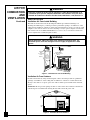
ELECTRICAL HOOKUP (Models VSGF28NTB/CSGF28NTB)
This fireplace has a blower assembly with an electrical cord. The electrical cord is five feet in
length. You must locate fireplace within reach of a 120 volt grounded electrical outlet. If not,
you must install an electrical outlet within reach of fireplace power cord.
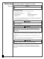
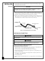
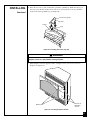
INSTALLING HOOD
Install hood to top of firebox as shown in Figure 5. Use 3 Phillips screws provided.
Figure 5 - Installing Hood to Firebox

10
103416
INSTALLING
Continued
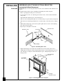
ASSEMBLING AND ATTACHING OPTIONAL BRASS TRIM
(Included with Mantel Accessory)
IMPORTANT:
If you are recessing the firebox in a wall, do not attach brass trim at this time. See
page 13.
Note:
The instructions below show assembling and attaching brass trim to fireplace.
1. Remove packaging from three pieces of brass trim.
2. Locate four brass screws, two adjusting plates with set screws, and two shims in the hard-
ware packet.
3. Align shim under adjusting plate as shown in Figure 6.
4. Slide one end of adjusting plate/shim in slot on mitered edge of top brass trim (see Figure 6).
5. Slide other end of adjusting plate/shim in slot on mitered edge of side brass trim (see Figure
6).
6. While firmly holding edges of brass trim together, tighten both set screws on the adjusting
plate with slotted screwdriver.
7. Repeat steps 1 through 6 for other side.
Side Brass Trim
Top Brass Trim
Slot
Mitered Edge
Slot
Shim
Set Screws
Adjusting
Plate
Figure 6 - Assembling Brass Trim
Trim Hanging
Screws
Assembled
Brass Trim
8. Tighten trim hanging screws (#10 x 6.25 shoulder) into holes in cabinets. Place the as-
sembled trim onto fireplace cabinet. Align hanging notches on trim with hanging screws on
side of fireplace (see Figure 7). Push trim firmly into place, sliding hanging notches over
hanging screws.
Hanging
Notches on Trim
Figure 7 - Attaching Brass Trim to Fireplace

11
103416
INSTALLING
Continued
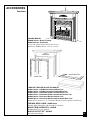
INSTALLATION CLEARANCES
Note: Clearances
are the same if
using optional
cabinet mantel or
built-in installation.
WARNING ICON G 001
WARNING
Maintain the minimum clearances. If you can, provide greater clearances from
floor, ceiling, and adjoining wall.
Continued
MINIMUM CLEARANCE
Side Wall - 16 " Cabinet and
Face Mantel
Ceiling - 42" Corner Mantel
Floor - 0"
Carefully follow the instructions below. This will ensure safe installation.
Minimum Wall and Ceiling Clearances (see Figure 8)
A. Clearances from the side of the fireplace opening to any combustible wall should not be less
than 16 inches for a cabinet mantel or 12 inches for a corner installation.
B. Clearances from the top of the fireplace opening to the ceiling should not be less than 42
inches.
WARNING ICON G 001
WARNING
For conventional installation, it is recommended you use the cabinet mantel,
corner mantel, face mantel, or hearth bases specified in this manual. Surface
clearances may not be sufficient with other cabinet mantels and hearth bases.
This may create a fire hazard. See
Accessories,
pages 34 and 35 for correct
mantels and hearth bases.
CONVENTIONAL FIREPLACE INSTALLATION
Conventional installation of this fireplace involves installing fireplace along with the corner,
face, or cabinet mantel with hearth base accessories against a wall in your home. Follow the
instructions below to install the fireplace in this manner.
Figure 8 - Minimum Clearance to Wall and Ceiling
42"
16"
Face or
Cabinet
Mantel
Corner
Mantel
12"
Note:
The instructions below show installation using the cabinet mantel and the
G3000F/G3001U series hearth base accessories. The hearth base accessory shown is optional
for this installation. You can install fireplace and cabinet mantel directly on the floor. The corner
mantel and face mantel accessories cannot be installed with the G3000F/G3001U hearth base.
You must install corner and face mantel directly on the floor. If mounting fireplace and cabinet
mantel to the floor or using face mantel or corner mantel, an optional G3005 Slim Base kit may
be installed.
1. Assemble cabinet mantel, hearth base, and trim accessories. Assembly instructions are
included with each accessory.

12
103416
INSTALLING
Continued
2. When installing blower, install a properly grounded, 120 volt three-prong electrical outlet at
fireplace location if an outlet is not there. If possible, locate outlet so cabinet mantel will
cover it when installed (see Figure 9).
3. Install gas piping to fireplace location. This installation includes an approved flexible gas
line (if allowed by local codes) after the manual shutoff valve. The flexible gas line must be
the last item installed on the gas piping. See Installing Gas Piping to Fireplace Location,
page 16.
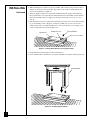
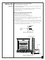
4. Place hearth base accessory against wall at installation location. Cut an access hole in hearth
top to run flexible gas line to fireplace (see Figure 9). Make sure to locate access hole so
cabinet mantel will cover it when installed. Note: You can secure base to floor using wood
screws. Countersink screw heads and putty over.
Figure 9 - Placing Hearth Base Accessory Against Wall
5. Route flexible gas line through access hole in hearth base.
6. Center cabinet mantel on hearth base (see Figure 10). Make sure mantel is flush against wall.
Figure 10 - Installing Cabinet Mantel
Electrical Outlet
Hearth Base
Flexible Gas Line
Gas Line Access Hole
Cabinet Mantel

13
103416
INSTALLING
Continued
8. Place cardboard or other protective material on top of hearth base. Carefully set fireplace on
protective material, with back of fireplace inside mantel opening.
9. Attach flexible gas line to fireplace gas regulator. See Connecting Fireplace to Gas Supply,
page 17.
10.If blower is installed, route blower electrical cord through access holes in either side of fire-
place.
Note:
Bushing may be moved if necessary. Plug electrical cord into electrical outlet.
11.Carefully insert fireplace into cabinet mantel. Be careful not to scratch or damage hearth
base, cabinet mantel, or any laminate trim on hearth base. Remove protective material from
top of hearth base and from front of fireplace (if any). Note: You can secure fireplace to
hearth or floor. Open lower louver. Locate screw holes in bottom of base. Tighten wood
screws through these holes and into hearth or floor.
12.Check all gas connections for leaks. See Checking Gas Connections, page 18.
Continued
Figure 12 - Inserting Fireplace Into Cabinet Mantel
7. Break off nailing flanges (see Figure 11) with hammer or pliers.
Figure 11 - Location of Nailing Flanges
Nailing Flanges

14
103416
INSTALLING
Continued
39 3/8"
27 7/8"
55 5/8"
35 1/2"
Figure 14 - Rough Opening for Installing in Corner
If installing in a corner, use dimensions shown in Figure 14 for the rough opening. The height
is 33" which is the same as the wall opening above.
2. If using blower, install and properly ground GA3555, three-prong 120 volt electrical outlet,
in fireplace. Follow instructions included in kit.
3. Install gas piping to fireplace location. This installation includes an approved flexible gas
line (if allowed by local codes) after the manual shutoff valve. The flexible gas line must be
the last item installed on the gas piping. See Installing Gas Piping to Fireplace Location,
page 16.
4. Carefully set fireplace in front of rough opening with back of fireplace inside wall opening.
5. Attach flexible gas line to gas supply. See Connecting Fireplace to Gas Supply, page 17.
6. Plug electrical cord into electrical outlet installed in step 2.
7. Carefully insert fireplace into rough opening.
1. Frame in rough opening. Use dimensions shown in Figure 13 for the rough opening.
35 1/2"
17 3/4"
33"
Figure 13 - Rough Opening for Installing in Wall
BUILT-IN FIREPLACE INSTALLATION
Built-in installation of this fireplace involves installing fireplace into a framed-in enclosure. This
makes the front of fireplace flush with wall. If installing a mantel above the fireplace, but you
must follow the clearances shown in Figure 16 , page 15. Follow the instructions below to install
the fireplace in this manner.
Height Front Width Depth
Actual Framing Actual Framing Actual Framing
32
3
/
8
" 33" 34
5
/
16
" 35
1
/
2
" 16
11
/
16
" 17
3
/
4
"

15
103416
INSTALLING
Continued
Figure 15 - Attaching Fireplace to Wall Studs
Nailing Flanges
Mantel Clearances for Built-In Installation
If placing mantel above built-in fireplace, you must meet minimum clearance between mantel
shelf and top of fireplace opening.
If your installation does not meet the above minimum clearances, you must:
• raise the mantel to an acceptable height, OR
• remove the mantel.
Distances to
Underside of
Mantel
Underside of
Mantel Shelf
20" 24
1
/2" 27
1
/2" 30"
All minimum
distances are
in inches
Top of
Fireplace
Opening
2
1
/2
"
6"
8"
10"
Figure 16 - Minimum Mantel Clearances for Built-In Installation
Mantel Shelf
Nails or Wood Screws
8. Attach fireplace to wall studs using nails or wood screws through holes in nailing flange (see
Figure 15).
9. Check all gas connections for leaks. See Checking Gas Connections, page 18.
10.Install brass trim after final finishing and/or painting of wall (see Figure 7, page 10).
Continued

16
103416
INSTALLING
Continued
INSTALLING GAS PIPING TO FIREPLACE LOCATION
Installation Items Needed
Before installing fireplace, make sure you have the items listed below.
• piping (check local codes)
• sealant (resistant to LP/propane gas)
• manual shutoff valve *
• test gauge connection *
• sediment trap
• tee joint
• pipe wrench
• approved flexible gas line with gas
connector (if allowed by local
codes) (not provided)
NOTICE
A qualified service person must connect fireplace to gas supply. Follow all local
codes.
* An A.G.A. design-certified manual shutoff valve with 1/8" NPT tap is an acceptable alterna-
tive to test gauge connection. Purchase the optional A.G.A. design-certified manual shutoff
valve from your dealer. See Accessories, page 34.
WARNING ICON G 001
WARNING
Never connect fireplace to private (non-utility) gas wells. This gas is commonly
known as well-head gas.
WARNING ICON G 001
CAUTION
Use only new, black iron or steel pipe. Internally-tinned copper tubing may be
used in certain areas. Check your local codes. Use pipe of 1/2" diameter or greater
to allow proper gas volume to fireplace. If pipe is too small, undue loss of pres-
sure will occur.
Installation must include a manual shutoff valve, union, and plugged 1/8" NPT tap. Locate NPT
tap within reach for test gauge hook up. NPT tap must be upstream from fireplace (see Figure
17, page 17).
Check your building codes for any special requirements for locating manual shutoff valve to
fireplaces.
Apply pipe joint sealant lightly to male threads. This will prevent excess sealant from going into
pipe. Excess sealant in pipe could result in clogged fireplace valves.
WARNING ICON G 001
CAUTION
Use pipe joint sealant that is resistant to liquid petroleum (LP) gas.
Install sediment trap in supply line as shown in Figure 17, page 17. Locate sediment trap where
it is within reach for cleaning. Locate sediment trap where trapped matter is not likely to
freeze. A sediment trap traps moisture and contaminants. This keeps them from going into
fireplace gas controls. If sediment trap is not installed or is installed wrong, fireplace may not
run properly.

17
103416
INSTALLING
Continued
A.G.A. Design-Certified Manual Shutoff
Valve With 1/8" NPT Tap*
3" Minimum
From Gas Meter
(5" W.C. to 10.5" W.C.
Pressure)
Approved
Flexible Gas
Line
Tee Joint
Pipe Nipple
Cap
Sediment
Trap
Figure 17 - Gas Connection
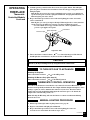
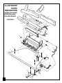
Figure 18 - Removing Log Base Assembly From Fireplace
Continued
WARNING ICON G 001
CAUTION
Do not pick up log base assembly by burners. This could damage burners. Only
handle base by grates.
Installation Items Needed
• 5/16" hex socket wrench or nut-driver
• Phillips screwdriver
• sealant (resistant to propane/LP gas, not provided)
1. Remove fireplace screen. Remove two screws that hold fireplace screen in place for
shipping. These screws are located near top of screen. Discard screws. Lift fireplace screen
up and pull out to remove.
2. Remove screws that attach log base assembly to fireplace (see Figure 18). Carefully lift up
log base assembly and remove from fireplace (see Figure 18).
Note:
If adding the G8000 series brick liner accessory, install it now. Follow instructions in
G8000 accessory kit.
CONNECTING FIREPLACE TO GAS SUPPLY
* Purchase the optional A.G.A. design-certified manual shutoff valve from your dealer. See
Accessories, page 34.

18
103416
INSTALLING
Continued
3. Route flexible gas line from manual shutoff valve to fireplace. Route flexible gas supply
line through one of the access holes.
Pressure Testing Gas Supply Piping System
Test Pressures In Excess Of 1/2 PSIG
1. Disconnect fireplace and its individual manual shutoff valve from gas supply piping system.
Pressures in excess of 1/2 psig will damage fireplace gas regulator.
2. Cap off open end of gas pipe where manual shutoff valve was connected.
3. Pressurize supply piping system by either using compressed air or opening main gas valve
located on or near gas meter.
4. Check all joints of gas supply piping system. Apply mixture of liquid soap and water to gas
joints. Bubbles forming show a leak.
5. Correct all leaks at once.
6. Re-connect fireplace and manual shutoff valve to gas supply. Check re-connected fittings for
leaks.
CHECKING GAS CONNECTIONS
WARNING ICON G 001
WARNING
Test all gas piping and connections for leaks after installing or servicing. Correct
all leaks at once.
WARNING ICON G 001
WARNING
Never use an open flame to check for a leak. Apply a mixture of liquid soap and
water to all joints. Bubbles forming show a leak. Correct all leaks at once.
Figure 19 - Attaching Flexible Gas Lines Together
4. Attach a 45° flare union gas connector to flexible gas line from gas supply (see Figure 19).
Connect flare union to flexible gas line attached to gas regulator of fireplace (see Figure 19).
5. Check all gas connections for leaks. See Checking Gas Connections, below.
6. Replace log base assembly back into fireplace. Feed flexible gas line into fireplace base area
while replacing log base assembly. Make sure the entire flexible gas line is in fireplace base
area. Reattach log base assembly to fireplace with screws removed in step 3.
NOTICE
Most building codes do not permit concealed gas connections. A flexible gas line
is provided to allow accessibility from the fireplace. The flexible gas supply line
connection to the manual shutoff valve should be accessible.
Flexible Gas Line from
Fireplace Gas Regulator
To Fireplace
Gas Regulator
Flare Union
Flexible Gas Line from
Manual Shutoff Valve
Manual Shutoff Valve
➞
➞
To Gas Meter

19
103416
INSTALLING
Continued
Test Pressures Equal To or Less Than 1/2 PSIG
1. Close manual shutoff valve (see Figure 20).
2. Pressurize supply piping system by either using compressed air or opening main gas valve
located on or near gas meter.
3. Check all joints from gas meter to manual shutoff valve (see Figure 21). Apply mixture of
liquid soap and water to gas joints. Bubbles forming show a leak.
4. Correct all leaks at once.
Pressure Testing Fireplace Gas Connections
1. Open manual shutoff valve (see Figure 20).
2. Open main gas valve located on or near gas meter.
3. Make sure control knob of fireplace is in the OFF position.
4. Check all joints from manual shutoff valve to thermostat gas valve (see Figure 21). Apply
mixture of liquid soap and water to gas joints. Bubbles forming show a leak.
5. Correct all leaks at once.
6. Light fireplace (see Operating Fireplace, pages 22 and 23 [Thermostat-controlled models]
or pages 24 and 25 [Manually-controlled models]). Check all other internal joints for leaks.
7. Turn off fireplace (see To Turn Off Gas to Appliance, page 23 [Thermostat-controlled
models] or page 25 [Manually-controlled models]).
Figure 20 - Manual Shutoff Valve
ON
POSITION
OFF
POSITION
Open
Closed
Manual
Shutoff
Valve
Manual Shutoff Valve
Figure 21 - Checking Gas Joints
Manual Gas Valve
Gas Meter
Continued

20
103416
INSTALLING
Continued
WARNING
Failure to position the parts in accordance with these diagrams or failure to use
only parts specifically approved with this heater may result in property damage or
personal injury.
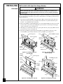
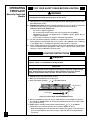
INSTALLING LOGS (Split Oak Design Models)
Bottom Middle Log (#2)
Metal Post
Metal Post
Peg
Groove
Groove
Grate
Each log is marked with a number. These numbers will help you identify the log when installing.
It is very important to install these logs exactly as instructed. Do not modify logs. Only use logs
supplied with heater.
1. Place front logs (#1L and #1R) on top of the grate. Make sure the notches in the bottom of
the logs fit over the grate prongs (see Figure 22). Push back of logs flush with metal grate
bar. Note: 18" model has only one front log.
2. Rest bottom middle log (#2) behind metal posts on front burner. Make sure the grooves in the
bottom of the log fit over the grate. Bring the log forward next to the metal posts. The pegs
on the log must be on top (see Figure 23).
3. Slide the grooves in the back of the rear log (#3) against the rear grate prongs. Make sure the
peg on the log is on top (see Figure 24).
4. Place the top middle log (#4) on the bottom middle log (#2). Make sure the pegs of the
bottom middle log fit securely in the holes of the top middle log (see Figure 25).
Figure 22 - Installing Front Logs
(#1L and #1R)
Grate
Prongs
Metal Grate Bar
Front Log (#1L)
Notch
Front Log (#1R)
Figure 23 - Installing Bottom
Middle Log (#2)
Rear Log (#3)
Peg
Grate
Prong
Grate
Prong
Rear
Burner
Groove
in Back
of Log
Groove
in Back
of Log
Figure 24 - Installing Rear Log (#3)
Top Middle Log (#4)
Hole
Hole
Peg
Peg
Bottom
Middle Log
Figure 25 - Installing Top Log (#4)
Peg
Page is loading ...
Page is loading ...
Page is loading ...
Page is loading ...
Page is loading ...
Page is loading ...
Page is loading ...
Page is loading ...
Page is loading ...
Page is loading ...
Page is loading ...
Page is loading ...
Page is loading ...
Page is loading ...
Page is loading ...
Page is loading ...
Page is loading ...
Page is loading ...
Page is loading ...
Page is loading ...
Page is loading ...
Page is loading ...
Page is loading ...
Page is loading ...
-
 1
1
-
 2
2
-
 3
3
-
 4
4
-
 5
5
-
 6
6
-
 7
7
-
 8
8
-
 9
9
-
 10
10
-
 11
11
-
 12
12
-
 13
13
-
 14
14
-
 15
15
-
 16
16
-
 17
17
-
 18
18
-
 19
19
-
 20
20
-
 21
21
-
 22
22
-
 23
23
-
 24
24
-
 25
25
-
 26
26
-
 27
27
-
 28
28
-
 29
29
-
 30
30
-
 31
31
-
 32
32
-
 33
33
-
 34
34
-
 35
35
-
 36
36
-
 37
37
-
 38
38
-
 39
39
-
 40
40
-
 41
41
-
 42
42
-
 43
43
-
 44
44


Desa VSGF28NV Owner's manual
- Category
- Fireplaces
- Type
- Owner's manual
Ask a question and I''ll find the answer in the document
Finding information in a document is now easier with AI
Related papers
-
Desa Tech GFP28MLP Owner's manual
-
-
Desa Tech VGF28PT Owner's manual
-
-
-
-
-
-
Desa Tech CSGF28NV Owner's manual
-
Other documents
-
Vanguard Heating VSGF28NVA User manual
-
Vinotemp VT-DIAMONDBIN User guide
-
-
Vanguard Heating VSGF28PTC User manual
-
Real Flame 8050E-DW User manual
-
FMI VFF KD 100 Operating instructions
-
-
Design House 561696 Installation guide
-
-