Page is loading ...

December
1979
FORM:
OM-1523
Effective
With
Serial
No.
HK328924
MODEL
SWINGARC
DIGITAL
-2
12
SWINGARC
DIGITAL
-2
16
OWN
ERS
MANUAL
!I!111EI
MILLER
ELECTRIC
MFG.
CO.
718
S.
BOUNDS
ST.
P.O.
Box
1079
APPLETON
WI
54912
USA
ADDITIONAL
COPY
PRICE
90
CENTS
NWSA
CODE
NO.
4579
PAINTED
IN
U.S.A.

~P
LIMITED
WARRANTY
EFFECTIVE:
JANUARY
I,
1979
This
warranty
supersedes
all
previous
MILLER
warranties
and
is
cx-
S
clusive
with
no
other
guarantees
or
warranties
expressed
or
implied.
LIMITED
WARRANTYSubject
to
the
terms
and
conditions
As
a
matter
of
general
policy
only,
Miller
may
honor
claims
hereof,
Miller
Electric
Mfg.
Co.,
Appleton,
Wisconsin
warrants
to
su~t~itted
by
the
original
user
within
the
foregoing
periods.
its
Distributor/Dealer
that
all
new
and
unused
Equipment
furnished
S
by
Miller
is
free
from
defect
in
workmanship
and
material
as
of
the
In
the
case
of
Millers
breach
of
warranty
or
any
other
duty
time
and
place
of
delivery
by
Miller.
No
warranty
is
made
by
Miller
with
respect
to
the
quality
of
any
goods,
the
exclusive
remedies
with
respect
to
engines,
trade
accessories
or
other
items
manu-
therefor
shall
be,
at
Millers
option,
(1)
repair
or
(2)
replacement
or,
factured
by
others.
Such
engines,
trade
accessories
and
other
where
authorized
to
writing
by
Miller
in
appropnate
cases,
(3)
the
items
are
sold
subject
to
the
warranties
of
their
respective
manu-
reasonable
cost
of
repair
or
replacement
at
an
authorized
Miller
ser
facturers,
if
any.
At
the
present
time,
the
manufacturers
warranty
on
vice
station
or
(4)
payment
of
or
credit
for
the
purchase
price
(less
the
Mag-Diesel
engine
on
DEL-200
is
limited
to
six
months
and
on
reasonable
depreciation
based
upon
actual
use)
upon
return
of
the
all
other
engines
to
one
year.
goods
at
Customers
risk
and
expense.
Upon
receipt
of
notice
of
apparent
defect
or
failure,
Miller
shall
instruct
the
claimant
on
the
~
Except
as
specified
below,
Millers
warranty
does
not
apply
to
warranty
claim
procedures
to
be
followed.
components
having
normal
useful
life
of
less
than
one
(1)
year,
such
ANY
EXJRESS
WARRANTY
NOT
PROVIDED
HEREIN
AND
as
spot
welder
tips,
relay
and
contactor
points,
MILLERMATIC
parts
ANY
IMPLIED
WARRANTY
GUARANTY
OR
REPRESENTA
that
come
in
contact
with
the
welding
wire
including
nozzles
aM
TION
AS
TO
PERFORMANCE,
AND
ANY
REMEDY
FOR
nozzle
insulators
where
failure
does
not
result
from
defect
in
BREACH
OF
CONTRACT
WHICH,
BUT
FOR
THIS
PROVISION,
workmanship
or
material.
MIGHT
ARISE
BY
IMPLICATION,
OPERATION
OF
LAW,
CUS
TOM
OF
TRADE
OR
COURSE
OF
DEALING
INCLUDING
ANY
Miller
shall
be
required
to
honor
warranty
claims
on
warranted
IMPLIED
WARRANTY
OF
MERCHANTABILITY
OR
OF
FITNESS
Equipment
in
the
event
of
failure
resulting
from
a
defect
within
the
FOR
PARTICULAR
PURPOSE,
WITH
RESPECT
TO
ANY
AND
following
periods
from
the
date
of
delivery
of
Equipment
to
the
ALL
EQUIPMENT
FURNISHED
BY
MILLER
IS
EXCLUDED
J
original
user:
AND
DISCLAIMED
BY
MILLER.
I.
Arc
welders,
power
sources
aM
components
. .
.
.
1
year
EXCEPT
AS
EXPRESSLY
PROVIDED
BY
MILLER
IN
WRIT-
2.
Original
main
power
rectifiers
3
years
ING,
MILLER
PRODUCTS
ARE
INTENDED
FOR
ULTIMATE
(labor
-
I
year
only)
PURCHASE
BY
COMMERCIAL/INDUSTRIAL
USERS
AND
FOR
3.
All
welding
guns
and
feeder/g~s
90
da~
OPERATION
BY
PERSONS
TRAINED
AND
EXPERIENCED
IN
4.
All
other
Millermatic
Feeders
1
year
THE
USE
AND
MAINTENANCE
OF
WELDING
EQUIPMENT
AND
5.
Replacement
or
repair
parts,
exclusive
of
labor
. -
60
days
NOT
FOR
CONSUMERS
OR
CONSUMER
USE.
MILLER
WAR-
6.
Batteries
6
months
RANTIES
DO
NOT
EXTEND
TO,
AND
NO
RESELLER
IS
provided
that
Miller
is
notified
in
writing
within
thirty
(30)
days
of
AUTHORIZED
TO
EXTEND
MILLERS
WARRANTIES
TO,
the
date
of
such
failure.
ANY
CONSUMER.
~
,5
~t.
_..,I,
~
~
~%
~
...~b
...-~%
--~~b

ERRATA
SHEET
After
this
manual
was
printed,
refinements
in
equipment
design
occurred.
This
sheet
lists
exceptions
to
data
appearing
later
in
this
manual.
AMENDMENT
TO
SECTION
3
-
iNSTALLATION
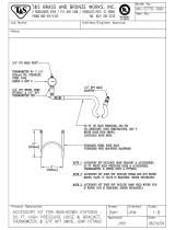
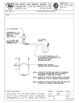
Amend
Section
3-11.
MOTOR
CONTROL
CONNECTION
(Figure
3-8)
A
receptacle
is
provided
for
connecting
the
motor
control
plug
to
the
control.
Align
keyways
and
insert
the
plug
from
the
control
end
of
the
boom
into
the
receptacle
and
rotate
the
plug
threaded
collar
clockwise
as
far
as
possible..
AMENDMENT
TO
SECTION
7
-
TROUBLESHOOTING
T~
Quantity
Item
Or
Dia.
Part
Replaced
Model
Page
No.
Mkgs.
No.
With
Description
12
I
16
37
047
901
046
757
CONTROL
BOX
(EffW/JA364525)
1
1
140
047
227
045
896
CIRCUIT
CARD,
motor
speed
(Eff
W/JA386589)
1
1
148
047
104
046 754
BRACKET,
mtg
-
gas/water
(EffW/JA364525)
1
1
158
047107
046751
CASE
SECTION,
front/bottom/back
(Eff
W/JA364525)
1
1
Page
8
C57
035
835
031
677
CAPACITOR,
tantalum
5.6
uf
35
volts
dc 2
2
Page
8
D50-54,
56-60
026202
026202
DIODE(qtychange)
10
10
Page
8
R51,53-57,
63,64,68,
74,75,81,
82,84,89
035
827
035 827
RESISTOR
(qty
change)
15
15
Page
8
R67
039
331
039
331
RESISTOR
(qty
change)
1
1
Page
8
R80
035
886
035
886
RESISTOR
(qty
change)
1 1
179
047170
045391
TUBING,neoprene3/8IDx3/32waIlx8
2 2
181
047171
045390
LINER,monocoil3/32-1/8wirex9
2
2
189
073
664
024
605
BEARING,
baIl
1
197
073
695
047 224
KNOB,
t-bar
1
1
051
297
ADAPTER
(added
to
item
15)
1
1
010
193
TUBING
2
2
048
336
COVER
STOP
2
2
045233
GUIDE,
antiwear
2
2
079
029
NUT,
hex-full
3/4-16
1
t045
503
LOCKING
COVER
1
1
tOptional
Parts.
BE
SURE
TO
PROVIDE
MODEL
AND
SERIAL
NUMBERS
WHEN
ORDERING
REPLACEMENT
PARTS.
-
-
-.
aM-i
523
Page
A

~CR1
~C65
.
cci,
CR3
~
(
a.
47
LEFT
SIDE
JI
CR2
CR2
J2
RIGOT
SIDE
_~
A
53
48
.14
33
1135
AC
-I
__________________________
1
2
3
1
~
I
P1
2
tIk
LEFT
RIGIIT
L.)
BURNBACEF
61IRRBACRR
8$
Cw
87
Cw
6
________
4
S
6
4
5
B
LEFT
IRIGIIT
R?
B
j
RC,e
C)
FLj
PCI
C,
C
OPTIONAL
REMOTE
.IIIJ2
_
8IA~
RII.IIT
T1
CONTACTOR
0
dEl
BRIGHt
RURNBACIIS
I
REs
.
CONTROL
~
245
AC
P1.03
PLCII
~
~
PESPEC
TO
INSTALL
.
~
PLC23
3>~R,__o
>>~
II7
3
~BC4
RCKII
S
_____
_______
3
ITO
_______
______
~~AO_
lot
P1.04
PLG1U
______
-5
I
WATER
I
>
5-
>~
~~AC~0_~j
PIG14
DE2
~
En
131100CR
C~3
CR~J1~~J
I
SOLENOID
I
1~2~s.o_1
-
I~T3~~
WI~<<
WIT
LOPTIONAL
J
I
GAS
SOLENOID
CR4
RIGHT
SIDE
~
i~
,._..f_1
Iaii
fR4
*Cl
II
LEFT
SIDE
ti1
I-~
~l
________
~
DRITE
IOTOR
LEFTI
I
~
I
GAS
SOLENOID
__<~~~
E~]1~i
II
~~~
~S2
~_
I
~
4
4
~
~
161
RC5
~
~
F
C
~
~.
PEG?
PLOSPEGI
I
J0c~a
I
CR~J
CR,
L_.H~4___.k
<
ICR
CR3
CR~
___
T4~EJ
Il~IIJ
LEFT
RLUOTE
RIGIIT
REMOTE
FIG,34
CI~~
L_~
IINCII
A
C151
B\f
0
0
1
)fC
v~
_____
14
4>
GIN
>>
.
RMTI)4.J4
L
STD
~RMT
I~5
Q~
us
T53
ILK
)I;3~
48
____
____
cw
40
______
____
2>
~II~
j~
4
1iiE~Eiiiiii
T
dI
R
CR3
3>
RIO
~
TCR3
44
P11.I5
PCI3
II
Z
RICIIT
TRIGGER
CR~J
T~
c~
~
C61~J.1
I
___________________
~.
c~II
R
*
B
B
__________________
6
6
~I
A52
L_4
,
,i,
ILK
LT74I4
253
3c~.-
c~
~
51
032
rs.~
~
I!]
l~
~
_
C75
-
C4$
B
-
__j
RI
mBl
161
6
I
Ill
_______
B
I
III
_______
B
C5IG~s
70
C.~
jBI!~Et
.
1
~
tii
T
R
~
C?.
C57
C6,
~
~
i.Oc,J
I
0571
:S~E:.~i!~~
42
5
~C5
~
RC5
PLGB
0107
RCR~
~
IAA
103
CR50
CR50
P
AC
IDE
HER
~
B
Circuit
Diagram
No.
C-046
829
TO
FuSEOTt~1,z
4
1155CC
METER
Figure
7-1.
Circuit
Diagram
For
Models
Effective
With
Serial
No.
JA364526
Thru
JA386588

~
ALL
WRIE
F~MS
AT
300
IPU-UOTOR
RUNNING
ALL
VOLTAGES
.IEASURRD
WITh
RESPECT
TO
CR1
COMMON
POINT
J
IXCEPT
H.
MEASURE
H
CR3
TN
RESPECT
TO
POINT
I1
RAE
R5RG(
J
~
LEPTSIDEJI
LE~I
CR2
CR2
I
~CR5
1
RIGHT
$100
WI
PLGIT
PLGI4
~$s.~W~asa.~i
~
m
~
I.s,
~I,
~)
PL~
Rl$RAC.I
P
URNACII*
'
LJLJ
RC,
~JOOOOOQOOOQ~
5LEFTERIGIIT
BURNDSCRS
________________
OPTIONAL.
REMOVE
.IIIJ3
_____________
RIGHT
CONDCTOR
~t
~
_.JL.Jl
LEFT
CONTACIOR
CONTROL
TIE
AC
~
~
PI.GII
_____________
RISPEC.
TO
INSTALL
PLC2
004
RCII1I
G~
2>~WG1T
>~_
I>~~
).)L
CR5
sli
I>
~
>)~
~
I
I
i
WAlER
I
LEFT
L~JJ
Li
I
I
SOLENOID
I
I
~f~~J1
~
~G4
PLAtO
GASSOLENOID
CR4
I~T4-x~.3ffk(
WNT
~:
~
TRIGGER
CR3
I
L~~~J
I
PLC11
002
_A
t~1
RIGHT
SIDE
24
ii
GAS
SOLENOID
IC
PT
SIDE
MOTOR
LEFTI
I
\3/
HI
j~
~
~
(
~Ei~
23
I
2
Nd
I
0
~
~
34
J7
38
4
4
.32
.12
CR31
COt
NJ
II
23
CR3
FCW
75~~
I~f
s
p
c
p
RCI
~G7
~13~G$
CR3
CRS
RCII
tII
54T~~
11,61.1
LEFT
REMOTE
RIGTIT
RE..OTE
T~4~Ei1
47
____
CR
Ss
______
____
1S~
)I~
RI8l}~0,~L
.1,
PLC13
I
CAl
L0~t!..
INC..
A
C
5
0
STD
IRMT
~>.~11T
).~L
43
CR$
Ii~
J>~~3LD
~
ICR
___________
_______
PLG15
0013
13
3
2
RIGHT
50
D5O~
____
~I$V
I~.1
I
ii
I~ii
CI0
013
CII
_____________________
SD
TRIGGER
i_4~i~.T
~
IC~I~
__________
-30v.
__________________
~
E~JIi
I
~~kt
-
R
~
LJ~i
50
5
1151
__________
________________
~1
R
-
C7$
RER
)
i
~
DO:
C
________
5
5
~
A52
7
i
101
1.1
ji
~
11
t~
Coil
I
-
C57
CRIA
~0
10
W
O~4
C~
DRO
-
C0,
a
1
_
_
_
~AS
NCT
S
005
p
005
RCRA1~
KA
IA
A
I
L,
~
CR50
PLGI
0147
~
~
C2
N
P
AC
ID
L
H
P
III
>~~<
3.01
A50
TO
T1I5EO~~jI2
_
METER
I
Circuit
Diagram
No.
C-045
899
Figure
7-1.
Circuit
Diagram
For
Models
Effective
With
Serial
No.
JA386589


TABLE
OF
CONTENTS
Section
No.
Page
No.
SECTION
1
-
SAFETY
RULES
FOR
OPERATION
OF
ARC
WELDING
POWER
SOURCE
1
-
1.
Introduction
1
1
-
2.
General
Precautions
1
1
-3.
Arc
Welding
3
1
-
4.
Standards
Booklet
tndex
4
SECTION
2
-
INTRODUCTION
2-1;
General
5
2
-
2.
Receiving-Handling
5
2
-
3.
Description
5
2-4.
Safety
5
SECTION
3
-
INSTALLATION
3
-
1.
Location
And
Assembly
5
3
-
2.
Drive
Motor
7
3
-
3.
Installation
Of
Wire
Support
7
3
-
4.
Reinstallation
Of
Hub
Assembly
7
3
-
5.
Installation
Of
Wire
Reel
7
3
-
6.
Drive
Roll
And
Wire
Installation
7
3
-
7.
Water
Control
Kit
(Optional)
Connections
8
3
-
8.
Welding
Gun
Connections
9
3
-
9.
Shielding
Gas
Connections
9
3-10.
Boom
Adjustments
9
3-11.
Motor
Control
Connection
10
3-12.
Gun
Trigger
Connections
10
3-13.
Weld
Cable
Connection
10
3-14. 115
Volts/Contactor
Control
Connections
10
3-15.
Installation
Of
Spool-Type
Wire
11
3-16.
Installation
Of
Reel-Type
Wire
11
3-17.
AdjustmentOfHublension
11
3-18.
WeldingWireThreading
11
SECTION
4
-
FUNCTION
OF
CONTROLS
4
-
1.
Power
Switch
12
4
-
2.
Wire
Speed
Controls
12
4
-
3.
Remote
Control
Receptacles
And
Switches
12
4
-
4.
Purge
Buttons
12
4
-
5.
Inch
Switches
12
4
-
6.
Inches
Per
Minute
Meter
12
4
-
7.
Reset
Circuit
Breaker
13
4
-
8.
Burnback
Controls
13
SECTION
5
-
SEQUENCE
OF
OPERATION
5
-
1.
Gas
Metal-Arc
Welding
(GMAW)
13
5
-
2.
Shutting
Down
13
SECTION
6
-
MAINTENANCE
6
-
1.
Inspection
And
Upkeep
13
6
-
2.
Cleaning
Of
Drive
Rolls
14
6-3.
Fuse
14
6
-
4.
Brush
Inspection
&
Replacement
14
SECTION
7
-
TROUBLESHOOTING


SECTION
1-SAFETY
RULES
FOR
OPERATION
OF
ARC
WELDING
POWER
SOURCE
1-1.
INTRODUCTION
We
learn
by
experience.
Learning
safety
through
personal
experience,
like
a
child
touching
a
hot
stove
is
harmful,
wasteful,
and
unwise.
Let
the
experience
of
others
teach
you.
Safe
practices
developed
from
experience
in
the
use
of
weld
ing
and
cutting
are
described
in
this
manual.
Research.
devel
opment,
and
field
experience
have
evolved
reliable
equipment
and
safe
installation,
operation,
and
servicing
practices.
Acci
dents
occur
when
equipment
is
improperly
used
or
main
tained.
The
reason
for
the
safe
practices
may
not
always
be
given.
Some
are
based
on
common
sense,
others
may
require
technical
volumes
to
explain.
It
is
wiser
to
follow
the
rules.
IRead
and
understand
these
safe
practices
before
attempting
to
install,
operate,
or
service
the
equipment.
Comply
with
these
procedures
as
applicable
to
the
particular
equipment
used
and
their
instruction
manuals,
for
personal
safety
and
for
the
safely
of
others.
Failure
to
observe
these
safe
practices
may
cause
serious
in
jury
or
death.
When
safety
becomes
a
habit,
the
equipment
can
be
used
with
confidence.
These
safe
practices
are
divided
into
two
Sections:
1
-
General
Precautons,
common
to
arc
welding
and
cutting;
and
2
-
Arc
Welding
(and
Cutting)(only).
Reference
standards:
Published
Standards
on
safety
are
also
available
for
additional
and
more
complete
procedures
than
those
given
in
this
manual.
They
are
listed
in
the
Standards
Index
in
this
manual.
ANSI
Z49.1
is
the
most
complete.
The
National
Electrical
Code,
Occupational
Safety
and
Health
Administration.
local
industrial
codes,
and
local
in
spection
requirements
also
provide
a
basis
for
equipment
in
stallation,
use~
and
service.
GENERAL
PRECAUTIONS
Burn
Prevention
Wear
protective
clothing
-
leather
(or
asbestos)
gauntlet
gloves,
hat,
and
high
safety-toe
shc~s.
Button
shirt
collar
and
pocket
flaps,
and
wear
cuffless
trousers
to
avoid
entry
of
sparks
and
slag.
Wear
helmet
with
safely
goggles
or
glasses
with
side
shields
underneath,
appropriate
filter
lenses
or
plates
(protected
by
clear
cc~ier
glass).
This
is
a
MUST
for
welding
or
cutting,
(and
chipping)
to
protect
the
eyes
from
radiant
energy
and
flying
metal.
Replace
cover
glass
when
broken,
pitted,
or
spattered.
See
1-3A,2,
Avoid
Oily
or
greasy
clothing.
A
spark
may
ignite
them.
Hot
metal
such
as
electrode
stubs
and
workpieces
should
never
be
handled
without
gloves.
Medical
first
aid
and
eye
treatment.
First
aid
facilities
and
a
qualified
first
aid
person
should
be
available
for
each
shift
unless
medical
facilities
are
close
by
for
immediate
treatment
of
flash
burns
of
the
eyes
and
skin
burns.
Ear
plugs
should
be
worn
when
working
on
overhead
or
in
a
confined
space.
A
hard
hat
should
be
worn
when
others
work
ove
the
ad.
Flammable
hair
preparations
should
not
be
used
by
persons
intending
to
weld
or
cut.
B.
Toxic
Fume
Prevention
Adequate
ventilation.
Severe
discomfort,
illness
or
death
can
result
from
fumes,
vapors,
heat,
or
oxygen
enrichment
or
depletion
that
welding
(or
cutting)
may
produce.
Prevent
them
with
adequate
ventilation
as
described
in
ANSI
Stan
dard
Z49.1
listed
1
in
Standards
index.
NEVER
ventilate
with
oxygen.
Lead
-,
cadmium
.,
zinc
.,
mercury
-,
and
beryllium
-
bearing
and
similar
materials,
when
welded
(or
cut)
may
produce
harmful
concentrations
of
toxic
fumes.
Adequate
local
exhaust
ventilation
must
be
used,
or
each
person
in
the
area
as
well
as
the
operator
must
wear
an
air-supplied
respirator.
For
beryllium,
both
must
be
used.
Metals
coated
with
or
containing
materials
that
emit
toxic
fumes
should
not
be
heated
unless
coating
is
removed
from
the
work
surface,
the
area
is
well
ventilated,
or
the
operator
wears
an
air-supplied
respirator.
Work
in
a
confined
space
only
while
it
is
being
ventilated
and,
if
necessary,
while
wearing
an
air-supplied
respirator.
Gas
leaks
in
a
confined
space
should
be
avoided.
Leaked
gas
in
large
quantities
can
change
oxygen
concentration
danger
ously.
Do
not
bring
gas
cylinders
into
a
confined
space.
Leaving
confined
space,
shut
OFF
gas
supply
at
source
to
prevent
possible
accumulation
of
gases
in
the
space
if
down.
Stream
valves
have
been
accidently
opened
or
left
open.
Check
to
be
sure
that
the
space
is
safe
before
re-entering
it.
Vapors
from
chlorinated
Solvents
can
be
decomposed
by
the
heat
of
the
arc
(or
flame)
to
form
PHOSGENE,
a
highly
toxic
gas,
and
other
lung
and
eye
irritating
products.
The
ultra
violet
(radiant)
energy
of
the
arc
can
also
decompose
tn
chioroethylene
and
perchloroethylene
vapors
to
form
phos
gene.
DO
NOT
WELD
or
cut
where
solvent
vapors
can
be
drawn
into
the
welding
or
cutting
atmosphere
or
where
the
radiant
energy
can
penetrate
to
atmospheres
containing
even
minute
amounts
of
trichloroethylene
or
perchloroethylene.
C.
Fire
and
Explosion
Prevention
Causes
of
fire
and
explosion
are:
combustibles
reached
by
the
arc,
flame,
flying
Sparks.
hot
slag
or
heated
material;
misuse
of
compressed
gases
and
cylinders;
and
short
circuits.
BE
AWARE
THAT
flying
sparks
or
falling
slag
can
pass
through
cracks,
along
pipes,
through
windows
or
doors,
and
through
wall
or
floor
openings,
Out
of
sight
of
the
goggled
operator.
Sparks
and
slag
can
fly
35
feet.
To
prevent
fires
and
explosion:
Keep
equipment
clean
and
operable,
free
of
oil,
grease,
and
(in
electrical
parts)
of
metallic
particles
that
can
cause
short
circuits.
-
If
combustibles
are
in
area,
do
NOT
weld
or
cut.
Move
the
work
if
practicable,
to
an
area
free
of
combustibles.
Avoid
paint
spray
rooms,
dip
tanks,
storage
areas.
ventilators.
If
the
work
cannot
be
moved,
move
combustibles
at
least
35
feet
away
out
of
reach
of
sparks
and
heat:
or
protect
against
ignition
with
suitable
and
snug-fitting,
fire-resistant
covers
or
shields.
Walls
touching
combustibles
on
opposite
sides
should
not
be
welded
on
(or
cuti.
Walls,
ceilings,
and
floor
near
work
should
be
protected
by
heat-resistant
covers or
shields.
Fire
watcher
must
be
Standing
by
with
suitable
fire
ex
tinguishing
equipment
during
and
for
some
time
after
weld
ing
or
cutting
if:
a.
appreciable
combustibles
(including
building
construc
tion)
are
within
35
feet
b.
appreciable
combustibles
are
further
than
35
feet
but
can
be
ignited
by
sparks
c.
openings
(concealed
or
visible)
in
floors
or
walls
wi
thin
35
feet
may
expose
combustibles
to
sparks
d.
combustibles
adjacent
to
walls,
ceilings,
roofs,
or
metal
partitions
can
be
ignited
by
radiant
or
conducted
heat.
Hot
work
permit
should
be
obtained
before
operation
to
ensure
supervisors
approval
that
adequate
precautions
have
been
taken.
After
work
is
done,
check
that
area
is
free
of
sparks,
glowing
embers,
and
flames.
An
empty
container
that
held
combustibles,
or
that
can
pro
duce
flammable
or
toxic
vapors
when
heated,
must
never
be
welded
on
or
cut,
unless
container
has
first
been
cleaned
as
described
in
AWS
Standard
A6.O,
listed
3
in
Standards
index.
1-2.
A.
OM-1523
Page
1

This
includes:
a
thorough
steam
or
caustic
cleaning
(or
a
solvent
or
water
washing,
depending
on
the
combustibles
solubility)
followed
by
purging
and
inerting
with
nitrogen
or
carbon
dioxide,
and
using
protective
equipment
as
recom
mended
in
A6.O.
Waterfilling
just
below
working
level
may
substitute
for
inerting.
A
container
with
unknown
contents
should be
cleaned
(see
paragraph
above).
Do
NOT
depend
on
sense
of
smell
or
Sight
to
determine
if
it is
safe
to
weld
or
cut.
Hollow
castings
or
containers
must
be vented
before
welding
or
cutting.
They
can
explode.
Explosive
atmospheres.
Never
weld
or
cut
where
the
air
may
contain
flammable
dust,
gas,
Or
liquid
vapors
(such
as
gaso
line).
0.
Compressed
Gas
Equipment
Standard
precautions.
Comply
with
precautions
in
this
manual,
and
those
detailed
in
CGA
Standard
P-i,
PRECAU
TIONS
FOR
SAFE
HANDLING
OF
COMPRESSED
GASES
IN
CYLINDERS,
listed
6
in
Standards
index.
i.
Pressure
Regulators
Regulator
relief
valve
is
designed
to
protect
Only
the
regula
tor
from
overpressure;
it
is
not
intended
to
protect
any
downstream
equipment.
Provide
such
protection
with
one
or
more
relief
devices.
Never
connect
a
regulator
to
a
cylinder
containing
gas
other
than
that
for
which
the
regulator
was
designed.
Remove
faulty
regulator
from
service
immediately
for
repair
(first
close
cylinder
valve).
The
following
symptoms
indicate
a
faulty
regulator:
Leaks
-
if
gas
leaks
externally.
Excessive
Creep
.
if
delivery
pressure
continues
to
rise
with
downstream
valve
closed.
Faulty
Gauge
-
if
gauge
pointer
does
not
move
off
stop
pin
when
pressurized,
nor
returns
to
stop
pin
after
pressure
release.
Repair.
Do
NOT
attempt
repair.
Send
faulty
regulators
for
repair
to
manufacturers
designated
repair
center,
where
special
techniques
and
tools
are
used
by
trained
personnel.
2.
Cylinders
Cylinders
must
be
handled
carefully
to
prevent
teaks
and
damage
to
their
walls,
valves,
or
safety
devices:
Avoid
electrical
circuit
contact
with
cylinders
including
third
rails,
electrical
wires,
or
welding
circuits.
They
can
produce
short
circuit
arcs
that
may
lead
to
a
serious
accident.
(See
1-3C.)
ICC
or
DOT
marking
must
be
on
each
cylinder.
It
is
an
assurance
of
safety
when
the
cylinder
is
properly
handled.
Identifying
gas
content.
Use
only
cylinders
with
name
of
gas
marked
on
them;
do
not
rely
on
color
to
identify
gas
con
tent.
Notify
supplier
if
unmarked.
NEVER
DEFACE
or
alter
name,
number,
or
other
markings
on
a
cylinder.
It
is
illegal
and
hazardous.
Empties:
Keep
valves
closed,
replace
caps
securely;mark
MT;
keep
them
separate
from
FULLS
and
return
promptly.
Prohibited
use.
Never
use
a
cylinder
or
its
contents
for
other
than
its
intended
use,
NEVER
as
a
support
or
roller.
Locate
or
secure
cylinders
so
they
cannot
be
knocked
over.
Passageways
and
work
areas.
Keep
cylinders
clear
of
areas
where
they
may
be
struck.
Transporting
cylinders.
With
a
crane,
use
a
secure
support
such
as
a
platform
or
cradle.
Do
NOT
lift
cylinders
off
the
ground
by
their
valves
or
caps,
or
by
chains,
slings,
or
mag
nets.
Do
NOT
expose
cylinders
to
excessive
heat,
sparks,
slag,
and
flame.
etc.
that
may
cause
rupture.
Do
not
allow
contents
to
exceed
130F.
Cool
with
water
spray
where
such
exposure
exists.
Protect
cylinders
particularly
valves
from
bumps,
falls,
falling
oblects.
and
weather.
Replace
caps
securely
when
moving
cylinders.
Stuck
valve.
Do
NOT
use
a
hammer
or
wrench
to
open
a
cylinder
valve
that
can
not
be
opened
by
hand.
Notify
your
supplier.
Mixing
gases.
Never
try
to
mix
any
gases
in
a
cylinder.
Never
refill
any
cylinder.
Cylinder
fittings
should
never
be modified
or
exchanged.
3.
Hose
Prohibited
use.
Never
use
hose
other
than
that
designed
for
the
specified
gas.
A
general
hose
identification
rule
is:
red
for
fuel
gas,
green
for
oxygen,
and
black
for
inert
gases.
Use
ferrules
or
clamps
designed
for
the
hose
(not
ordinary
wire
or
other
substitute)
as
a
binding
to
connect
hoses
to
fittings.
No
copper
tubing
splices.
Use
only
standard
brass
fittings
to
splice
hose.
Avoid
long
runs
to
prevent
kinks
and
abuse.
Suspend
hose
off
ground
to
keep
it
from
being
run
over,
stepped
on,
or
other
wise
damaged.
Coil
excess
hose
to
prevent
kinks
and
tangles.
Protect
hose
from
damage
by
sharp
edges,
and
by
sparks,
slag,
and
open
flame.
Examine
hose
regularly
for
leaks,
wear,
and
loose
connec
tions.
Immerse
pressured
hose
in
water;
bubbles
indicate
leaks.
Repair
leaky
or
worn
hose
by
cutting
area
Out
and
splicing
(i-2D3).
Do
NOT
use
tape.
4.
Proper
Connections
Clean
cylinder
valve
outlet
of
impurities
that
may
clog
orifices
and
damage
seats
before
connecting
regulator.
Except
for
hydrogen,
crack
valve
momentarily,
pointing
outlet
away
from
people
and
sources
of
ignition.
Wipe
with
a
clean
lint-
less
cloth.
Match
regulator
to
cylinder.
Before
connecting,
check
that
the
regulator
label
and
cylinder
marking
agree,
and
that
the
regulator
inlet
and
cylinder
outlet
match.
NEVER
CON
NECT
a
regulator
designed
for
a
particular
gas
or
gases
to
a
cylinder
containing
any
other
gas.
Tighten
connections.
When
assembling
threaded
connections,
clean
and
smooth
seats
where
necessary.
Tighten.
If
connec
tion
leaks,
disassemble,
clean,
and
retighten
using
properly
fitting
wrench.
Adapters.
Use
a
CGA
adapter
(available
from
your
supplier)
between
cylinder
and
regulator,
if
one
is
required.
Use
two
wrenches
to
tighten
adapter
marked
RIGHT
and
LEFT
HAND
threads.
Regulator
outlet
(or
hose)
connections
may
be
identified
by
right
hand
threads
for
oxygen
and
left
hand
threads
(with
grooved
hex
on
nut
or
shank)
for
fuel
gas.
5.
Pressurizing
Steps:
Drain
regulator
of
residual
gas
through
suitable
vent
before
opening
cylinder
(or
manifold
valve)
by
turning
adjusting
screw
in
(clockwise).
Draining
prevents
excessive
compression
heat
at
high
pressure
seat
by
allowing
seat
to
open
on
pressur
ization.
Leave
adjusting
screw
engaged
slightly
on
single-stage
regulators.
Stand
to
side
of
regulator
while
opening
cylinder
valve.
Open
cylinder
valve
slowly
so
that
regulator
pressure
in
creases
slowly.
When
gauge
is
pressurized
(gauge
reaches
regu
lator
maximum)
leave
cylinder
valve
in
following
position:
For
oxygen,
and
inert
gases,
open
fully
to
seal
stem
against
possible
leak.
For
fuel
gas,
open
to
less
than
one
turn
to
permit
quick
emergency
shutoff.
age2

Use
pressure
charts
(available
from
your
supplier)
for
safe
and
efficient,
recommended
pressure
settings
on
regulators.
Check
for
leaks
on
first
pressurization
and
regularly
there
after.
Brush
with
soap
solution
(capful
of
Ivory
Liquid
or
equivalent
per
gallon
of
water).
Bubbles
indicate
leak.
Clean
off
soapy
water
after
test;
dried
soap
is
combustible.
E.
User
Responsibilities
Remove
leaky
or
defective
equipment
from
service
immed
iately
for
repair.
See
User
Responsibility
statement
in
equip
ment
manual.
F.
Leaving
Equipment
Unattended
Close
g~
supply
at
source
and
drain
g~.
G.
Rope
Staging-Support
Rope
staging-support
should
not
be
used
for
welding
or
cut
ting
operation;
rope
may
burn.
1-3.
ARC
WELDING
Comply
with
precautions
in
1-1,
1-2.
and
this
section.
Arc
Welding,
properly
done,
is
a
safe
process,
but
a
careless
opera
tor
invites
trouble.
The
equipment
carries
high
currents
at
significant
voltages.
The
arc
is
very
bright
and
hot.
Sparks
fly,
fumes
rise,
ultraviolet
and
infrared
energy
radiates,
weld
ments
are
hot,
and
compressed
gases
may
be
used.
The
wise
operator
avoids
unnecessary
risks
and
protects
himself
and
others
from
accidents.
Precautions
are
described
here
and
in
standards
referenced
in
index.
A.
.
Burn
Protection
Comply
with
precautions
in
1-2.
The
welding
arc
is
intense
and
visibly
bright.
Its
radiation
can
damage
eyes,
penetrate
lightweight
clothing,
reflect
from
light-colored
surfaces,
and
burn
the
skin
and
eyes.
Skin
burns
resemble
acute
sunburn,
those
from
g~-shielded
arcs
are
more
severe
and
painful.
DONT
GET
BURNED;
COMPLY
WITH
PRECAUTIONS.
1.
Protective
Clothing
Wear
long-sleeve
clothing
(particularly
for
ga-shielded
arc)
in
addition
to
gloves,
hat,
and
shoes
(1-2A).
As
necessary,
use
additional
protective
clothing
such
~
leather
jacket
or
sleeves,
flame-proof
apron,
and
fire-resistant
leggin~.
Avoid
outergarments
of
untreated
cotton.
Bare
skin
protection.
Wear
dark,
substantial
clothing.
Button
collar
to
protect
chest
and
neck
and button
pockets
to
pre
vent
entry
of
sparks.
2.
Eye
and
Head
Protection
Protect
eyes
from
exposure
to
arc.
NEVER
look
at
an
elec
tric
arc
without
protection.
Welding
helmet
or
shield
containing
a
filter
plate
shade
no.
12
or
denser
must
be
used
when
welding.
Place
over
face
before
striking
arc.
Protect
filterplate
with
a
clear
cover
plate.
Cracked
or
broken
helmet
or
shield
should
NOT
be
worn;
radiation
can
pass
through
to
cause
burns.
Cracked,
broken,
or
loose
filter
plates
must
be
replaced
IM
MEDIATELY.
Replace
clear
cover
plate
when
broken,
pitted,
or
spattered.
Flash
goggles
with
side
shields
MUST
be
worn
under
the
helmet
to
give
some
protection
to
the
eyes
should
the
helmet
not
be
lowered
over
the
face
before
an
arc
is
struck.
Looking
at
an
arc
momentarily
with
unprotected
eyes
(particularly
a
high
intensity
gas-shielded
arc)
can
cause
a
retinal
burn
that
may
leave
a
permanent
dark
area
in
the
field
of
vision.
3.
Protection
of
Nearby
Personnel
Enclosed
welding
area.
For
production
welding,
a
separate
room
or
enclosed
bay
is
best.
In
open
are~,
surround
the
operation
with
lowreflective.
non-combustible
screens
or
panels.
Allow
for
free
air
circulation,
particularly
at
floor
level.
Viewing
the
weld.
Provide
face
shields
for
all
persons
who
will
be
looking
directly
at
the
weld.
Others
working
in
area.
See
that
all
persons
are
wearing
flash
goggles.
Before
starting
to
weld,
make
sure
that
screen
flaps
or
bay
doors
are
closed.
B.
Toxic
Fume
Prevention
Comply
with
precautions
in
1-2B.
Generator
engine
exhaust
must
be
vented
to
the
outside
air.
Carbon
monoxide
can
kill.
C.
Fire
and
Explosion
Prevention
Comply
with
precautions
in
1-2C,
Equupment~s
rated
capacity.
Do
not
overload
arc
welding
equipment.
It
may
overheat
cables
and
cause
a
fire.
Loose
cable
connections
may
overheat
or
flash
and
cause
a
fire.
Never
strike
an
arc
on
a
cylinder
or
other
pressure
vessel.
It
creates
a
brittle
area
that
can
cause
a
violent
rupture
or
lead
to
such
a
rupture
later
under
rough
handling.
D.
Compressed
Gas
Equipment
Comply
with
precautions
in
1-20.
E.
Shock
Prevention
Exposed
hot
conductors
or
other
bare
metal
in
the
welding
circuit,
or
in
ungrounded,
electncatly.HOT
equipment
can
fatally
shock
a
person
whose
body
becomes
a
conductor.
DO
NOT
STAND,
SIT,
LIE,
LEAN
ON,
OR
TOUCH
a
wet
sur
face
when
welding,
without
suitable
protection.
To
protect
against
shock:
Keep
body
and
clothing
dry.
Never
work
in
damp
area
with
out
adequate
insulation
against
electrical
shock.
Stay
on
a
dry
duckboard,
or
rubber
mat
when
dampness
or
sweat
can
not
be
avoided.
Sweat,
sea
Water,
or
moisture
between
body
and
an
electrically
HOT
part
-
or
grounded
metal
reduces
the
body
surface
electrical
resistance,
enabling
dangerous
and
possibly
lethal
currents
to
flow
through
the
body.
1.
Grounding
the
Equipment
When
installing,
connect
the
frames
of
each
unit
such
as
welding
power
source,
control,
work
table,
and
water
circula
tor
to
the
building
ground.
Conductors
must
be
adequate
to
carry
ground
currents
safely.
Equipment
made
electrically
HOT
by
stray
current
may
shock,
possibly
fatally.
Do
NOT
GROUND
to
electrical
conduit,
or
to
a
pipe
carrying
ANY
gas
or
a
flammable
liquid
such
as
oil
or
fuel.
Three-phsse
connection.
Check
phsse
requirement
of
equip
ment
before
installing.
If
only
3-phase
power
is
available,
connect
single-phase
equipment
to
only
two
wires
of
the
3-ph~e
line.
Do
NOT
connect
the
equipment
ground
lead
to
the
third
(live)
wire,
or
the
equipment
will
become
electri
cally
HOT
-
a
dangerous
condition
that
can
shock,
possibly
fatally.
Before
welding,
check
ground
for
continuity.
Be
sure
conduc
tors
are
touching
bare
metal
of
equipment
frames
at
connec
tions.
If
a
line
cord
with
a
ground
lead
is
provided
with
the
equip
ment
for
connection
to
a
switchbox,
connect
the
ground
lead
to
the
grounded
switchbox.
If
a
three-prong
plug
is
added
for
connection
to
a
grounded
mating
receptacle,
the
ground
lead
must
be
connected
to
the
ground
prong
only.
If
the
line
cord
comes
with
a
three-prong
plug,
connect
to
a
grounded
mating
receptacle.
Never
remove
the
ground
prong
from
a
plug,
or
use
a
plug
with
a
broken
off
ground
prong.
Trademark
of
Proctor
&
Gamble.
OM-1523
Page
3

2.
ElectrodeHolders
Fully
insulated
electrode
holders
should be
used.
Do
NOT
use
holders
with
protruding
screws.
3.
Connectors
Fully
insulated
lock-type
connectors
should
be
used
to
join
welding
cable
lengths.
4.
Cables
Frequently
inspect
cables
for
wear,
cracks
and
damage.
IMMEDIATELY
REPLACE
those
with
excessively
worn
or
damaged
insulation
to
avoid
possibly
-
lethal
shock
from
bared
cable.
Cables
with
damaged
areas
may
be
taped
to
give
resistance
equivalent
to
original
cable.
Keep
cable
dry,
free
of
oil
and
grease,
and
protected
from
hot
metal
and
sparks.
5,
Terminals
And
Other
Exposed
Parts
Terminals
and
other
exposed
parts
of
electrical
units
should
have
insulating
covers
secured
before
operation.
6.
Electrode
Wire
Electrode
wire
becomes
electrically
HOT
when
the
power
switch
of
gas
metal.arc
welding
equipment
is
ON
and
welding
gun
trigger
is
pressed.
Keep
hands
and
body
clear
of
wire
and
other
HOT
parts.
7.
Safety
Devices
Safety
devices
such
as
interlocks
and
circuit
breakers
should
not
be
disconnected
or
shunted
out.
Before
installation,
inspection,
or
service,
of
equipment,
shut
OFF
all
power
and
remove
line
fuses
(or
lock
or
red-tag
switches)
to
prevent
accidental
turning
ON
of
power.
Discon
nect
all
cables
from
welding
power
source,
and
pull
all
115
volts
line-cord
plu~.
Do
not
open
power
circuit
or
change
polarity
while
welding.
If,
in
an
emergency,
it
must
be
disconnected,
guard
against
shock
burns,
or
flash
from
switch
arcing.
Leaving
equipment
unattended.
Always
shut
OFF
and
dis.
connect
all
power
to
equipment.
Power
disconnect
switch
must
be
available
near
the
welding
power
source.
1-4.
STANDARDS
BOOKLET
INDEX
For
more
information,
refer
to
the
following
standards
or
their
latest
revisions
and
comply
as
applicable:
1.
ANSI
Standard
Z49.1,
SAFETY
IN
WELDING
AND
CuTTING
obtainable
from
the
American
Welding
Society,
2501
NW
7th
St..
Miami,
FIa.
33125.
2.
ANSI
Standard
Z87.1,
SAFE
PRACTICE
FOR
OCCUPA
TION
AND
EDUCATIONAL
EYE
AND
FACE
PROTEC
TION,
obtainable
from
American
National
Standards
Institute.
1430
Broadway,
New
York,
N.Y.
10018.
3.
American
Welding
Society
Standard
A6.0,
WELDING
AND
CUTTING
CONTAINERS
WHICH
HAVE
HELD
COMBUSTIBLES,
obtainable
same
as
item
1.
4.
NFPA
Standard
51,
OXYGEN-FUEL
GAS
SYSTEMS
FOR
WELDING
AND
CUTTING,
obtainable
from
the
National
Fire
Protection
Association.
470
AtlantIc
Avenue,
Boston,
Mass.
02210.
5.
NFPA
Stwidard
518,
CUTTING
AND
WELDING
PRO.
CESSES,
obtainable
same
as
item
4.
6.
CGA
Pamphlet
P-i.
SAFE
HANDLING
OF
COM
PRESSED
GASES
IN
CYLINDERS,
obtainable
from
the
Compressed
Gas
Association,
500
Fifth
Avenue,
New
York,N.
V.
10036.
7.
OSHA
Standard
29
CFR.
Part
1910,
Subpart
0.
WELD.
ING.
CUTTING
AND
BRAZING.
~age4

SECTION
2
-
INTRODUCTION
Model
Dual
12
I
Dual
16
Speed
Range
50-785
l.P.M.
Boom
Length
12
ft.
I
16
ft.
Swing
360
Vertical
Lift
Horizontal
To
60
Above
Maximum
Height
(With
4
Ft
Post)
At
Full
Lift
Of
Boom
17
ft.
21
ft.
Counterbalance
(Patented)
Compression
Spring
Is
Designed
To
Balance
Boom
At
Any
Angle.
Pressure
Adjustment
Is
Provided
To
Hold
The
Boom
At
Any
Desired
Angle
Or
To
Limit
The
Vertical
Lift
At
40,
50,
or
60.
Weight
(Pounds)
Net
Ship
Net
Ship
210
330
275
415
2
-
1.
GENERAL
-
This
manual
has
been
prepared
especially
for
use
in
familiarizing
personnel
with
the
design,
installation,
operation,
maintenance,
and
troubleshooting
of
this
equipment.
All
information
presented
herein
should
be
given
careful
consideration
to
assure
optimum
performance
of
this
equipment.
2
-
2.
RECEIVING-HANDLING
-
Prior
to
installing
this
equipment,
clean
all
packing
material
from
around
the
unit
and
carefully
inspect
for
any
damage
that
may
have
occurred
during
shipment.
Any
claims
for
loss
or
damage
that
may
have
occurred
in
transit
must
be
filed
by
the
purchaser
with
the
carrier.
A
copy
of
the
bill
of
lading
and
freight
bill
will
be
furnished
by
the
carrier
on
request
if
occasion
to
file
claim
arises.
When
requesting
information
concerning
this
equip
ment,
it
is
essential
that
Model
Description
and/or
Stock
Number
and
Serial
(or
Style)
Numbers
of
the
equipment
be
supplied.
2
-
3.
DESCRIPTION
-
This
unit
is
a
boom
mounted
digital
wire
control/feeder.
The
control/feeder
is
of
the
constant
wire
feed
speed
type
which
feeds
wire
alter
nately
from
two
welding
guns.
It
is
designed
to
be
used
in
conjunction
with
1
or
2
constant
potential
welding
power
source.
The
boom
is
a
patented
design
allowing
both
vertical
lift
and
swing.
Cables
are
routed
through
the
boom
from
the
feeder
control
to
the
wire
drive
assembly.
The
control/feeder
is
a
heavy
duty
wire
feeding
unit
which
maintains
constant
wire feed
speed
regardless
of
line
or
load
variations.
It
contains
all
the
controls
and
equipment
needed
to
supply
welding
wire
and
shielding
gas
to
the
welding
guns.
2
-
4.
SAFETY
-
Before
the
equipment
is
put
into
operation,
the
safety
section
at
the
front
of
this
manual
should
be
read
completely.
This
will
help
avoid
possible
injury
due
to
misuse
or
improper
welding
applications.
The
following
definitions
apply
to
CAUTION,
IMPOR
TANT,
and
NOTE
blocks
found
throughout
this
manual:
CAUTION:
_____
_____
Under
this
heading,
installation,
operating,
and
maintenance
procedures
or
practices
will
be
found
that
if
not
carefully
followed
may
create
a
hazard
to
personnel.
IMPORTANT
______________
Under
this
heading,
operating,
and
maintenance
procedures
or
practices
will
be
found
that
if
not
carefully
followed
may
result/n
damage
to
equip
ment.
I~I~I~
Under
this
heading,
explanatory
statements
will
be
found
that
need
spec/al
emphasis
to
obtain
the
most
efficient
operation
of
the
equipment.
SECTION
3
-
INSTALLATION
3
-
1.
LOCATION
AND
ASSEMBLY
(Figure
3-1)
A.
Location
A
suitable
location
for
this
unit
will
allow
room
for
the
boom
to
swing
horizontally
in
the
desired
arc,
and
to
pivot
upward
to
the
desired
angle.
Proper
placement
will
also
proide
sufficient
clearance
from
obstruction
at
the
wire
support
end
of
the
unit
when
the
boom
swings.
The
structure
to
which
the
unit
is
being
installed
should
be
of
sufficient
construction
to
support
the
weight
of
the
unit
when
the
boom
is
in
the
horiziontal
position.
B.
Assembly
1.
Existing
Support
(Customer
Supplied)
OM-1523Page5

IMPORTANT
_____________
In
selecting
the
pipe
used
to
support
the
unit
the
model
utilizing
a
12
foot
boom
requires
a
2-1/2
inch
diameter,
Schedule
40
pipe
(wall
thickness
of
.203
inches).
The
model
with
a
16
foot
boom
requires
a
5
inch
diameter,
Schedule
40
pipe
(wall
thickness
of
.258
inches).
ture.
k.
2.
Post
Support
(Optional)
CAUTION
___________
The
structure
to
which
the
post
support
is
mounted
must
be
of
sufficient
construction
to
sup
port
the
weight
of
the
unit
when
the
boom
is
in
the
horizontal
position.
c.
Remove
yoke
pin
(1),
nut
(10),
washers
(9
&
17)
and
bolt
(18)
from
the
yoke
(3)
and
swivel
plates
(16).
CAUTION:
Do
not
remove
safety
collar
(11)
until
in
structed
to
do
so.
The
swivel
base
(8)
contains
high
pressure
springs
to
counter
balance
the
weight
at
the
weld
head.
d.
Place
bearing
(13)
on
top
of
post
(14)
and
in
sert
swivel
(8)
into
post
(14).
e.
Place
the
boom
base
plate
(19)
in
between
the
two
swivel
plates.
f.
Slide
washer,
(17)
onto
bolt
(18)
and
insert
bolt
(18)
through
hole
(15).
Slide
washer
(9)
onto
bolt
(18)
and
install
nut
(10)
onto
bolt
(18).
Tighten
nut
(10);
then
back
off
nut
(10)
1/2
turn.
g.
Insert
pin
(1)
through
yoke
(3),
hole
(2),
and
install
cotter
pin
(4)
through
pin
(1).
h.
Connect
the
welding
guns
to
the
drive
assembly
as
instructed
in
the
Owners
Manual
for
the
desired
welding
guns.
i.
Grasp
bar
(20)
and
pull
boom
down
slightly.
The
boom
should
be
pulled
down
only
far
enough
to
remove
the
pressure
which
is
ap
plied
to
the
safety
collar
(11).
j.
Remove
the
safety
collar
(11)
and
retain
for
future
adjustments.
k.
The
boom
should
now
balance
in
any
posi
tion
from
horizontal
to
60
degrees
above
horizontal.
If
the
boom
does
not
balance
properly,
proceed
to
Section
3-10.
3.
Base
Support
(Optional)
I
~
If
an
optional
base
support
was
purchased
with
the
unit,
mounting
ho/es
are
provided
for
fastening
the
base
support
to
the
floor.
IMPORTANT
When
an
optional
base
support
is
us
ed,
the
base
must
be
securely
mounted
to
the
floor.
As
a
minimum,
1/2
dia.,
S.A.
E.
grade
5
bolts,
with
ade
quate
corrosion
protection
should
be
used
to
secure
the
base.
If
the
unit
is
to
be
mounted/n
an
extremely
damp
environment,
mounting
bolts
made
of
a
non-corrosive
material
with
a
strength
equivalent
to
S.A.
E.
grade
5
steel
should
be
used.
a.
Uncrate
and
remove
all
packing
material
from
the
unit.
a.
Uncrate
and
remove
all
packing
material
from
the
unit.
b.
Mount
pipe
post
(14)
to
the
desired
struc
I
~T)
5
6
8
.9
15
12
13
14
Figure
3-1.
Base
And
Boom
Assembly
CAUTION
___________
The
structure
to
which
the
pipe
post
is
mounted
must
be
of
sufficient
construction
to
support
the
weight
of
the
unit
when
the
boom
is
in
the
horizon-
ta/position.
IiIsIl
~
The
post
support
(14)
is
provided
with
a
fitting
TB-081
~
for
lubricating
the
swivel
periodically,
to
prevent
premature
wear
and
to
ease
turning
during
operation.
Excessive
greasing
~of
support
fitting
is
not
required
or
recommended.
c.
Proceed
to
Subsection
B2,
Steps
c
through
a.
Uncrate
and
remove
all
packing
material
from
the
unit.
b.
Mount
post
support
(14)
to
the
desired
structure.
b.
Fasten
base
support
to
the
floor.

c.
Complete
Steps
c
through
k,
Subsection
B2.
I~.)1~
The
base
support/s
provided
with
a
fitting
for
lubricating
the
swivel
periodically,
to
prevent
premature
wear
and
to
ease
turning
during
operation.
Excessive
greasing
of
support
fitting
is
not
required
or
recom
mended.
4.
Swingpak
Base
(Optional)
a.
Uncrate
and
remove
all
packing
material
from
the
Swingpak
base.
The
installation
of
the
we/ding
power
source
onto
the
Swingpak
base
should
precede
moun
ting
of
the
Swingarc
unit
in
order
to
prevent
tipping
of
the
frame
under
the
weight
of
the
boom.
b.
Uncrate
and
remove
all
packing
material
from
the
Swingarc
unit.
c.
Complete
Steps
c
through
k,
Subsection
B2.
I~I.I
I
~
The
Swingpak
base
is
provided
with
a
fitting
for
lubricating
the
swivel
periodically,
to
prevent
premature
wear
and
to
ease
turning
during
operation.
Excessive
greasing
of
support
fitting
is
not
required
or
recommended.
3
-
2.
DRIVE
MOTOR
-
The
drive
motor
is
provided
with
a
vent
screw
which
must
be
removed
prior
to
the
operation
of
the
control/feeder.
The
vent
screw
can
be
removed
through
the
hole
provided
in
the
motor
shroud
(see
Figure
3-6).
3
-
3.
INSTALLATION
OF
WIRE
SUPPORT
(Figure
3-1)
1.
Remove
the
securing
screws
(5)
and
lock
washers
(6)
from
the
swivel
base
(8)
2.
Lift
the
wire
support
(7)
in
place
over
the
holes
in
the
swivel
base
(8).
3.
Insert
securing
screws
(5)
with
lock
washers
(6)
and
tighten.
3
-
4.
REINSTALLATION
OF
HUB
ASSEMBLY
(Figure
3-2)
-
If
it
should
become
necessary
to
replace
part
or
all
of
the
hub
assembly(s),
reinstall
the
new
hub
assembly(s)
as
follows:
IMPORTANT
3.
Depress
the
two
spring
loaded
stops
(11)
on
the
retaining
ring
(12)
and
slide
the
retaining
ring
(12)
into
proper
position
on
the
hub
(4).
Release
the
two
stops
(11).
3
-
5.
INSTALLATION
OF
WIRE
REEL
(Optional)
(Figure
3-3)
-
The
following
procedures
for
the
installa
tion
of
the
wire
reels
are
applicable
to
the
left
and/or
right
sides.
1.
Slide
the
following
items
onto
the
spindle
sup
port
shaft
(1)
in
order
given:
a.
Fiber
Washer
(2)
b.
Flat
Washer
(3)
c.
Hub
(4)
d.
Flat
Washer
(5)
e.
Fiber
Washer
(6)
f.
Keyed
Washer
(7)
g.
Spring
(8)
h.
Flat
Washer
(9)
2.
Rotate
hex
nut
(10)
onto
support
shaft
(1).
Hex
nut
should
be
rotated
only
until
a
slight
drag
is
felt
while
turning
hub
(4).
2.
Slide
the
wire
reel
(1)
onto
the
hub
(5).
Rotate
the
wire
reel
(1)
until
the
hub
guide
pin
(6)
is
seated
in
the
reel
(1).
3.
Replace
the
retaining
ring
(4).
3
-
6.
DRIVE
ROLL
AND
WIRE
GUIDE
INSTALLA
TION
(Figures
3-4
&
3-5)
-
Upon
intitial
installation,
or
as
a
result
of
changes
in
wire
size
and
type,
it
is
necessary
to
install
the
required
drive
rolls
and
wire
guides.
I~IsI
I
~
Base
selection
of
drive
rolls
upon
the
follow
ing
recommended
usages:
1.
V-Groove
rolls
for
hard
wire.
4
10
11
12
Figure
3-2.
Wire
Support
And
Hub
Assembly
TBO81
754
2
3
5.
4
Figure
3-3.
Reel
Installation
1.
Remove
the
retaining
ring
(4).
TB-O81
766
OM-1523
Page
7

2.
U-Groove
rolls
for
soft
and
soft
shelled
cored
wires.
3.
U-Cog
rolls
for
extremely
soft
shelled
wires
(usually
hard
surfacing
types).
4.
Spilt
V-Knurled
rolls
for
hard
shelled
cored
wires
(seff-shielding
and
CO2
shielded
types).
5.
Drive
roll
types
may
be
mixed
to
suit
particular
re
quirements
(example:
V-knurled
roll
in
combination
with
U-groove).
Having
selected
the
appropriate
drive
rolls
and
wire
guides
proceed
to
the
installation
instructions
for
the
type
of
drive
roll
to
be
used.
A.
Drive
Roll
Installation
(Figures
3-4
&
3-5)
1.
Loosen
pressure
adjustment
wing
nut
(item
2,
Figure
3-4)
and
pivot
it
free
of
cover.
2.
Pivot
gear
cover
(4)
away
to
expose
pressure
gear.
3.
Loosen
and
remove
the
three
securing
screws
(7
&
12)
on
each
gear
(5
&
9).
4.
For
one
piece
drive
rolls
(8
&
13):
Slide
a
drive
roll
onto
the
drive
gear
(9)
and
pressure
gear
(5)
with
holes
aligned
and
secure
with
screws
(7
&
12).
For
split
drive
rolls
(6
&
10):
Align
holes
on
each
side
of
split
drive
rolls,
insert
a
securing
screw
(7
&
12)
and
slide
a
drive
roll
onto
the
drive
gear
(9)
and
pressure
gear
(5)
with
screw
in
line
with
one
of
the
threaded
holes.
Insert
remaining
screws
(7
&
12)
and
tighten.
I~SIl~
One-piece
drive
rolls
(8
&
13)
are
of
the
double
usage
type.
When
the
grooves
become
worn,
reverse
each
drive
roll,
locating
the
unused
groove
in
position
to
feed
the
wire.
Spilt
drive
rolls
(6
&
10)
are
of
the
double
usage
type.
When
the
knurled
groove
of
the
drive
roll
becomes
worn,
the
split
halves
may
be
reversed
so
that
the
unus
ed
edges
will
now
provide
a
new
knurled
groove.
I~i~l~
To
ensure
proper
gripping
action
of
U-Cog
drive
rolls,
both
rolls
should
be
installed
showing
slots
on
the
side
or
both
should
show
the
side
without
slots.
Also,
it
is
necessary
to
line
up
the
blunted
teeth
on
the
pressure
gear
roll
directly
over
the
spaces
between
the
teeth
on
the
drive
gear
roll
as
illustrated
in
Figure
3-5.
B.
Inlet
Wire
Guide
(Figure
3-4)
1.
Loosen
the
inlet
wire
guide
securing
screws
(3).
I~sI
I
~
Wire
guides
should
be
installed
so
that
the
tip
of
the
guide
is
as
close
to
the
drive
roll
as
possible
without
touching.
2.
Insert
the
inlet
wire
guides
(1)
into
drive
assembly
as
illustrated
in
Figure
3-4.
Secure
by
tightening
screws
(3).
~
I
~
Behind
the
drive
gear
is
a
spring
washer(s).
To
obtain
proper
alignment
of
the
drive
roll
on
the
drive
gear
with
the
wire
guides
rotate
the
drive
gear
securing
bolt
(11)
thereby
moving
the
drive
roll
in
or
out
to
the
desired
position.
The
drive
roll
on
the
pressure
gear
will
locate
itself
on
the
wire
when
the
gear
cover
is
replaced
and
the
gears
mesh
together.
3
-7.
WATER
CONTROL
KIT
(Optional)
CONNEC
TIONS
Water
coolant
is
supplied
to
either
one
gun
or
both
guns
utilizing
one
water
solenoid
and
the
same
input,
output,
and
return
hoses.
The
solenoid
is
energized
when
the
POWER
switch
is
placed
in
the
ON
position.
Connect
a
hose
from
the
water
supply
to
the
Water
in
put
fitting
at
the
rear
of
the
control.
This
fitting
has
a
left-hand
thread.
The
water
supply
hose
routed
through
the
boom,
connects
to
the
Water
fitting
at
the
front
of
the
control.
Drive
Gear
U-Cog
RollS
U-Cog
Roil
Slotted
Side
of
U-Cog
Roil
TA-OSi
756
Figure
3-5.
U-Cog
Drive
Rolls
Installation
Figure
3-4.
Drive
Rolls
Installation
age8

When
water
is
required
for
one
gun
only,
connect
the
adapter
to
the
appropriate
weld
terminal
on
the
drive
assembly
and
connect
the
water
return
hose
to
this
adapter.
If
water
is
required
for
both
guns,
connect
the
return
hose
V
assembly
to
an
adapter
at
each
weld
terminal.
The
water
return
hose
is
routed
through
the
boom
to
an
appropriate
disposal.
3-8.
WELDING
GUN
CONNECTIONS
A.
Outlet
Wire
Guides
(Figure
3-4)
I~Is~I~
The
outlet
guide
is
provided
as
part
of
each
gun
assembly.
1.
Loosen
the
outlet
guide
adjustable
knob(s)
(16).
I~II1t~
Wire
guides
should
be
installed
so
that
the
tip
of
the
guide
is
as
close
to
the
drive
roll
as
possible
without
touching.
2.
Insert
the
gun/feeder
adapter(s)
(14)
from
the
gun(s)
which
includes
the
installed
outlet
guide(s),
into
the
drive
assembly
opposite
the
respective
inlet
wire
guide(s)
(1)
as
illustrated
in
Figure
3-4.
3.
Tighten
the
outlet
guide
adjustable
knobs
(16).
B.
Weld
Cables
(Figure
3-6)
Two
holes
are
provided
in
the
drive
assembly
for
con
necting
the
boom
weld
cables
and
the
corresponding
gun
weld
cables
(see
Figure
3-6).
Connect
the
Left
Gun
weld
cable
(if
so
equipped)
to
the
boom
weld
cable
on
the
left
side
of
the
drive
assembly
and
the
Right
Gun
weld
cable
(if
so
equipped)
to
the
boom
weld
cable
on
the
right
side
of
the
drive
assembly
using
the
supplied
hardware.
Figure
3-6.
Gun
Weld
Cable
Connections
C.
Shielding
Gas
The
shielding
gas
hose
from
each
gun
is
to
be
con
nected
to
the
appropriate
gas
hose
which
extends
out
of
the
motor
end
of
the
boom.
Connect
the
gas
hose
from
the
Left
Gun
to
the
hose
labeled
LEFT
GAS
and
the
gas
hose
from
the
Right
Gun
to
the
other
gas
hose.
I~.)
I
~
Integral
gas
input
fittings
are
provided
on
the
drive
assembly
for
guns
utilizing
this
type
of
connection
(see
Figure
3-6).
If
the
gas
hoses
which
extend
out
of
the
motor
end
of
the
boom
are
provided
with
fittings,
cut
the
fittings
off
and
push
the
hoses
onto
the
ap
propriate
barbed
fittings
on
the
drive
assembly.
See
the
appropriate
welding
gun
Owners
Manual
for
instruc
tions
on
making
this
connection.
0.
Gun
Trigger
Two
four-contact
receptacles
extend
out
of
the
motor
end
of
the
boom
for
connecting
the
gun
trigger
plugs
to
the
control.
Connect
the
Left
Gun
to
the
gun
trigger
receptacle
labeled
LEFT
TRIGGER,
and
the
Right
Gun
to
the
other
gun
trigger
receptacle
by
inserting
the
plugs
fully
into
the
receptacles
and
rotating
the
locking
rings.
CAUTION
___________
When
one
we/ding
power
source
is
utiliz
ed,
both
electrode
wires
will
be
electrically
energized
when
either
gun
trigger
is
depressed.
E.
Water
(If
Applicable)
If
water
coolant
is
required
for
one
gun
only,
connect
the
gun
water
input
hose
to
the
water
output
hose
at
the
motor
end
of
the
boom.
(If
water
is
required
for
both
guns,
the
water
output
hose
from
the
control
divides
at
the
motor
end
of
the
boom
to
accept
connections
from
both
gun
water
input
hoses).
Connect
the
water
return
hose
from
the
gun
to
the
adapter
at
the
appropriate
weld
terminal
on
the
drive
assembly.
Reducing
bushings
are
provided
to
accept
5/8-18
L.H.
fittings.
If
the
reducing
bushings
are
removed,
7/8-14
L.H.
fittings
can
be
accomodated.
3
-
9.
SHIELDING
GAS
CONNECTIONS
-
A
divided-hose
assembly
is
supplied
with
the
unit
for
mak
ing
connections
to
the
Shielding
Gas
input
fittings
at
the
rear
of
the
control
from
one
shielding
gas
source.
These
fittings
have
a
right-hand
thread.
I~IeI
I
~
If
a
different
shielding
gas
is
required
for
each
welding
gun,
a
separate
hose
can
be
connected
from
each
shielding
gas
source
to
the
appropriate
input
fit
ting
at
the
control.
3-10.
BOOM
ADJUSTMENTS
(Figure
3-7)
A.
Weight
Lift
Adjustment
CAUTION
___________
Ensure
that
during
all
adjustment
pro
cedures,
full
threads
on
the
adjustment
rod
are
main
tained
through
the
yoke.
If
full
threads
are
not
maintain
ed,
the
boom
may
suddenly
drop
down
and
cause
injury
to
personnel
or
damage
to
equipment.
Gun
Weld
integral
Gas
Cable
Fitting
The
gas
hoses,
routed
through
the
boom,
connect
to
Vent
Screw
the
appropriate
Shielding
Gas
output
fittings
at
the
Accesa
Hole
front
of
the
control.
TA-081
811
OM-1523
Page
9

The
amount
of
weight
which
the
boom
can
retract
into
the
upright
position
when
released
can
be
varied
by
ad
justing
the
jam
nut
and
adjustment
rod
located
at
the
base
of
the
boom.
If
heavier
guns
are
installed
on
the
end
of
the
boom
thereby
making
it
necessary
to
in
crease
the
amount
of
weight
that
the
boom
can
lift,
loosen
the
jam
nut
and
rotate
the
adjustment
rod
so
that
adjustment
rod
threads
into
the
yoke.
When
the
proper
adjustment
is
obtained,
tighten
the
jam
nut
against
the
base
of
the
yoke.
If
lighter
guns
are
used
with
the
Swingarc,
rotate
the
adjustment
rod
so
that
the
adjust
ment
rod
threads
out
of
the
yoke.
B.
Locking
Knob
By
rotating
the
Locking
knob,
located
on
the
side
of
the
swivel
plate,
in
a
clockwise
direction,
the
boom
may
be
held
in
any
desired
position.
Rotating
the
Locking
Knob
in
a
counterclockwise
direction
will
permit
the
boom
to
free
travel.
Changing
the
position
of
the
Locking
Knob
to
the
other
threaded
holes
provided
along
the
side
of
the
swivel
plate,
limits
the
lift
of
the
boom
to
50
degrees
or
40
degrees
respectively
during
free
travel.
3-11.
MOTOR
CONTROL
CONNECTION
(Figure
3-8)
-
A
two
pole
receptacle
is
provided
on
the
rear
panel
of
the
control.
Insert
the
two-pin
plug
from
the
control
end
of
the
boom
into
this
receptacle
and
rotate
the
plug
threaded
collar
clockwise
as
far
as
possible.
3-12.
GUN
TRIGGER
CONNECTIONS
(Figure
4-1)
-
Two
receptacles,
labeled
TRIGGER,
are
provided
on
the
front
panel
of
the
control
for
making
gun
trigger
control
connections.
The
gun
trigger
control
cables
ex
tend
out
of
the
control
end
of
the
boom.
Insert
the
gun
trigger
control
plug,
labeled
LEFT
TRIGGER,
into
the
gun
trigger
control
receptacle
on
the
Left
control
and
the
other
gun
trigger
control
plug
into
the
receptacle
on
the
Right
control
and
rotate
the
threaded
collars
clockwise.
3-13.
WELD
CABLE
CONNECTION
-
Two
weld
cables
extend
out
of
the
control
end
of
the
boom
for
making
secondary
connections
to
the
welding
power
source(s).
The
end
of
each
weld
cable
is
equipped
with
a
terminal
for
a
1/2
stud.
Connect
weld
cables
to
the
desired
POSITIVE
or
NEGATIVE
output
terminal
on
the
appliable
welding
power
source.
TA-046
105
Gas
input
Right
Contactor
Fitting
Control
Receptacle
Figure
3-8.
Rear
Panel
Connections
I~IIl~
If
one
we/ding
power
source
is
used,
connect
the
weld
cab/es
from
the
control/feeder
to
the
welding
power
source
POSITIVE
orNEGA
TIVE
output
terminals
as
desired.
3-14.
115
VOLTS/CONTACTOR
CONTROL
CON
NECTIONS
(Figure
3-8)
A.
Using
One
Welding
Power
Source
The
contactor
control
circuitry
in
this
control/feeder
is
connected
to
operate
both
guns
from
one
welding
power
source.
Align
keyways
and
insert
the
115
volts/contactor
con
trol
plug
into
the
Left
115
Volts/Contactor
Control
receptacle
and
rotate
the
threaded
collar
clockwise.
In
sert
the
115
volts
power
plug
into
the
115
volts
ac
receptacle
on
the
welding
power
source
and
rotate
clockwise.
Insert
contactor
control
plug
into
the
welding
power
source
contactor
control
receptacle
and
rotate
clockwise.
Store
the
remaining
contactor
control
cable.
CAUTION
____________
Both
electrode
wires
will
be
electrically
energized
when
either
gun
switch
is
closed.
B.
Using
Two
Welding
Power
Sources
Through
minor
modification,
the
contactor
control
cir
cuitry
of
the
control/feeder
can
be
adapted
to
operate
two
welding
power
sources,
that
is,
the
left
gun
trigger
governing
contactor
control
to
one
welding
power
source
and
the
right
gun
trigger
governing
contactor
control
to
the
other.
Two
cables
are
supplied
for
making
the
appropriate
connections.
CAUTION
__________
Placing
the
POWER
switch
in
the
OFF
position
does
not
remove
power
from
all
of
the
controls
internal
circuitry.
Completely
terminate
all
electrical
power
to
the
control
by
removing
the
115
volts
ac
plug
from
its
power
supply,
and
ensure
that
machinery
lockout
procedures
have
been
employed
on
the
welding
power
sources
input
line
(see
Instruction
Manual
on
welding
power
source)
before
attempting
any
inspection
or
work
inside
the
unit.
DVC
Switching
Relay
Receptacle
Yoke
i
Nut
Left
115
Voit./
Contactor
Control
TAO81
757
Figure
3-7.
Boom
Adjustments
Page
10

1.
Remove
the
wrapper
from
the
control
box
on
the
control/feeder.
2.
Locate
terminal
strip
iT
on
the
bottom
panel
of
the
control.
ceases.
If
adjustment
is
required,
loosen
or
tighten
the
hex
nut
(10)
on
the
end
of
the
spindle
support
shaft
(1)
accordingly.
3-18.
WELDING
WIRE
THREADING
3.
Disconnect
lead
No.
39
from
terminal
K
on
ter
minal
strip
iT
and
reconnect
it
to
terminal
E.
4.
Replace
wrapper.
5.
Align
keyways
and
insert
the
contactor
control
plug
into
the
Right
Contactor
Control
receptacle
and
rotate
the
threaded
collar
clockwise.
Insert
contactor
plug
into
the
right
welding
power
source
contactor
control
receptacle
and
rotate
clockwise.
6.
Align
keywaysand
insertthe
li5volts/contactor
control
plug
into
the
Left
115
Volts/Contactor
Control
receptacle
and
rotate
threaded
collar
clockwise.
Insert
the
115
volts
power
plug
into
the
115
volts
ac
receptacle
on
the
welding
power
source
and
rotate
clockwise.
Insert
contactor
control
plug
into
the
welding
power
source
con
tactor
control
receptacle
and
rotate
clockwise.
3-15.
INSTALLATION
OF
SPOOL-TYPE
WIRE
(Figure
3-2)
1.
Remove
the
retaining
ring
(12).
2.
Slide
the
spool
of
wire
onto
the
hub
(4)
so
that
the
wire
will
feed
off
the
top
of
the
spool.
The
spool
turns
in
a
clockwise
direction.
3.
Rotate
the
spool
until
the
hole
in
the
spool
aligns
with
the
pin
in
the
hub
(4).
Slide
the
spool
onto
the
hub
until
it
seats
against
the
back
flange
of
the
hub.
4.
Replace
the
retaining
ring
(12).
3-16.
INSTALLATION
OF
REEL-TYPE
WIRE
(Figure
3-3)
1.
Loosen
the
four
wing
nuts
(3)
on
the
fingers
(2)
of
the
wire
reel
(1).
2. Pull
the
four
fingers
(2)
out
until
they
can
be
rotated
toward
the
center
of
the
reel
(1).
3.
Install
the
wire
onto
the
reel
(1)
over
the
four
fingers
(2).
Ensure
that
the
wire
feeds
off
the
top
of
the
reel
(1).
The
reel
(1)
turns
in
a
clockwise
direction.
4.
Rotate
the
four
fingers
(2)
back
to
their
proper
position.
Tighten
the
four
wing
nuts
(3).
CAUTION:
_____
Prior
to
threading
the
we/ding
wire
through
the
gun,
ensure
that
weld
power
is
not
available
at
the
weld
head.
1.
Install
the
wire
(reel-type
or
spool-type)
as
in
structed
in
Section
3-15
or
3-16
on
the
desired
side.
2.
Cut
off
any
portion
of
the
free
end
of
the
wire
which
is
not
straight.
Ensure
that
the
cut
end
is
free
from
rough
surfaces
to
permit
proper
feeding.
3.
Route
the
wire
through
the
wire
guide
tube
on
the
side
of
the
boom,
over
the
wire
pulley,
and
to
the
drive
assembly.
4.
Loosen
the
wing
nut
on
the
drive
roll
pressure
adjustment,
pivot
the
pressure
adjustment
free
of
the
cover,
and
pivot
the
pressure
gear
assembly
away
until
it
is
in
an
open
position.
5.
Feed
the
wire
through
the
inlet
wire
guide,
past
the
drive
rolls,
and
on
into
the
outlet
wire
guide.
Feed
approximately
4
inches
of
wire
into
the
outlet
wire
guide.
i~i.u~
If
when
the
gear
cover
is
closed,
the
U-Cog
drive
rolls
are
not
aligned
properly
(see
Section
3-6),
pivot
the
gear
cover
away
from
the
drive
gear
and
rotate
the
pressure
gear
one
tooth.
6.
Pivot
the
gear
cover
closed
making
sure
the
teeth
on
the
pressure
gear
mesh
with
the
teeth
on
the
drive
gear.
The
welding
wire
must
also
be
in
the
grooves
of
the
drive
rolls.
7.
Pivot
the
pressure
adjustment
wing
nut
until
the
washer
on
the
pressure
adjustment
is
seated
on
top
of
the
gear
cover.
8.
Turn
the
pressure
adjustment
wing
nut
in
a
clockwise
direction
until
the
drive
rolls
are
tight
against
the
welding
wire.
Do
not
overtighten.
Further
adjustment
to
attain
diiiiid
clØrnpirig
pressure
can
be
made
after
the
welding
power
source
and
the
control/feeder
are
put
into
opera
tion.
9.
Draw
the
gun
cable
out
straight.
10.
Repeat
Steps
1-9
on
the
opposite
side.
11.
Energize
the
welding
power
source.
3-17.
ADJUSTMENT
OF
HUB
TENSION
(Figure
3-2)
-
Check
the
hub
tension
by
slowly
pulling
the
wire
toward
the
feed
roll.
The
wire
should
unwind
freely,
but
the
hub
tension
should
be
sufficient
to
keep
the
wire
taut
and
prevent
backlash
when
the
wire
feeding
12.
Place
the
control
POWER
switch
in
the
ON
posi
tion.
13.
Depress
the
Left
INCH
switch.
This
will
run
the
welding
wire
through
the
Left
Gun
without
plac
OM-1523
Page
11

ing
weld
current
on
the
wire.
Release
the
Left
INCH
switch
when
welding
wire
extends
approx
imately
one
inch
out
of
the
gun
tip.
14.
Depress
the
Right
INCH
switch
until
welding
wire
extends
approximately
one
inch
out
of
the
Right
Gun
tip.
Weld
current
will
not
be
present
on
the
wire.
SECTION
4
-
FUNCTION
OF
CONTROLS
4
-
1.
POWER
SWITCH
(Figure
4-1)
-
Placing
the
POWER
switch
on
the
control
in
the
ON
position
will
apply
115
volts
ac
to
the
unit
and
thereby
place
it
in
an
operational
condition,
ready
to
feed
wire
and
permit
shielding
gas
to
flow
from
either
gun.
Placing
the
POWER
switch
in
the
OFF
position
will
shut
the
con
trol/feeder
down.
CAUTION
__________
Placing
the
POWER
switch
in
the
OFF
position
does
not
remove
power
from
all
of
the
controls
internal
circuit,y.
Completely
terminate
all
electrical
power
to
the
control
by
removing
the
115
volts
ac
plug
from
its
power
supply,
and
ensure
that
machinery
lockout
procedures
have
been
employed
on
the
we/ding
power
sources
input
line
(see
Instruction
Manual
on
welding
power
source)
before
attempting
any
inspection
or
work
insde
the
unit.
4
-
2.
WIRE
SPEED
CONTROLS
(Figure
4-1)
-
The
ten
turn
WIRE
SPEED
controls
provide
the
means
of
determining
the
rate
at
which
welding
wire
is
fed
into
the
weld.
Rotating
the
Left
WIRE
SPEED
control
in
a
clockwise
direction
will
increase
the
rate
at
which
wire
is
fed
from
the
Left
Gun.
Rotating
the
Right
WIRE
SPEED
control
in
a
clockwise
direction
will
increase
the
rate
at
which
wire
is
fed
from
the
Right
Gun.
4-3.
REMOTE
CONTROL
RECEPTACLES
AND
SWITCHES
(Figure
4-1)
-
The
Remote
Control
recep
tacles
and
switches
are
provided
for
use
in
conjunction
with
certain
optional
controls.
When
an
optional
control
is
connected
across
a
Remote
Control
receptacle,
the
corresponding
switch
must
be
in
the
REMOTE
position.
If
no
optional
controls
are
utilized,
the
Remote
Control
switches
must
be
in
the
STANDARD
position.
4
-
4.
PURGE
BUTTONS
(Figure
4-1)
-
The
PURGE
buttons
are
momentary
contact
switches.
The
Left
PURGE
button
will
energize
the
Left
Gas
Solenoid
and
purge
the
shielding
gas
line
of
the
Left
Gun.
The
Right
PURGE
button
will
energize
the
Right
Gas
Solenoid
and
purge
the
shielding
gas
line
of
the
Right
Gun.
The
PURGE
buttons
also
allow
the
shielding
gas
regulator(s)
to
be
adjusted
without
energizing
the
welding
circuit.
4
-
5.
INCH
SWITCHES
(Figure
4-1)
-
The
INCH
switches
are
spring
loaded
toggle
switches.
When
ac
tivated,
either
switch
completes
the
circuit
to
the
motor
without
having
to
depress
the
corresponding
gun
trig
ger
switch.
The
Left
INCH
switch
permits
inching
of
the
Left
wire
at
the
Left
WIRE
SPEED
control
setting
and
the
Right
INCH
switch
permits
inching
of
the
right
wire
at
the
Right
WIRE
SPEED
control
setting,
without
energizing
the
welding
circuits
or
the
corresponding
shielding
gas
valves.
4
-
6.
INCHES
PER
MINUTE
METER
(Figure
4-1)
This
meter
displays
the
wire
speed
in
inches
per
minute.
When
the
control
is
turned
on,
the
meter
displays
the
wire
speed
set
by
the
Right
WIRE
SPEED
RIght
Inch
Switch
Right
Remote
Control
Receptacle
Figure
4-1.
Control
Components
~ge
12
/