Raypak PROFESSIONAL INDIRECT SUPPLEMENTAL Operating instructions
- Category
- Above ground pool accessories
- Type
- Operating instructions

P/N 241735 Rev 1
AA
WARNING: Improper installation, adjustment, alteration, service or maintenance can cause property
damage, personal injury, exposure to hazardous materials* or loss of life. Review the information in this manual
carefully. *This unit contains materials that have been identied as carcinogenic, or possibly carcinogenic,
to humans.
FOR YOUR SAFETY: Do not store or use gasoline or other flammable vapors and liquids or other com-
bustible materials in the vicinity of this or any other appliance. To do so may result in an explosion or
fire.
WHAT TO DO IF YOU SMELL GAS:
• Do not try to light any appliance.
• Do not touch any electrical switch; do not use any phone in your building.
• Immediately call your gas supplier from a neighbor’s phone. Follow the gas supplier’s instructions.
• If you cannot reach your gas supplier, call the fire department.
Installation and service must be performed by a qualified installer, service agency or the gas supplier.
This manual should be maintained in legible condition and kept adjacent to the heater or in a safe place for future
reference.
CATALOG NO. 6200.52A
Effective: 05-15-18
Replaces: 04-01-18
SUPPLEMENTAL
INSTALLATION AND
OPERATION MANUAL
ULTRA HIGH EFFICIENC
Y
Professional Indirect
Pool Heater Powered
by
Use this document in conjunction with XTherm Installation and Operation Manual, Catalog No. 3400.552
Models 1005A, 1505A, 2005A

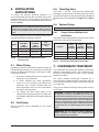
2
Revision 1 reects the following changes:
Removed California Proposition 65 warning on page 4.

3
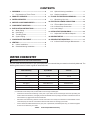
CONTENTS
1. WARNINGS .................................................................. 4
1.1. Pay Attention to These Terms .............................. 4
2. PRODUCT OVERVIEW ................................................. 5
3. WATER CHEMISTRY ................................................... 5
4. SHIPPED LOOSE COMPONENTS ............................ 5
5. COMPONENT LOCATIONS ....................................... 6
6. INSTALLATION INSTRUCTIONS ............................... 7
6.1. Water Piping ..............................................................7
6.2. Gas Piping ..................................................................7
6.3. Throttling Valve .........................................................7
6.4. System Piping ...........................................................7
7. CONDENSATE TREATMENT ..................................... 7
8. VENTING ....................................................................... 9
8.1. Indoor Installation ....................................................9
8.2. Standard Venting Installation ...............................9
8.3. Optional Venting Installation ................................ 9
8.4. Outdoor Installation ............................................. 11
9. FILLING THE SYSTEM/AIR REMOVAL ..................12
9.1. Winterizing Your Unit ........................................... 12
10. ELECTRICAL POWER CONNECTION ....................13
10.1. XTherm Boiler Connection ................................ 13
10.2. Indirect Pump Connection ................................ 13
10.3. Low Voltage ............................................................ 13
11. INITIAL START-UP SEQUENCE ...............................16
11.1. Adjust the Pool Indirect Setpoint ..................... 16
12. BOILER START-UP .....................................................16
13. SEQUENCE OF OPERATION ....................................17
13.1. Indirect Heat Exchanger Maintenance ......... 18
Water Chemistry Cupro Nickel Titanium
Water Temperature 68-104°F (20-40°C) 68-104°F (20-40°C)
pH 7.6-7.8 7.6-7.8
Total Alkalinity (ppm) 80-120 80-120
Calcium Hardness (ppm) 200-400 200-400
Salt (ppm) 4500 Maximum 6000 Maximum
Free Chlorine (ppm)* 2-3 2-3
Total Dissolved Solids (ppm) 3000 Maximum** 10000 Maximum
*Free Chlorine MUST NOT EXCEED 5 ppm!
**In saltwater chlorinated pools, the total TDS can be as high as 6000 ppm.
• Occasional chemical shock dosing of the pool or spa water should not damage the heater providing the
water is balanced. However, it is highly recommended that the heat pump pool heater is isolated via shut off
valves before any aggressive chemical treatment.
• Automatic chemical dosing devices and salt chlorinators are usually more efficient in heated water. Unless
controlled, they can lead to an excessive chlorine level which can damage your heater.
• Further advice should be obtained from your pool or spa builder, accredited pool shop, or chemical supplier
for the correct levels for your water.
Table A. Pool and Spa Water Chemistry
WATER CHEMISTRY
AA
CAUTION: Corrosive water voids all warranties
For your health and the protection of your pool equipment, it is essential that your water be chemically balanced. The
following levels must be used as a guide for balanced water.

4
AA
DANGER: Make sure the gas on which the heater will
operate is the same type as that specied on the heater
rating plate.
AA
WARNING: Do not use this heater if any part has
been under water. Immediately call a qualied service
technician to inspect the heater and to replace any part
of the control system and any gas control which has been
under water.
AA
WARNING: To minimize the possibility of improper
operation, serious personal injury, re, or damage to the
heater:
• Always keep the area around the heater free of
combustible materials, gasoline, and other ammable
liquids and vapors.
• Heater should never be covered or have any blockage
to the ow of fresh air to the heater.
AA
WARNING: Risk of electrical shock. More than one
disconnect switch may be required to de-energize the
equipment before servicing.
AA
WARNING: Should overheating occur or the gas
supply valve fail to shut, do not turn o or disconnect the
electrical supply to the heater. Instead, shut o the gas
supply at a location external to the heater.
AA
CAUTION: If this heater is to be installed above
radiation level, it must be provided with a low water cut-
o device at the time of heater installation.
AA
CAUTION: If this heater is to be installed in a negative
or positive pressure equipment room, there are special
installation requirements. Consult factory for details.
AA
WARNING: Both natural gas and propane have an
odorant added to aid in detecting a gas leak. Some people
may not physically be able to smell or recognize this
odorant. If you are unsure or unfamiliar with the smell
of natural gas or propane, ask your local gas supplier.
Other conditions, such as “odorant fade,” which causes
the odorant to diminish in intensity, can also hide,
camouage, or otherwise make detecting a gas leak by
smell more dicult.
AA
WARNING: UL-recognized fuel gas detectors are
recommended in all enclosed propane and natural gas
applications wherein there is a potential for an explosive
mixture of fuel gas to accumulate and their installation
should be in accordance with the detector manufacturer’s
recommendations and/or local laws, rules, regulations,
or customs.
1. WARNINGS
1.1. Pay Attention to These Terms
AA
DANGER
Indicates the presence of immediate hazards which will cause severe personal injury, death or substantial
property damage if ignored.
AA
WARNING
Indicates the presence of hazards or unsafe practices which could cause severe personal injury, death or
substantial property damage if ignored.
AA
CAUTION
Indicates the presence of hazards or unsafe practices which could cause minor personal injury or product or
property damage if ignored.
CAUTION
CAUTION used without the warning alert symbol indicates a potentially hazardous condition which could cause
minor personal injury or product or property damage if ignored.
NOTE
Indicates special instructions on installation, operation, or maintenance which are important but not related to
personal injury hazards.

5
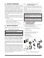
2. PRODUCT OVERVIEW
Raypak Professional Indirect Pool Heaters are factory
assembled and plumbed on a prefabricated skid using
our ultra-high-eciency XTherm boiler driving a highly
ecient shell and tube indirect heat exchanger(s).
The indirect heat exchanger keeps the XTherm boiler
safe from corrosive pool water (low pH or high chlorine
levels) by separating the boiler water from the pool water.
The standard conguration utilizes a highly corrosion
resistant Cupro-Nickel indirect heat exchanger, with an
option to upgrade to Titanium for the ultimate in corrosion
resistance.
The system arrives completely assembled, just connect,
ll, and ip the switch! No onsite soldering or assembly
needed. Easy to install and commission, the system comes
standard with:
• 7” touchscreen display
• Raypak’s Versa IC™ control system, full diagnostics,
history, and Modbus RTU BMS port
• PVC vent connections - economical to vent
• Full electronic load tracking with 7:1 turndown
3. WATER CHEMISTRY
Refer to the Water Chemistry Table A on page 3 of this
manual.
3.1.1. Pool/Spa Water Chemistry
AA
CAUTION: Corrosive water can cause unwarrantable
damage to the indirect heat exchanger.
NOTE: Chemical imbalance can cause severe damage to
your indirect heat exchanger and associated equipment.
Chemical imbalance can cause severe damage to the
indirect heat exchanger and associated equipment.
Maintain the water chemistry according to the Table A
on page 3. Indirect heat exchanger damage resulting
from chemical imbalance is not covered by the warranty.
For your health and the protection of your pool equipment,
it is essential that your water be chemically balanced. The
following levels must be used as a guide for balanced
water.
Occasional chemical shock dosing of the pool or spa
should not damage the indirect heat exchanger providing
the water is balanced. Automatic chemical dosing devices
and salt chlorinators are usually more ecient in heated
water. If not controlled, they can lead to high chemical
levels which can damage your indirect heat exchanger.
Further advice should be obtained from your pool or spa
builder, accredited pool shop, or chemical supplier for the
correct levels for your water.
3.1.2. Automatic Chlorinators and
Chemical Feeders
All chemicals must be introduced downstream of the
indirect heat exchanger and completely diluted into the
water before being circulated through the indirect heat
exchanger.
Chlorinators must feed downstream of the indirect heat
exchanger and have an anti-siphoning device or check
valve to prevent chemical back-up into the indirect heat
exchanger when the pool ltration pump is shut o.
AA
CAUTION: High chemical concentrations from feeders
that are out of adjustment will cause rapid corrosion of
the indirect heat exchanger. Such damage is not covered
under the warranty.
CAUTION: Failure of a indirect heat exchanger due to lime
scale build-up on the heating surface, low pH, or other
chemical imbalance is not covered under the warranty.
4. SHIPPED LOOSE
COMPONENTS
These items are shipped inside a box in the carton with
the Professional Indirect Pool Heater:
1. Vent Termination Cap Vertical/Horizontal
2. Flue Exhaust Termination Adapter for PVC Venting
3. Air Intake Collar
4. Air Intake Cover Panel
5. Indirect Plumbing Assy CPVC (2005A only)
6. Gasket ANSI Flange 4" (2005A only)
7. Vent Group PVC
8. Clamp, Vent Support
9. PVC Coupling 3/4" FNPT
3
1
2
5
6
4
7
9
8
Figure 1. Shipped Loose Components

6
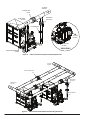
F10529
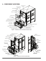
BOILER POWER
CONNECTION
PRESSURE RELIEF
VALVE
EXPANSION TANK
INDIRECT FLOW
SWITCH
INDIRECT JUNCTION BOX
(PUMP POWER CONNECTION)
POOL OR SPA WATER INLET
INDIRECT HEAT EXCHANGER
CONDENSATE NEUTRALIZER
CONDENSATE TRAP
PVC VENT (SHIPPED LOOSE)
INDIRECT WATER SENSOR
POOL OR SPA WATER OUTLET
INDIRECT PUMP
MANUAL AIR BLEEDER
VALVE
POOL WATER
TEMP SENSOR
POOL WATER TEMP LIMIT
COMBUSTION AIR
INLET
TEMP AND PRESSURE
GAUGE
DRAIN PLUG
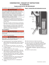
5. COMPONENT LOCATIONS
Figure 2. Component Locations for Models 1005A and 1505A
INDIRECT
JUNCTION BOX
INDIRECT
FLOW SWITCH
POOL WATER
TEMP SENSOR
CONDENSATE
NEUTRALIZER
INDIRECT
WATER SENSOR
BOILER POWER
PRESSURE RELIEF
VALVE
MANUAL AIR BLEED
VALVE
COMBUSTION AIR INLET
F10534
EXPANSION TANK
POOL AND SPA
WATER INLET
INDIRECT HEAT
EXCHANGER
PVC VENT
INDIRECT
PUMP
CONDENSATE TRAP
POOL WATER
TEMP LIMIT
MAKE-UP
WATER CONNECTION
INDIRECT HEAT
EXCHANGER
DRAIN PLUG
DRAIN PLUG
POOL AND SPA
WATER OUTLET
TEMP AND PRESSURE
GAUGE
Figure 3. Component Locations for Model 2005A

7
6.3. Throttling Valve
A ∆T of 8°F – 10°F (4°C – 5°C) across the indirect heat
exchanger is recommended. Throttling valves are used to
set the ow through the indirect heat exchanger. (Standard
buttery valves are acceptable.) See Figure 4 and Figure
5.
6.4. System Piping
NOTE: System piping provided by others.
6.4.1. Single Unit and Multiple Unit
Installation
Total system ow must be greater than the recommended
water ow to the indirect heat exchanger.
Example
Case 1
(1005A)
GPM (lpm)
Case 2
(1505A)
GPM (lpm)
Case 3
(2005A)
GPM (lpm)
(a) Total Sys Flow 300 (1136) 500 (1893) 600 (2271)
(b) Heater Flow 240 (908) 360 (1363) 480 (1817)
(c) Bypass Flow 60 (227) 140 (530) 120 (454)
Table C. Recommended Pool Water Flow Examples
7. CONDENSATE TREATMENT
The condensate must be drained properly to protect the
appliance and drainage system. The condensate from
the boiler condensate drain is acidic. Its pH is typically
between 3.2 and 4.5.
The factory installed Condensate Treatment Kit is
connected to the condensate drain of the boiler and vent
tee and contains treatment media to raise the pH level of
the condensate.
The pH of the effluent entering a sanitary drain must be
5.0 or higher.
AA
CAUTION: In general, the condensate piping from
the appliance must have a downward slope of 1/4" per
horizontal foot. Condensate drain traps must be primed
with water to prevent gas ue leaks. Treatment kits should
be checked at least once per year. To ensure the pH of the
euent is 5.0 or higher, the media should be replenished
as necessary. When replacing the media, they should be
no smaller than 3/4" to avoid blockage in the condensate
piping.
AA
WARNING: Do not install the heater outdoors if
freezing conditions are typical. The condensate will
freeze and back up the ue system.
6. INSTALLATION
INSTRUCTIONS
To achieve the optimum operating eciency it is
recommended that you keep the pool water ow of each
appliance within plus or minus 5 gallons per minute (18
liters per minute) of the recommended pool water ow as
stated in Table B.
CAUTION: Excessive temperature differential across the
indirect heat exchanger may result in short cycling of
the boiler and possible lockout on the Pool Water Temp
Limit.
Low ow through the indirect heat exchanger will result in
elevated temperatures supplied to the pool.
Model
Recommended
Pool Water
Flow
GPM (lpm)
Maximum
Pool Water
Flow
GPM (lpm)
Pipe
Connection
Size
1005A 240 (908) 400 (1514) 4"
1505A 360 (1363) 600 (2271) 6"
2005A 480 (1817) 800 (3028) 6"
Table B. Recommended Pool Water Flow and Pipe
Connection Size
6.1. Water Piping
Pool/Spa connections to the indirect heat exchanger are
SCH 80 CPVC glue ttings. The connections from the eld
loop to the indirect heat exchanger may be done in CPVC
or PVC pipe as follow:
a. Pool water is designed to flow from right to left
standing in front of the boiler.
b. A factory installed pool water temperature
sensor is on the inlet side of the indirect heat
exchanger, and a factory installed fixed pool
water temperature limit is on the outlet side of
the indirect heat exchanger.
c. The supply and return water piping to the
indirect heat exchanger shall be no smaller than
4" for Model 1005A and 6" for Models 1505A and
2005A.
6.2. Gas Piping
See the XTherm manual (3400.552) for gas piping
information.

8
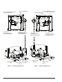
Figure 4. Indirect Pool Heater Single Unit Plumbing Schematic
Figure 5. Indirect Pool Heater Multiple Unit Plumbing Schematic
ISOLATION
VALVE (x2)
THROTTLING
VALVE
F10530
TO POOL
OR SPA
FROM POOL
OR SPA
FLOW METER
TO POOL
OR SPA
FROM POOL
OR SPA
2005A ONLY
TEMP AND PRESSURE
GAUGE
FROM POOL
OR SPA
TO POOL
OR SPA
ISOLATION
VALVE (x4)
FLOW METER
(x2)
THROTTLING VALVE
(x3)
F10531

9
8. VENTING
AA
CAUTION: Proper installation of ue venting is critical
for the safe and ecient operation of the heater.
NOTE: Raypak strongly recommends installing the vent
system before water piping. This will ensure that the
venting system and associated components will t into
the allotted space for proper operation.
For vent termination, see the XTherm manual (3400.552)
for detailed information.
8.1. Indoor Installation
CAUTION: Combustion air must not be contaminated by
corrosive chemical fumes which can damage the heater
and void the warranty.
For indoor installation, see the XTherm manual (3400.552)
for detailed information.
8.2. Standard Venting Installation
The unit as shipped is congured to have the vent system
routed to the left of the skid as viewed from the front
door of the boiler cabinet. This is accomplished using
the supplied PVC venting components included with the
system. These are to be oriented as shown in Figure 6.
1. First prepare the PVC flue outlet pipe at the rear of the
boiler and PVC elbow provided using an appropriate
PVC primer.
2. Using an appropriate PVC glue, assemble the elbow
to the PVC flue outlet pipe. The flue outlet pipe can
be rotated by loosening the clamp on the flue outlet
adapter inside the rear of the boiler cabinet for
alignment purposes.
3. Prepare the provided PVC flue tee assembly and
elbow from the previous step using an appropriate
PVC primer.
4. Using an appropriate PVC glue, assemble the
supplied PVC flue tee assembly to the PVC elbow
attached to the PVC flue outlet of the boiler and
orient as shown in Figure 6.
NOTE: The PVC ue pipe must rest on the ue support
brackets provided and mounted on the skid system to
allow for proper drainage of the condensate. Failure to
provide proper drainage can cause a non-warrantable
failure of the ue system.
5. Attach the hose from condensate trap to the barb
fitting on the vent tee with hose clamp.
6. With the PVC flue tee and associated components
installed per Figure 6 you are now ready to complete
the PVC vent system installation by connecting your
field supplied PVC pipe to the point of termination.
8.3. Optional Venting Installation
1. Identify three rubber hoses from the Standard
Venting Direction. See Figure 7.
a. XTherm condensate outlet to neutralizer.
b. Condensate trap tee connection to neutralizer
inlet, top connection.
c. Vent tee to condensate trap, bottom connection.
2. Detach all three hoses. Loosen neutralizer clamps,
then remove the neutralizer.
3. Remove the vent support bracket and the neutralizer
base mounting bracket and relocate as shown in
Figure 6 and
Figure 7.
4. Install the neutralizer in opposite direction as shown
in Figure 7.
5. Remove the 3/4" elbow from the boiler condensate
drain connection and attach the straight coupling
with the barb fitting from the 3/4" elbow.
6. Loosen retaining screws and rotate condensate trap
about 180 degrees using top connection as guide.
7. Cut hoses to fit and install as shown. Make sure hoses
do not kink.
8. Install vent elbow and the vent tee as shown in Figure
7.

10
Figure 6. Standard Venting Direction
VENT SUPPORT
BRACKET
NEUTRALIZER
OUTLET
CONDENSATE
TRAP
TOP VIEW
BOILER CONDENSATE
DRAIN
BOILER CONDENSATE OUTLET
TO NEUTRALIZER INLET
CONDENSATE TRAP
TO NEUTRALIZER INLET
TOP CONNECTION
VENT TEE TO
CONDENSATE TRAP
BOTTOM CONNECTION
F10535
Figure 7. Optional Venting Direction
NEUTRALIZER
OUTLET
CONDENSATE
TRAP
VENT SUPPORT
BRACKET
BOILER CONDENSATE
DRAIN
BOILER CONDENSATE OUTLET
TO NEUTRALIZER INLET
CONDENSATE TRAP
TO NEUTRALIZER INLET
TOP CONNECTION
VENT TEE TO
CONDENSATE TRAP
BOTTOM CONNECTION
TOP VIEW

11
Figure 8. Outdoor Installation
D-23 FLUE
SUPPORT
BRACKETS
D-15
PVC TO STAINLESS
ADAPTER
F10537
36" MIN
(914 mm)
8.4. Outdoor Installation
XTherm heaters are certified for outdoor operation in
non-freezing conditions only. Freezing conditions may
cause condensate to freeze in the condensate drain line
and trap, causing the unit to shut down due to a blocked
condensate drain. Additionally, components of the
condensate management system may be damaged by
the ice formation. Units installed in freezing climates for
seasonal use must be winterized to avoid freeze damage
to the heater.
Outdoor models must be vented with listed vent material
per the following instructions and installed with the
optional factory-supplied outdoor vent kit. A special vent
cap is provided in accordance with CSA requirements. It
must be installed directly on the vent pipe as illustrated
in Figure 8.
Care must be taken when locating the heater outdoors,
because the flue gases discharged from the vent cap
can condense as they leave the cap. Improper location
can result in damage to adjacent structures or building
finish. For maximum efficiency and safety, the following
precautions must be observed:
1. Outdoor models must be installed outdoors and
must use the outdoor vent cap available from the
manufacturer.
2. Periodically check venting system. The heater’s
venting areas must never be obstructed in any way
and minimum clearances must be observed to
prevent restriction of combustion and ventilation
air. Keep area clear and free of combustible and
flammable materials.
3. Do not locate adjacent to any window, door, walkway,
or gravity air intake. The vent must be located a
minimum of 4' (1.2 m) horizontally from such areas.
4. Install above grade level and above normal snow
levels.
5. Vent terminal must be at least 3' (1 m) above any
forced air inlet located within 10' (3 m).
6. Adjacent brick or masonry surfaces must be
protected with a rust-resistant sheet-metal plate.
NOTE: The vent cap must be furnished by the heater
manufacturer in accordance with its listing.
NOTE: Condensate can freeze on the vent cap. Frozen
condensate on the vent cap can result in a blocked ue
condition and non-warrantable failure. Condensate is
acidic and highly corrosive. Condensate must not be
allowed to freeze. Take appropriate measures.

12
9. FILLING THE SYSTEM/AIR
REMOVAL
The boiler is to be lled with clean and cool water by
connecting to the 3/4" make-up water valve adjacent to
the expansion tank.
Connect the water line/hose to the ll valve, open the
valve, and ll the boiler loop to an operating pressure of
15psi. See the temp and pressure gauge on the boiler
piping as shown in Figure 4.
Bleed the air out through manual bleed valve on the boiler
to indirect manifold above the expansion tank. It may take
several minutes for all the air to be evacuated from the
boiler and indirect piping. See Figure 2 and Figure 3.
Close the ll valve and make sure there is no leakage in the
system. The expansion tank is set at 20psi.
Fill pressure of less than 10psi will not close the water
pressure safety switch, which will prevent the system from
operating.
MAKE-UP WATER
MANUAL FILL
ISOLATION VALVE
(TYP)
PRESSURE RELIEF
VALVE
POOL WATER
TEMP SENSOR
POOL WATER
TEMP LIMIT
PVC VENT
CONNECTION
CONDENSATE
DRAIN
FLOW METER
BY OTHERS
TO POOL
POOL SYSTEM
PUMP
OR SPA
THROTTLING
VALVE
CHEMICAL
INSERTION POINT
2X 6"
PVC
2005A ONLY
FROM POOL
OR SPA
FILTER
COARSE
STRAINER
F10536
WATER FILL
VALVE
EXPANSION
TANK
MANUAL BLEED
VALVE
Figure 9. Recommended Plumbing Setup
NOTE: Unit is equipped with a water pressure safety
switch designed to disable the boiler and provide an
alarm output in the event of an indirect heat exchanger
failure.
9.1. Winterizing Your Unit
Units installed outdoors in freezing climate areas should
be shut down for the winter. To shut down the heater,
turn o the manual main gas valve and main gas shut-
o. Close isolation valves. Drain the XTherm boiler using
the hose bibs located on the bottom of both internal heat
exchangers. Disconnect the condensate hose from the
boiler and drain the condensate trap and Condensate
Treatment Kit. Drain the indirect heat exchanger(s) by
removing the drain plug(s) at the bottom of the aluminum
housing.
NOTE: There are 3 separate drains on the XTherm that
must ALL be drained to protect the boiler heat exchangers.
These are accessible by removing the lower front door
from the heater for the 2 primary drains and the right-rear
panel for the condensing heat exchanger drain. Drain any
piping of all water that may experience below-freezing
temperatures. Refer to the XTherm manual (3400.552).

13
10. ELECTRICAL POWER
CONNECTION
AA
WARNING: Electrical power connection must be
performed by qualied licensed electrician(s) for the
voltage being applied.
Model
Amp Draw** (120V)
Boiler †
Minimum
Breaker
Rating
Pump †
Minimum
Breaker
Rating
1005A 12** 20 10 15
1505A 12** 20 14 20
2005A 18** 25 17 25
† Separate power connections are factory supplied and separate supply breakers
must be eld supplied.
** Current draw is for boiler only (Supply breaker must have delayed trip).
Breakers must be motor rated.
Table D. Electrical Power and Breakers
10.1. XTherm Boiler Connection
For XTherm boiler connections, please refer to the XTherm
manual (3400.552) for location data for proper connection.
10.2. Indirect Pump Connection
The indirect heat exchanger has a dedicated, factory
mounted pump that requires a dedicated power circuit
per the ampacity and breaker Table D.
Power is to be brought into the indirect J-box using the
upper most electrical knockout via properly rated conduit
and connected directly to the indirect pump contact or
opposite the factory pump wiring as shown in Figure 10.
Use caution when connecting solid core conductors as
BOILER POWER
INDIRECT
PUMP
POWER
this can put strain onto the contactor connections and
may damage the contactor.
The indirect pump is shipped factory wired and congured
for 115V/1PH power but can be eld congured for
230V/1PH if so desired. Follow the instructions on the
pump motor cover to convert the motor from 115V/1PH to
230V/1PH before turning power on to the unit to prevent
possible damage.
10.3. Low Voltage
10.3.1. System Interlock (Indirect DHW
Override)
Contact closure is required between terminals 10 and 12
on the eld wiring terminal block to enable the system to
run. See Figure 12.
This contact MUST BE interlocked with the ltration pump
or a fault may occur.
10.3.2. External Interlock
To be used in conjunction with an optional system fault
switch or extractor fan, combustion air lubber, etc.
Use stranded conductor copper wire. Contact closure is
required between terminals 17 and 18 on the eld wiring
terminal block. Remove factory jumper when connecting
eld installed devices such as a system ow switch, or a
damper proving switch. See Figure 12.
10.3.3. Fan Damper (Optional)
Used to enable fan or motorized damper. Connection is
pilot duty, dry contact.
10.3.4. Alarm (Optional)
Connection is pilot duty, dry contact and is closed to
indicate an alarm connection exist.
Figure 10. Inside Junction Box
Figure 11. Indirect Pump Power
INDIRECT PUMP
POWER
SYSTEM
FLOW
SWITCH
INDIRECT PUMP
(GND)
INDIRECT PUMP
(COM)
INDIRECT PUMP
(HOT)
SYSTEM
FLOW SWITCH
INTERLOCK
F10524

14
1 2 3
24VAC
CWP
4 5
6 7
8 9
24
23
22
21
20
19
18
17
16
15
14
13
12
11
10
USE COPPER CONDUCTORS ONLY
CWP
0 - 10 VDC
EMS
INPUT
JUMPER WHEN
NOT USED
ALARM
DRY
CONTACTS
120V
EXTERNAL
SAFETY
VALV E
FAN/DAMPER
DRY
CONTACTS
EXTERNAL
INTERLOCK
SYSTEM
SENSOR
OUTDOOR
SENSOR
INDIRECT
DHW
SENSOR
TEMP TO
INDIRECT
SENSOR
JUMPER 11 & 12
WHEN NOT USED
ENABLE/
DISABLE
INDIRECT
DHW OVERIDE
FIELD WIRING
TERMINAL BLOCKS
FACTORY WIRING
INDIRECT
OVERRIDE
N/A N/AN/A
N/A FACTORY
SYSTEM
SENSOR
INDIRECT
DHW SENSOR
EXTERNAL INTERLOCK
(SYSTEM FLOW SWITCH)
FAN/DAMPER
DRY CONTACTS
ALARM
DRY CONTACTS
O
Figure 12. Low Voltage Terminal Block
Figure 13. Indirect Pool Heater Wiring Diagram

15
For Reference Only
Figure 14. Indirect Pool Heater Wiring Diagram

16
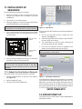
Figure 16. Menu Screen
Once in the POOL SETTINGS screen set the Pool Setpoint,
as follows:
4. Use the up and down arrows to adjust the Pool
Setpoint. See Figure 17.
5. After setting the desired Pool Setpoint, press the SET
button to apply the changes
6. The confirmation bar will turn green showing that
the value entered has been applied.
7. Once the Pool Setpoint values are applied to the
system, the confirmation bar will turn green.
NOTE: The minimum setpoint temperature is 50°F (10°C)
and the maximum is 104°F (40°C).
Figure 17. Pool Setpoint Adjustment
Pool Dierential is subtractive to the setpoint. For example,
in the case of a Pool Setpoint of 80°F (27°C) with a 2°F (1°C)
dierential, the control will energize the heater when the
pool temperature drops to 78°F (26°C) and then will shut
the heater o at 80°F (27°C). The Pool Dierential defaults
to 2°F (1°C) with a range of 2°F (1°C) to 5°F (3°C).
SETUP COMPLETE!
12. BOILER START-UP
For boiler start-up, see the XTherm manual (3400.552) for
detailed information.
11. INITIAL START-UP
SEQUENCE
Do the initial start-up sequence, as follows:
1. Verify pool filtration system is operational and flow
through the indirect heat exchanger has been
established.
2. Turn power on to the boiler pump.
3. Verify gas supply is on to the unit. Refer to the XTherm
manual (3400.552) for gas supply data.
NOTE: Conrm that the DIP Switch #7 on the VERSA
control board is in the ON position for proper operation.
4. Turn on boiler power at the front panel rocker switch.
Allow controls to load. This may take several minutes
on initial setup.
HIGH VOLTAGE
SWITCH
LOW VOLTAGE
SWITCH
Figure 15. Front Panel Voltage Switches
5. Once you reach the default screen you can set up the
desired Pool Setpoint and Differential.
NOTE: In the event of a water pressure fault, conrm
that boiler water loop pressure exceeds 10 PSI. Water
pressure of less than 10 PSI will prevent the system from
operating.
11.1. Adjust the Pool Indirect Setpoint
Adjust the XTherm Pool Indirect Setpoint, as follows:
1. Press the MENU button to open the menu options.
See Figure 16.
2. Select the ADJUST menu.
3. Press the POOL SETTINGS button.

17
15. The voltage level of the 24VAC supply input is
confirmed to be above 18VAC – if not, a Low Voltage
fault will be recorded and the heater will go into a
soft lockout condition until the voltage rises above
18VAC consistently.
16. If all checks have passed, the system proceeds to
ignition. Safeties include water pressure safety switch,
condensate switch, low water cut-off, temperature
high limits indirect and boiler temperature limit,
switches, indirect flow switch, boiler, and system
flow switch (optional).
17. The PIM re-initializes the ignition counter to the
configured number of trials (typically 1 or 3).
18. The Hi Limit sensor is confirmed to read below the
boiler Hi Limit Setpoint.
19. The blower light-off RPM speed is verified.
20. The gas valve relay contacts are verified open – if
closed, a fault code will be issued and the boiler will
post-purge and go into a hard lockout condition.
21. The XTherm is equipped with a Hot Surface Igniter
(HSI):
a. The control turns on the HSI and the HSI proving
current is verified to be above the configured
value.
b. The configured heat-up delay takes place to allow
the HSI element to reach ignition temperature.
c. The gas valve output is energized for the trial for-
ignition time to light the burner.
d. The HSI is de-energized during the last second
of the trial-for-ignition period to sense for the
burner flame.
e. The flame sense is checked for successful
lighting of the burner. If a valid flame is detected,
the main gas valve, operating pumps and blower
relay remain energized and the PIM proceeds to
the Heating mode.
22. If flame is not detected during the trial-for-ignition
period, the gas valve output is disabled immediately
and the blower goes to a post-purge.
23. On single trial-for-ignition models, the PIM enters
ignition lockout and the LED on the PIM indicates the
fault code for ignition lockout. The VERSA IC display
will also state Ignition Lockout.
24. On multi-trial-for-ignition models, the control goes
through an inter-purge delay before additional
ignition attempts are started. If no flame is detected
after the final trial-for-ignition, the PIM enters ignition
lockout and the LED on the PIM indicates the fault
code for ignition lockout. The VERSA IC display will
also state Ignition Lockout.
13. SEQUENCE OF OPERATION
1. Upon initial application of 24VAC power, the PIM
resets with all outputs in the “OFF” state.
2. The PIM and VERSA IC perform a processor and
memory self-test to ensure proper operation.
3. The PIM confirms the presence of a valid ID card
which matches the configuration stored in memory
at the factory. If a valid ID card is NOT present, the
PIM generates a diagnostic fault and will shut down
waiting for this fault to be addressed.
4. The PIM reads the DIP switch settings and configures
itself for the desired operation. PIM DIP 3 must be
ON, which indicates primary/secondary and uses a
boiler pump.
5. The VERSA board reads the DIP switch settings
and configures itself for the desired operation.
VERSA board DIP 3 must be ON to allow Cold Water
Protection operation, VERSA board DIP 7 must be
ON indicating the presence of the external indirect
heat exchanger.
6. The PIM scans the FTbus communications for the
VERSA IC and if found, system operation is controlled
by the VERSA IC Control.
7. Non-volatile memory is checked for any active
lockout conditions. If any exist, they must be
addressed before the PIM will allow a new trial for
ignition to start.
8. The PIM continually monitors the flame status to
ensure that no flame is present during standby. If an
erroneous flame is detected, the PIM generates a
False Flame error fault.
9. A call-for-heat is initiated by a heat demand (contact
closure) on the field wiring terminals 10 and 12,
assuming that the VERSA IC sees the indirect pool
water temperature sensor temperature is below Pool
Setpoint.
10. The PIM initiates a trial for ignition counter to the
programmed number of trials for ignition (1 or
multiple) and proceeds to Pump Purge mode.
11. The VERSA IC will turn on the boiler pump, system
pump, and Indirect pump as necessary to address
the call-for-heat. The boiler will proceed through its
pre-purge period before the control will move into a
Trial for Ignition (TFI).
12. The VERSA board and PIM check the safety circuit
and will stop from going into a trial for ignition if any
of the safety devices is in an error/fault condition.
13. The blower is energized and set to pre-purge speed.
14. Once the blower speed is acknowledged as operating
at the pre-purge speed by the tachometer output,
the blower proceeds to pre-purge for the specified
duration.

18
25. Once flame has been proven and rectified, the unit
will release to full modulation.
26. The unit will modulate to achieve indirect Pool
Setpoint, and maintain water inlet temperature with
the built in twin injector pumps.
13.1. Indirect Heat Exchanger
Maintenance
The indirect heat exchanger must be regularly inspected
and cleaned as needed. A fouled heat exchanger can have
a major impact on system eciency. Problems typically
occur due to scale buildup and particulate deposits due to
low ow. This can result in loss of unit performance due to
heat transfer problems and tube failure.
F10523
BOILER OUT
BOILER IN
FROM POOL
TO POOL
MOUNTING BRACKETS
CPVC FLANGE
POOL WATER TEMP
SENSOR
POOL WATER TEMP
LIMIT
DRAIN PLUG
Figure 18. Indirect Heat Exchanger

19
NOTES

www.raypak.com
Raypak, Inc., 2151 Eastman Avenue, Oxnard, CA 93030 (805) 278-5300 Fax (805) 278-5468
Litho in U.S.A.
-
 1
1
-
 2
2
-
 3
3
-
 4
4
-
 5
5
-
 6
6
-
 7
7
-
 8
8
-
 9
9
-
 10
10
-
 11
11
-
 12
12
-
 13
13
-
 14
14
-
 15
15
-
 16
16
-
 17
17
-
 18
18
-
 19
19
-
 20
20


Raypak PROFESSIONAL INDIRECT SUPPLEMENTAL Operating instructions
- Category
- Above ground pool accessories
- Type
- Operating instructions
Ask a question and I''ll find the answer in the document
Finding information in a document is now easier with AI
Related papers
-
Raypak 259 & 409 Operating instructions
-
-
-
-
Raypak 408 Installation & Operating Instructions Manual
-
-
-
-
-
Raypak ELS-R-0024-4-TI User manual
Other documents
-
Rheem GHE100SS-400A User manual
-
Weil-McLain Weil McLain Maxi-Flo Pool Heater WMPH-135, 200, 260 & 400 Operating instructions
-
 UTICA BOILERS UB90-200 Installation & Operation Manual
-
-
EZ-FLO 98643 Installation guide
-
Balboa AIR BLOWER Operating instructions
-
American Standard 2848.403.ALW-PC Operating instructions
-
Pentair MegaTherm MT 4050 User manual
-
Rheem TWPH-4550EHT10 Owner's manual
-
HTP EFT-399PU Installation guide
