Page is loading ...

For questions or help with this product contact Tech Support at (570) 546-9663 or techsupport@grizzly.com
MODEL T30027
POCKET HOLE GUIDE
INSTRUCTIONS
COPYRIGHT © MARCH, 2019 BY GRIZZLY INDUSTRIAL, INC.
NO PORTION OF THIS MANUAL MAY BE REPRODUCED IN ANY SHAPE
OR FORM WITHOUT THE WRITTEN APPROVAL OF GRIZZLY INDUSTRIAL, INC.
(FOR MODELS MFD. SINCE 02/19) #RS20318 PRINTED IN TAIWAN
Introduction
The T30027 Pocket Hole Guide is a jig for creating
quick, incredibly strong joints. It can be attached
to a workpiece or mounted to a bench. Including
everything needed to get started, this jig creates
post and rail, curve, edge-to-edge, mitered frame
corner, square corner, and T joints. The T30027
comes fully assembled.
V1.03.19
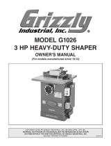
Workpiece Thickness
The optimal material thickness for the T30027
Pocket Hole Guide is
3
⁄4". This allows screws to
exit at the center point of the workpiece. It works
with a workpiece thickness range of
5
⁄8" to 1
1
⁄2". To
create a strong joint, thicker material may require
pocket holes on both sides.
3/4"
OptimalMinimum
Center Point
Maximum
Figure 2. Range of acceptable workpiece
thickness.
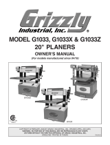
Identification
Figure 3. Pocket Hole Guide main components.
Scale
Clamp
Column
Pin
Drill Bit
Bushing
ColumnClamp
Handle
Description Qty
A. Step Drill Bit
3
⁄8" .......................................... 1
B.
Stop Collar
3
⁄8" ............................................ 1
C.
Square Drive Bits (#2 x 75, 150mm) .......... 2
D.
Hex Wrenches (2.5, 3, 4mm)...................... 3
E.
Pocket Hole Screws 1
1
⁄4" (Not Shown) ... 100
F.
Pocket Hole Guide (Not Shown) ................ 1
Inventory
Specifications
Step Drill Bit Size .............................................
3
⁄8"
Optimal Workpiece Thickness
.........................
3
⁄4"
Workpiece Thickness Range
..................
5
⁄8"–1
1
⁄2"
Pocket Hole Center Spacing Range
........1
1
⁄8"–3"
Figure 1. Loose inventory.
A B C D
5
⁄8"
1
1
⁄2"
3
⁄4"

-2-
T30027 Pocket Hole Guide (Mfd. 2/19+)
Mounting
The most common way to mount the jig is secur-
ing it to a bench. It can also be clamped directly
to the workpiece. The built-in clamp allows for
hands-free drilling during either procedure.
To mount guide to bench:
1. Secure jig to bench using (3) wood screws
(not included).
2.
For additional workpiece support, attach
scrap boards
7
⁄16" thick flush with sides of jig
bed, as shown in Figure 4.
Figure 4. Jig mounted to bench.
To clamp guide to workpiece:
1. Use clamp handle to clamp jig directly to
workpiece, as shown in Figure 5.
Figure 5. Jig mounted to workpiece.
Scrap Boards
x 3
Clamp
Handle
Jig Bed
Operating Adjustments
The rubber foot on the clamp has a threaded shaft
and jam nut that can be used to adjust clamping
force against the workpiece (see Figure 6).
To move clamping mechanism:
1. Remove (4) button head cap screws that
secure clamp mechanism to jig bed (see
Figure 7).
2. Align clamp mechanism with threaded holes
in jig bed (see Figure 7).
Figure 6. Adjustable clamping components.
Rubber Foot
Jam
Nut
3. Re-attach clamp mechanism with (4) button
head cap screws removed in Step 1.
Figure 7. Clamp placement on jig bed for thicker
workpieces.
Threaded
Hole
x 4
The clamp mechanism can be moved on the jig
bed to secure workpiece material up to 1
1
⁄2" thick.

T30027 Pocket Hole Guide (Mfd. 2/19+)
-3-
Drill Bit Depth
When attached to the step drill bit, the stop col-
lar is used to control pocket depth. This also
determines the length of screw that will join the
workpieces together.
To adjust stop collar:
1. Remove workpiece from jig, and ensure stop
collar set screw is flush with inside of stop col-
lar using 2.5mm hex wrench (see Figure 8).
Figure 8. Set screw in stop collar.
Set Screw
Stop
Collar
Hex Wrench
4. Loosen set screw just enough to set step drill
bit tip
1
⁄8" from jig bed, as shown in Figure 11.
Figure 11. Step drill bit
1
⁄8" from jig bed.
Preparing Drill Bit Bushings
Before using the jig on a workpiece, create mul-
tiple pocket holes on a scrap board. This sets the
bushings flush with the columns and smooths
uneven surfaces between the stop collar and
drill bit bushings. This results in a consistent and
accurate drilling depth for this jig (see Figure 12).
After
Scrap
Board
Before
Receiving
Board
Figure 12. Before and after preparing bushings.
5.
Tighten set screw.
Note: The stop collar is now set for the
included 1
1
⁄4" pocket hole screws. Adjusting
the collar up or down the step drill bit will
allow for deeper or shallower pockets and
determine fastener length.
Eye injury hazard! Always
wear safety glasses when
using this tool.
Step Drill Bit
Set
Screw
Jig
Bed
1
⁄8"
2. Slide stop collar onto step drill bit and lightly
tighten 2
3
⁄8" from end of shank (see Figure 9).
Figure 9. Stop collar on step drill bit.
2
3
⁄8"
3.
Insert step drill bit into drill bit bushing, allow-
ing stop collar to rest on top (see Figure 10).
Figure 10. Stop collar resting on drill bit bushing.
Drill Bit
Bushing
Column
Tip
Stop
Collar
Shank

-4-
T30027 Pocket Hole Guide (Mfd. 2/19+)
Adjusting Pocket Hole Spacing
The Pocket Hole Guide can provide approxi-
mately 1
1
⁄8" to 3" of spacing between pocket hole
centers while clamped in a single position.
2.
Move columns to desired measurement, as
referenced on the scale shown in Figure 14.
To adjust spacing:
1. With 4mm hex wrench, loosen button head
cap screw beneath scale until columns slide
freely on column pin (see Figure 13).
Figure 13. Button head cap screw location.
Button Head Cap Screw
Column
Pin
Figure 14. Inside of column against scale.
Inside
Columns
Scale
3. Tighten button head cap screw.
/