Page is loading ...

Operating Instructions
Capacitive rod electrode for level
detection
VEGACAP 27
Relay (DPDT)
Document ID: 33758

2
Contents
VEGACAP 27 • Relay (DPDT)
33758-EN-170503
Contents
1 About this document
1.1 Function ........................................................................................................................... 4
1.2 Target group ..................................................................................................................... 4
1.3 Symbols used................................................................................................................... 4
2 For your safety
2.1 Authorised personnel ....................................................................................................... 5
2.2 Appropriate use ................................................................................................................ 5
2.3 Warning about incorrect use ............................................................................................. 5
2.4 General safety instructions ............................................................................................... 5
2.5 Safety label on the instrument .......................................................................................... 6
2.6 EU conformity ................................................................................................................... 6
2.7 Installation and operation in the USA and Canada ........................................................... 6
2.8 Safety instructions for Ex areas ........................................................................................ 6
2.9 Environmental instructions ............................................................................................... 6
3 Product description
3.1 Conguration .................................................................................................................... 7
3.2 Principle of operation........................................................................................................ 8
3.3 Adjustment ....................................................................................................................... 8
3.4 Packaging, transport and storage ..................................................................................... 9
4 Mounting
4.1 General instructions ....................................................................................................... 10
4.2 Mounting instructions ..................................................................................................... 11
5 Connecting to power supply
5.1 Preparing the connection ............................................................................................... 13
5.2 Wiring plan, single chamber housing.............................................................................. 13
6 Setup
6.1 General information ........................................................................................................ 15
6.2 Adjustment elements ...................................................................................................... 15
6.3 Function table ................................................................................................................. 17
7 Maintenanceandfaultrectication
7.1 Maintenance .................................................................................................................. 19
7.2 Rectify faults ................................................................................................................... 19
7.3 Exchanging the electronics module ................................................................................ 21
7.4 How to proceed if a repair is necessary .......................................................................... 22
8 Dismount
8.1 Dismounting steps.......................................................................................................... 23
8.2 Disposal ......................................................................................................................... 23
9 Supplement
9.1 Technical data ................................................................................................................ 24
9.2 Dimensions .................................................................................................................... 28
9.3 Industrial property rights ................................................................................................. 30
9.4 Trademark ...................................................................................................................... 30

3
Contents
VEGACAP 27 • Relay (DPDT)
33758-EN-170503
Supplementary documentation
Information:
Supplementary documents appropriate to the ordered version come
withthedelivery.Youcanndthemlistedinchapter"Product descrip-
tion".
Instructions manuals for accessories and replacement parts
Tip:
ToensurereliablesetupandoperationofyourVEGACAP27,weoer
accessories and replacement parts. The corresponding documenta-
tions are:
•
33761 - Oscillator CAP E31R
Editing status: 2017-04-24

4
1 About this document
VEGACAP 27 • Relay (DPDT)
33758-EN-170503
1 About this document
1.1 Function
This operating instructions manual provides all the information you
need for mounting, connection and setup of the instrument. Further-
morethereareimportantinstructionsformaintenance,faultrectica-
tion, the exchange of parts and the safety of the user. Please read this
information before putting the instrument into operation and keep this
manual accessible in the immediate vicinity of the device.
1.2 Target group
This operating instructions manual is directed to trained specialist
personnel. The contents of this manual should be made available to
these personnel and put into practice by them.
1.3 Symbols used
Information, tip, note
This symbol indicates helpful additional information.
Caution: If this warning is ignored, faults or malfunctions can result.
Warning: If this warning is ignored, injury to persons and/or serious
damage to the instrument can result.
Danger: If this warning is ignored, serious injury to persons and/or
destruction of the instrument can result.
Ex applications
This symbol indicates special instructions for Ex applications.
SIL applications
This symbol indicates instructions for functional safety which must be
taken into account particularly for safety-relevant applications.
•
List
The dot set in front indicates a list with no implied sequence.
→
Action
This arrow indicates a single action.
1 Sequence of actions
Numbers set in front indicate successive steps in a procedure.
Battery disposal
This symbol indicates special information about the disposal of bat-
teries and accumulators.

5
2 For your safety
VEGACAP 27 • Relay (DPDT)
33758-EN-170503
2 For your safety
2.1 Authorised personnel
All operations described in this operating instructions manual must
be carried out only by trained specialist personnel authorised by the
plant operator.
During work on and with the device the required personal protective
equipment must always be worn.
2.2 Appropriate use
The VEGACAP 27 is a sensor for point level detection.
Youcannddetailedinformationabouttheareaofapplicationin
chapter"Product description".
Operational reliability is ensured only if the instrument is properly
usedaccordingtothespecicationsintheoperatinginstructions
manual as well as possible supplementary instructions.
For safety and warranty reasons, any invasive work on the device
beyond that described in the operating instructions manual may be
carried out only by personnel authorised by the manufacturer. Arbi-
traryconversionsormodicationsareexplicitlyforbidden.
2.3 Warning about incorrect use
Inappropriate or incorrect use of the instrument can give rise to
application-specichazards,e.g.vesseloverllordamagetosystem
components through incorrect mounting or adjustment. Thus dam-
age to property, to persons or environmental contamination can be
caused. Also the protective characteristics of the instrument can be
inuenced.
2.4 General safety instructions
This is a state-of-the-art instrument complying with all prevailing
regulations and directives. The instrument must only be operated in a
technicallyawlessandreliablecondition.Theoperatorisresponsi-
ble for the trouble-free operation of the instrument. When measuring
aggressive or corrosive media where a malfunction of the instrument
can cause a danger, the operator has to convince himself on the cor-
rect function of the instrument by taking suitable measures.
During the entire duration of use, the user is obliged to determine the
compliance of the necessary occupational safety measures with the
current valid rules and regulations and also take note of new regula-
tions.
The safety instructions in this operating instructions manual, the na-
tional installation standards as well as the valid safety regulations and
accident prevention rules must be observed by the user.
For safety and warranty reasons, any invasive work on the device
beyond that described in the operating instructions manual may be
carried out only by personnel authorised by the manufacturer. Arbi-
traryconversionsormodicationsareexplicitlyforbidden.Forsafety

6
2 For your safety
VEGACAP 27 • Relay (DPDT)
33758-EN-170503
reasons,onlytheaccessoryspeciedbythemanufacturermustbe
used.
To avoid any danger, the safety approval markings and safety tips on
the device must also be observed and their meaning looked up in this
operating instructions manual.
2.5 Safety label on the instrument
The safety approval markings and safety tips on the device must be
observed.
2.6 EU conformity
ThedevicefullsthelegalrequirementsoftheapplicableEUdirec-
tives.ByaxingtheCEmarking,weconrmsuccessfultestingofthe
product.
YoucanndtheCECerticateofConformityinthedownloadsection
under"www.vega.com".
2.7 Installation and operation in the USA and
Canada
This information is only valid for USA and Canada. Hence the follow-
ing text is only available in the English language.
Installations in the US shall comply with the relevant requirements of
the National Electrical Code (ANSI/NFPA 70).
Installations in Canada shall comply with the relevant requirements of
the Canadian Electrical Code
2.8 Safety instructions for Ex areas
PleasenotetheEx-specicsafetyinformationforinstallationandop-
eration in Ex areas. These safety instructions are part of the operating
instructions manual and come with the Ex-approved instruments.
2.9 Environmental instructions
Protection of the environment is one of our most important duties.
That is why we have introduced an environment management system
with the goal of continuously improving company environmental pro-
tection.Theenvironmentmanagementsystemiscertiedaccording
to DIN EN ISO 14001.
Pleasehelpusfullthisobligationbyobservingtheenvironmental
instructions in this manual:
•
Chapter"Packaging, transport and storage"
•
Chapter"Disposal"

7
3 Product description
VEGACAP 27 • Relay (DPDT)
33758-EN-170503
3 Product description
3.1 Conguration
The scope of delivery encompasses:
•
Level sensor VEGACAP 27
•
Documentation
– This operating instructions manual
– Ifnecessary,furthercerticates
The VEGACAP 27 consists of the components:
•
Processttingwithprobe
•
Housing with electronics
•
Housing lid
1
2
3
4
5
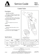
Fig. 1: VEGACAP 27 with plastic housing
1 Housing lid
2 Housing with electronics
3 Processtting
4 active screen segment
5 active probe
Thetypelabelcontainsthemostimportantdataforidenticationand
use of the instrument:
•
Article number
•
Serial number
•
Technical data
•
Article numbers, documentation
With the serial number, you can access the delivery data of the instru-
mentvia"www.vega.com","VEGA Tools"and"Instrument search".
Youcanndtheserialnumberontheinsideoftheinstrumentaswell
as on the type label on the outside.
Scope of delivery
Constituent parts
Type label

8
3 Product description
VEGACAP 27 • Relay (DPDT)
33758-EN-170503
3.2 Principle of operation
VEGACAP 27 is an adjustment-free, capacitive point level sensor for
liquids.
Typicalapplicationsareoverllordryrunprotectionsforadhesiveas
well as conductive liquids.
The probe works in liquids from a dielectric constant of 1.5.
Probe, measured product and vessel wall form an electrical capacitor.
Thecapacitanceisinuencedbythreemainfactors.
1
2
3
Fig. 2: Functional principle - Plate capacitor
1 Distance between the electrode surfaces
2 Size of the electrode surfaces
3 Type of dielectric between the electrodes
The probe and the vessel wall are the capacitor plates. The measured
product is the dielectric. Due to the higher dielectric constant of the
product compared to air, the capacitance increases as the probe is
gradually covered.
The capacitance change is converted by the electronics module into
a switching command.
VEGACAP 27 is a compact instrument, i.e. it can be operated without
external evaluation system. The integrated electronics evaluates the
level signal and outputs a switching signal. With this switching signal,
a connected device can be operated directly (e.g. a warning system,
a pump etc.).
Thedataforpowersupplyarespeciedinchapter"Technical data".
3.3 Adjustment
The probe can be adapted to the dielectric constant of the product
directly on the electronics module.
A switching command can be triggered when the probe is covered or
laid bare.
Ontheelectronicsmoduleyouwillndthefollowingdisplayand
adjustment elements:
•
Control lamp for indication of the switching status
•
Potentiometer for switching point adaptation (covered)
Application area
Functional principle
Voltage supply

9
3 Product description
VEGACAP 27 • Relay (DPDT)
33758-EN-170503
•
DIL switch for mode adjustment
3.4 Packaging, transport and storage
Your instrument was protected by packaging during transport. Its
capacity to handle normal loads during transport is assured by a test
based on ISO 4180.
The packaging of standard instruments consists of environment-
friendly, recyclable cardboard. For special versions, PE foam or PE
foil is also used. Dispose of the packaging material via specialised
recycling companies.
Transport must be carried out in due consideration of the notes on the
transport packaging. Nonobservance of these instructions can cause
damage to the device.
The delivery must be checked for completeness and possible transit
damage immediately at receipt. Ascertained transit damage or con-
cealed defects must be appropriately dealt with.
Up to the time of installation, the packages must be left closed and
stored according to the orientation and storage markings on the
outside.
Unless otherwise indicated, the packages must be stored only under
the following conditions:
•
Not in the open
•
Dry and dust free
•
Not exposed to corrosive media
•
Protected against solar radiation
•
Avoiding mechanical shock and vibration
•
Storageandtransporttemperatureseechapter"Supplement -
Technical data - Ambient conditions"
•
Relative humidity 20 … 85 %
With an instrument weight of more than 18 kg (39.68 lbs) suitable and
approved equipment must be used for lifting and carrying.
Packaging
Transpor
t
Transport inspection
Storage
Storage and transport
temperature
Lifting and carrying

10
4 Mounting
VEGACAP 27 • Relay (DPDT)
33758-EN-170503
4 Mounting
4.1 General instructions
Make sure that all parts of the instrument coming in direct contact
with the process, especially the sensor element, process seal and
processtting,aresuitablefortheexistingprocessconditions,such
as process pressure, process temperature as well as the chemical
properties of the medium.
Youcanndthespecicationsinchapter"Technical data"andonthe
nameplate.
The instrument is suitable for standard and extended ambient condi-
tions acc. to DIN/EN/IEC/ANSI/ISA/UL/CSA 61010-1.
In general the level switch can be mounted in any position. The instru-
ment must be mounted in such a way that the probe is at the height of
the requested switching point.
Before beginning the welding work, remove the electronics module
from the sensor. By doing this, you avoid damage to the electronics
through inductive coupling.
Ground the probe before welding directly on the rod or cable.
With threaded versions, the housing must not be used to screw in the
instrument! Applying tightening forces on the housing can damage its
internal parts.
Use the hexagon for screwing in.
Usetherecommendedcables(seechapter"Connecting to power
supply")andtightenthecablegland.
You can give your instrument additional protection against moisture
penetration by leading the connection cable downward in front of the
cableentry.Rainandcondensationwatercanthusdraino.Thisap-
plies mainly to outdoor mounting as well as installation in areas where
high humidity is expected (e.g. through cleaning processes) or on
cooled or heated vessels.
Fig. 3: Measures against moisture ingress
Suitability for the process
conditions
Suitability for the ambient
conditions
Switching point
Welding work
Handling
Moisture

11
4 Mounting
VEGACAP 27 • Relay (DPDT)
33758-EN-170503
DonotholdVEGACAP27ontheprobe.Especiallywithheavyange
versions or long rod versions, the sensor can be damaged simply by
the weight of the instrument.
Theprocessttingmustbesealedifthereisgaugeorlowpressurein
the vessel. Before use, check if the seal material is resistant against
the measured product and the process temperature.
Themax.permissiblepressureisspeciedinchapter"Technical
data"oronthetypelabelofthesensor.
Metric threads
In the case of instrument housings with metric thread, the cable
glands are screwed in at the factory. They are sealed with plastic
plugs as transport protection.
You have to remove these plugs before electrical connection.
NPT thread
In the case of instrument housings with self-sealing NPT threads, it is
not possible to have the cable entries screwed in at the factory. The
free openings for the cable glands are therefore covered with red dust
protection caps as transport protection.
Prior to setup you have to replace these protective caps with ap-
proved cable glands or close the openings with suitable blind plugs.
4.2 Mounting instructions
Duetotheeectsofagitators,equipmentvibrationorsimilar,thelevel
switch can be subjected to strong lateral forces. For this reason, do
not use an overly long electrode for VEGACAP 27, but check if you
canmountashortlevelswitchonthesideofthevesselinhorizontal
position.
Extreme vibration caused by the system, e.g. due to agitators or
turbulenceinthevesselfromuidisation,cancausetheprobeof
VEGACAP 27 to vibrate in resonance. If a longer rod version is neces-
sary, you can secure the probe by fastening a suitable brace or guy
directly above the end of the rod.
Iftheinstrumentismountedinthellingstream,unwantedfalse
measurement signals can be generated. For this reason, mount the
instrument at a position in the vessel where no disturbances, e.g. from
llingopenings,agitators,etc.,canoccur.
This applies particularly to instrument versions with a longer probe.
Transport
Pressure/V
acuum
Cable entries - NPT
thread
Cable glands
Agitatorsanduidization
Inowingmedium

12
4 Mounting
VEGACAP 27 • Relay (DPDT)
33758-EN-170503
Fig.4:Inowingmedium

13
5 Connecting to power supply
VEGACAP 27 • Relay (DPDT)
33758-EN-170503
5 Connecting to power supply
5.1 Preparing the connection
Always keep in mind the following safety instructions:
Warning:
Connect only in the complete absence of line voltage.
•
The electrical connection must only be carried out by trained
personnel authorised by the plant operator.
•
Alwaysswitchopowersupply,beforeconnectingordisconnect-
ing the instrument.
Connect the voltage supply according to the following connection
diagrams. The electronics module CAP E31R is designed in protec-
tion class I. To maintain this protection class, it is absolutely neces-
sary that the ground conductor be connected to the internal ground
terminal. Take note of the general installation regulations.
Thedataforpowersupplyarespeciedinchapter"Technical data".
The instrument is connected with standard three-wire cable without
screen. If electromagnetic interference is expected which is above the
test values of EN 61326 for industrial areas, screened cable should
be used.
Make sure that the cable used has the required temperature resist-
anceandresafetyformax.occurringambienttemperature
Use cable with round cross-section. A cable outer diameter of
5…9mm(0.2…0.35in)ensuresthesealeectofthecablegland.
Ifyouareusingcablewithadierentdiameterorcross-section,
exchange the seal or use a suitable cable gland.
Note:
When placing the housing cover, make sure that the inspection glass
is above the signal lamp of the electronics module.
5.2 Wiring plan, single chamber housing
We recommend connecting VEGACAP 27 in such a way that the
switching circuit is open when there is a level signal, line break or
failure (safe state).
The relays are always shown in non-operative condition.
The two relays (DPDT) work synchronously. Hence it is possible to
control also e.g. a horn and a magnet valve.
Note safety instructions
Voltage supply
Connection cable
Wiring plan

14
5 Connecting to power supply
VEGACAP 27 • Relay (DPDT)
33758-EN-170503
234 567
+
L1
–
N
81
1
2
3
Fig. 5: Wiring plan
1 Relay output
2 Relay output
3 Voltage supply

15
6 Setup
VEGACAP 27 • Relay (DPDT)
33758-EN-170503
6 Setup
6.1 General information
Theguresinbracketsrefertothefollowingillustrations.
Ontheelectronicsmoduleyouwillndthefollowingdisplayand
adjustment elements:
•
Potentiometer for switching point adaptation
•
DIL switch for mode adjustment - A/B
•
Control lamp
Note:
As a rule, always set the mode with the mode switch (5) before start-
ing setup VEGACAP 27. The switching output will change if you set
the mode switch (5) afterwards. This could possibly trigger other con-
nected instruments or devices.
6.2 Adjustment elements
3
4
5
6
1
2
Fig. 6: Oscillator with relay output
1 Type label
2 Connection terminals
3 Tensile proving ring
4 Control lamp
5 DIL switch for mode adjustment
6 Potentiometer for switching point adaptation
The switching status of the electronics can be checked with closed
housing(onlyplastichousing),see"Function table".
Note:
When placing the housing cover, make sure that the inspection glass
is above the signal lamp (LED) of the electronics module.
Function/Conguration

16
6 Setup
VEGACAP 27 • Relay (DPDT)
33758-EN-170503
ToadjustVEGACAP27,loosenrstofallthefourscrewsontheup-
per side of the instrument with a screwdriver and remove the housing
cover.
You can adapt the switching point to the solid with the potentiometer.
The electronics is adjustment free and an adaption is only necessry in
exceptions.See"Exceptions".
With the mode switch you can change the switching condition of the
relay.Youcansettherequiredmode(A-max.detectionoroverll
protection, B - min. detection or dry run protection).
We recommend connecting according to the idle current principle
(relaycontactdeenergizeswhentheswitchingpointisreached),
because the relay always takes on the same (safe) state if a failure is
detected or in case of mains failure.
Control lamp for indication of the switching status
•
Control lamp on = Relay deenergised
The measuring system is immediately ready for operation.
The switching point must no longer be set with VEGACAP 27.
The probe has an active tip and a screen segment. Thanks to the
screen segment, the so called standing capacitance, caused by the
vessel after installation of the probe, is mainly compensated.
As a default setting, the electronics module is adjusted to the basic
capacitance of the probe. The relay output switching when the active
tip is covered (active tip: 50 … 150 mm / 2 … 5.9 in) of the electrode.
Changing dielectric values of the products, such as e.g. caused in
mixing vessels are no problem for the switching accuracy within the
active pin. The selection of the electrode length is hence very impor-
tant because the length of the electrode determines the switching
point. This switching point cannot be shifted on the electrode.
In exceptions, e.g. in pipelines or if the probe is mounted very close to
thevesselwall,itcanhappenaththeprobesignalsalreadyoverlling
(covering) in uncovered condition.
In this case, the switching point must be re-adjusted.
Foradjustment,thevesselmustnotbelledandtheswitchingpoint
adjustment is also possible in dismounted condition.
A fresh adjustment is necessary in the following cases:
•
for probes with a length of more than 3 m (9.8 ft)
•
in narrow space installation conditions with high standing capaci-
tance (e.g. in tubes etc.)
•
after exchange of the electronics module
Proceed as follows for a fresh adjustment:
1. Make sure that the probe is uncovered.
2. Pierce the cover of the potentiometer (6) with a screwdriver.
Switching point adapta-
tion (6)
Mode adjustment (5)
Signal lamp (4)
Switching point adjust-
ment
Exceptions
Fresh adjustment

17
6 Setup
VEGACAP 27 • Relay (DPDT)
33758-EN-170503
3. Turnthebelowpotentiometer(6)rstofallanticlockwise(max.20
turns)untilthecontrollampsignals"covered".
ModeA(overllprotection)=controllamplights
Mode B (dry run protection) = control lamp extinguishes
If this condition is already reached, you can continue with the next
step.
4. Turn the potentiometer (6) very slowly (due to the damping) clock-
wiseuntilthecontrollampsignals"uncovered".
ModeA(overllprotection)=controllampextinguishes
Mode B (dry run protection) = control lamp lights
5. Turn the potentiometer (6) clockwise according to the following
table.
6. The probe is now ready for operation.
Sensitivity
Standard very sensitive
additional turns Dielectric constant >2
= 2 turns
Dielectric constant >1.5
= 1 turn
Tab. 1: Number of additional turns for the potentiometer (6)
Note:
With the measurement of products with very low dielectric values, the
number of turns can be reduced up to 1 according to the table.
This setting is too sensitive with conductive, adhesive products.
Note:
When placing the housing cover, make sure that the inspection glass
is above the signal lamp of the electronics module.
6.3 Function table
The following table provides an overview of the switching conditions
depending on the set mode and the level.
Level Switching status Control lamp
Mode A
Overowprotec-
tion
53 4
(8)(6) (7)
Relayenergized
Mode A
Overowprotec-
tion
53 4
(8)(6) (7)
Relay deener-
gized

18
6 Setup
VEGACAP 27 • Relay (DPDT)
33758-EN-170503
Level Switching status Control lamp
Mode B
Dry run protection
53 4
(8)(6) (7)
Relayenergized
Mode B
Dry run protection
53 4
(8)(6) (7)
Relay deener-
gized
Failure of the sup-
ply voltage
(mode A/B)
any
53 4
(8)(6) (7)
Relay deener-
gized

19
7Maintenanceandfaultrectication
VEGACAP 27 • Relay (DPDT)
33758-EN-170503
7 Maintenanceandfaultrectication
7.1 Maintenance
If the device is used properly, no special maintenance is required in
normal operation.
7.2 Rectify faults
The operator of the system is responsible for taking suitable meas-
ures to rectify faults.
VEGACAP27oersmaximumreliability.Nevertheless,faultscanoc-
cur during operation. These may be caused by the following, e.g.:
•
Sensor
•
Process
•
Voltage supply
•
Signal processing
Therstmeasuretotakeistochecktheoutputsignal.Inmanycases,
thecausescanbedeterminedthiswayandthefaultsquicklyrectied.
Should these measures not be successful, please call in urgent cases
the VEGA service hotline under the phone no. +49 1805 858550.
Thehotlineismanned7daysaweekround-the-clock.Sinceweoer
this service worldwide, the support is only available in the English
language. The service is free, only standard call charges are incurred.
Error Reason Rectication
•
The instrument signals
covered without covering
with the medium
•
The instrument signals
covered with covering
with the medium
Wrong mode selected Setthecorrectmodeonthemodeswitch(A-overow
protection, B - dry run protection). Wiring should be car-
ried out according to the idle current principle.
Operating voltage too low Check operating voltage
Shortcircuit in the probe,
e.g. because of moisture in
the housing
Remove the electronics module. Check the resistance
between the marked plug connections. See the follow-
ing instructions.
Electronics defective Press the mode switch (A/B). If the instrument then
changes the mode, the instrument may be mechani-
cally damaged. Should the switching function in the
correct mode still be faulty, return the probe for repair.
Push the mode switch. If the probe then does not
change the mode, the electronics module may be de-
fective. Exchange the electronics module.
Remove the electronics module. Check the resistance between the
two plug connections.
There must no longer be a connection (high impedance). If there is
still a connection - exchange the instrument or return it for repair
Reaction when malfunc-
tion occurs
Causes of malfunction
Faultrectication
24 hour service hotline
Checking the switching
signal
Check the resistance in
the probe

20
7Maintenanceandfaultrectication
VEGACAP 27 • Relay (DPDT)
33758-EN-170503
6
7
4
3
C
PH
C
M
2 M
Ω
2 M
Ω
2 M
Ω
3
2
1
Fig. 21: Check the resistance in the probe
1 Contact 1 (middle pin)
2 Variable capacitor (phase)
3 Capacitor
Measure the resistance values between the following contacts with an
ohmmeter(rangeMΩ).
Contact 4 against contact 1 (middle pin)
Theresistormustbe2MΩ.
If the resistor is lower, this means moisture in the housing or a fault in
the electrode insulation. A possible reason could be also a non-insu-
lated electrode which is used in a conductive (humid) medium.
If the resistor is higher or if the connection is interrupted, the reason is
mostly a contact error in the adapter plate or a defective resistor due
to strong electrostatic arking.
In both cases, the probe must be repaired in our premises.
Contact 4 against vessel
The electrical connection between contact 4 and metal vessel (not
themountingbossorprobeange)shouldgood.Measuretheresist-
ance value between contact 4 and vessel with an ohmmeter (range
very small).
•
Shortcircuit(0…3Ω)-optimumconnection
•
Resistor>3Ω-badconnection
/