
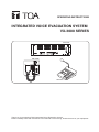
OPERATING INSTRUCTIONS
INTEGRATED VOICE EVACUATION SYSTEM
VX-3000 SERIES
RM-200SF
VX-3004F
RM-300X
Thank you for purchasing TOA's Integrated Voice Evacuation System.
Please carefully follow the instructions in this manual to ensure long, trouble-free use of your equipment.

2
TABLE OF CONTENTS
Chapter 1 : NOMENCLATURE
1. VX-3004F, VX-3008F, AND VX-3016F
VOICE EVACUATION FRAME ............................................................... 1-2
2. RM-200SF FIREMAN’S MICROPHONE AND
RM-320F REMOTE MICROPHONE EXTENSION ..................... 1-5
2.1. RM-200SF .......................................................................................................... 1-5
2.2. RM-320F ............................................................................................................ 1-7
3. RM-300X REMOTE MICROPHONE AND
RM-210F REMOTE MICROPHONE EXTENSION
..................... 1-8
3.1. RM-300X ............................................................................................................ 1-8
3.2. RM-210F ............................................................................................................ 1-9
Chapter 2 : INDICATOR STATUS OF REMOTE MICROPHONES
1. RM-200SF FIREMAN’S MICROPHONE AND
RM-320F REMOTE MICROPHONE EXTENSION
................... 2-2
1.1. Indicator State at the Time of Zone Selection .................................................... 2-2
1.2. Talk Key Indicators ............................................................................................ 2-3
1.3. Indicator State at the Time of Base Pattern Change ........................................ 2-4
1.4. Indicator State at the Time of General-Purpose Broadcast Pattern ................. 2-4
1.5. Indicator State at the Time of General/BGM Broadcast ................................... 2-5
1.6. Indicator State at the Time of RM Broadcast Status Display ............................ 2-5
1.7. Indicator State at the Time of Lamp Test ........................................................... 2-6
1.8. Indicator State at the Time of Failure Output Receipt ........................................ 2-7
1.9. Indicator State at the Time of Failure Output Reset .......................................... 2-8
1.10. Indicator State at the Time of Emergency Broadcast Pattern Start ................ 2-9
1.11. Indicator State at the Time of Emergency Broadcast Pattern Stop ................ 2-10
1.12. Indicator State at the Time of Emergency Broadcast Pattern Start/Stop ....... 2-11
1.13. Indicator State at the Time of Emergency Sequence Stop ............................ 2-12
1.14. Indicator State at the Time of Emergency Sequence Phase Shift ................. 2-13
1.15. Indicator State at the Time of Emergency Reset ............................................ 2-14
1.16. Indicator State at the Time of Emergency Broadcast Silence ........................ 2-15
1.17. Indicator State at the Time of Emergency EV Broadcast ............................... 2-16
1.18. Indicator State at the Time of Emergency Acknowledge ................................ 2-17
1.19. Indicator State at the Time of Disablement of EMG Control from CIN ........... 2-19
1.20. Indicator State at the Time of Audio Monitor .................................................. 2-20
1.21. Indicator State at the Time of Intended Control Input .................................... 2-20
1.22. Indicator State at the Time of Intended Control Output (Pulse) ..................... 2-21
1.23. Indicator State at the Time of Intended Control Output (Level) ..................... 2-21
1.24. Indicator State at the Time of Zone Volume Adjustment (Pulse) ................... 2-22
1.25. Indicator State at the Time of Input Volume Adjustment (Pulse) ................... 2-23
1.26. Indicator State at the Time of Emergency Warning Broadcast ...................... 2-24

3
2. RM-300X REMOTE MICROPHONE AND
RM-210F REMOTE MICROPHONE EXTENSION
................... 2-25
2.1. Indicator State at the Time of Zone Selection .................................................. 2-25
2.2. Talk Key Indicators ........................................................................................... 2-26
2.3. Indicator State at the Time of Base Pattern Change ....................................... 2-26
2.4. Indicator State at the Time of General-Purpose Broadcast Pattern ................ 2-27
2.5. Indicator State at the Time of General/BGM Broadcast .................................. 2-27
2.6. Indicator State at the Time of RM Broadcast Status Display ........................... 2-28
2.7. Indicator State at the Time of Lamp Test ......................................................... 2-28
2.8. Indicator State at the Time of Failure Output Receipt ...................................... 2-29
2.9. Indicator State at the Time of Failure Output Reset ........................................ 2-30
2.10. Indicator State at the Time of Emergency Broadcast Pattern Start ............... 2-31
2.11. Indicator State at the Time of Emergency Broadcast Pattern Stop ............... 2-32
2.12. Indicator State at the Time of Emergency Broadcast Pattern Start/Stop ...... 2-33
2.13. Indicator State at the Time of Emergency Sequence Stop ........................... 2-34
2.14. Indicator State at the Time of Emergency Sequence Phase Shift ................ 2-35
2.15. Indicator State at the Time of Emergency Reset ........................................... 2-36
2.16. Indicator State at the Time of Emergency Broadcast Silence ........................ 2-37
2.17. Indicator State at the Time of Emergency EV Broadcast .............................. 2-38
2.18. Indicator State at the Time of Emergency Acknowledge .............................. 2-39
2.19. Indicator State at the Time of Disablement of EMG Control from CIN ........... 2-41
2.20. Indicator State at the Time of Audio Monitor ................................................ 2-42
2.21. Indicator State at the Time of Intended Control Input ................................... 2-42
2.22. Indicator State at the Time of Intended Control Output (Pulse) .................... 2-43
2.23. Indicator State at the Time of Intended Control Output (Level) .................... 2-43
2.24. Indicator State at the Time of Zone Volume Adjustment (Pulse) .................. 2-44
2.25. Indicator State at the Time of Input Volume Adjustment (Pulse) .................. 2-45
2.26. Indicator State at the Time of Emergency Warning Broadcast ..................... 2-46
Chapter 3 : OPERATION
1. BGM AND GENERAL BROADCAST ................................................ 3-2
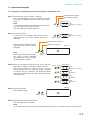
1.1. Broadcasting from the RM-200SF, RM-300X, RM-320F, and RM-210F ........... 3-2
1.2. Assignment Example ........................................................................................ 3-2
1.3. Operation Examples ......................................................................................... 3-3
2. EMERGENCY WARNING BROADCAST ....................................... 3-9
3. EMERGENCY BROADCAST ................................................................ 3-10
3.1. Typical System Examples ................................................................................ 3-10
3.2. Remote Microphone Operation Example ........................................................ 3-12
4. MAKING ALL-ZONE EMERGENCY BROADCAST ................ 3-18
4.1. Priority Control of the All-Zone Emergency Broadcast ..................................... 3-18
4.2. Making All-zone Emergency Broadcast from the RM-300X ............................ 3-19
4.3. Making All-zone Emergency Broadcast from the RM-200SF ......................... 3-20
5. DETECTING FAULT ................................................................................... 3-21
5.1. Fault Detection Setting Example ...................................................................... 3-21
5.2. Case Example of Malfunction ......................................................................... 3-22
5.3. Remote Microphone's Operation Example ..................................................... 3-23
5.4. VX-3004F's Operation Example ...................................................................... 3-24

4
5.5. Example of Executing the Failure Reception and Failure Reset
by Way of the Control Input Terminals ............................................................ 3-25
6. LAMP TEST .................................................................................................... 3-26
6.1. Remote Microphone's Operation Example ...................................................... 3-26
6.2. VX-3004F's Operation Example ..................................................................... 3-27
7. OTHER FUNCTIONS ................................................................................. 3-28
7.1. Audio Monitor ................................................................................................... 3-28
7.2. Intended Control Input Operation .................................................................... 3-29
7.3. Intended Control Output Operation (Pulse) ..................................................... 3-29
7.4. Intended Control Output Operation (Level) ..................................................... 3-30

Chapter 1
NOMENCLATURE

1-2
Chapter 1
NOMENCLATURE
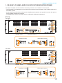
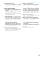
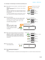
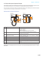
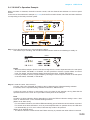
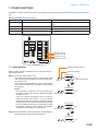
1. VX-3004F, VX-3008F, AND VX-3016F VOICE EVACUATION FRAME
VX-3004F, VX-3008F, and VX-3016F are collectively referred to as “VX-3000F” in this manual.
• The VX-3000F is a unit designed to control the Voice evacuation announcements of the VX-3000 series voice
evacuation system.
• Ithasaudioinputterminalsandcanoutputtheampliedaudiosignalstothespeakerlineswhentheoptional
powerampliermodulesaremounted.
• Compatiblewithnetwork,thesystemcanbeconguredindistributedarrangement.
[Front]
Amplifier section Fault status section
[Amplifier section] [Fault status section]
9
10
11
12
13
14
15
16
17
18
19
20
21
22 23
1
2
3
5
6
7
8
4
VX-3004F
VX-3008F
Amplifier section Fault status section
1
2
3
5
6
7
8
[Amplifier section] [Fault status section]
9
10
11
12
13
14
15
16
17
18
19
20
21
22 23
4

1-3
Chapter 1
NOMENCLATURE
1. Power indicator (Green)
Lights when the power is supplied.
Flashes in standby state.
2. RUN indicator (Green)
Normallyashescontinuously.Goesoffwhilein
a CPU off state (p. 3-18). Also goes off while in
standby state*
1
.
*
1
A state during power failures or a state that the
unit is internally initialized after power-on
3. Emergency indicator (Red)
Lights when the VX-3000 system is in an
emergency condition or while in a CPU off state
(p. 3-18).
4. CPU off indicator (Red)
Lights while in a CPU off state (p. 3-18).
5. LAN A indicator (Green)
Lights when the LAN link A connector on the
rearpanelisconnected,andashesduringLAN
communications.
6. LAN B indicator (Green)
Lights when the LAN link B connector on the
rearpanelisconnected,andashesduringLAN
communications.
7. RS link A indicator (Green)
Lights when the RS link A connector on the
rear panel is connected, and ashes while
communications are being performed via the RS
link A connector.
8. RS link B indicator (Green)
Lights when the RS link B connector on the
rear panel is connected, and ashes while
communications are being performed via the RS
link B connector.
9. Amplier peak indicators (Red)
Showtheinputsignalstatetothepoweramplier
whenthepowerampliermoduleisinstalled.
The indicator corresponding to the module slot
port will light if the input signal level exceeds +0.5
dB*
2
.
Itremainsunlitwhennopowerampliermodule
is installed.
10. Amplier signal indicators (Green)
Showtheinputsignalstatetothepoweramplier
whenthepowerampliermoduleisinstalled.
The indicator corresponding to the module slot
port will light if the input signal level exceeds
-
25
dB*
2
.
Itremainsunlitwhennopowerampliermodule
is installed.
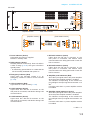
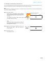
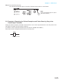
VX-3016F
[Amplifier section] [Fault status section]
9
10
11
12
13
14
15
16
17
18
19
20
21
22
23
1
2
3
5
6
7
8
4
Amplifier section Fault status section
*
2
0 dB = 1 V

1-4
Chapter 1
NOMENCLATURE
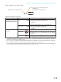
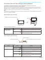
11. Amplier operate indicators (Green)
The indicator corresponding to the module slot
port will light or go off depending on the operation
state of the power amplier when the power
ampliermoduleisinstalled.
Operating status Indicator status
In-use Lit
Standby Unlit
DC fuse blowout Unlit
Protection* activated Unlit
* The built-in protection circuit operates if some
irregularitiesoccurinsidetheamplier suchas
abnormal temperature rise or fan failure.
Itremainsunlit whennopowerampliermodule
is installed.
12. Amplier power indicators (Green)
The indicator corresponding to the module slot
port will light or go off depending on the operation
state of the power amplier when the power
ampliermoduleisinstalled.
Operating status Indicator status
In-use Lit
Standby Lit
DC fuse blowout Unlit
Protection* activated Lit
* The built-in protection circuit operates if some
irregularitiesoccurinsidetheamplier suchas
abnormal temperature rise or fan failure.
Itremainsunlit whennopowerampliermodule
is installed.
13. Zone fault indicators (Yellow)
Lightsorasheswhenthespeakerlinesurveillance
function detects 3 types of failures: poor insulation
(ground fault), overload (line short), and cable
disconnection.
14. Fuse fault indicator (Yellow)
Lights or ashes when DC fuse blowout are
detected.
15. Power fault indicator (Yellow)
Lights or ashes when failures are detected in
Power Supply Manager.
16. CPU fault indicator (Yellow)
Lights while in a CPU off state (p. 3-18) or when a
failure is detected in the VX-3000F.
17. General fault indicator (Yellow)
Lights while in a CPU off state (p. 3-18) Lights or
asheswhenafailureisdetectedinthesystem.
18. Unit fault indicator (Yellow)
Lightsorasheswhenafailureisdetectedinthe
unit.
19. Network fault indicator (Yellow)
Lights or ashes when failures are detected in
communications with the other VX-3000F.
It also ashes or lights at network setting and
whenacongurationerroroccurs.
20.
Emergency microphone fault indicator (Yellow)
Lights or ashes when failures are detected in
Emergency Microphone.
21. Fault ACK key
The buzzer will sound and Fault indicator will
asheswhenafailureisdetectedinthesystem.
Press this key to stop the buzzer and switches the
Faultindicatorfromashingtosteadyon.
22. Fault reset key
Pressing this key resets the failure information
(the buzzer and fault indicators) for the system.
23. Lamp test key
Used to test each indicator on the front panel of
the VX-3000F Voice Evacuation Frame.
All indicators remain lit and the buzzer sounds as
long as this key is pressed.

1-5
Chapter 1
NOMENCLATURE
2. RM-200SF FIREMAN’S MICROPHONE AND RM-320F REMOTE
MICROPHONE EXTENSION
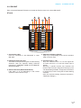
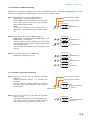
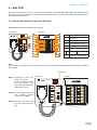
2.1. RM-200SF
• TheRM-200SFFireman’sMicrophonefeatures3functionkeys,1emergencykey,1talkkey,andtheindicator
lamps associated with these keys. Functions are assigned to the function keys using the VX-3000 Setting
Software.
• Speciallydesignedforbothemergencyandgeneralpurposebroadcastapplications,theFireman’sMicrophone
can be used for push-button zone selection and microphone broadcasts.
• VX-3000 setting software permits desired functions to be assigned to individual Function keys (equipped with
2 LED indicators).
• Up to 4 RM-320F Remote Microphone Extension units can be used with each RM-200SF Remote Microphone.
•Upto2RM-200SFFireman’sMicrophonescanbeconnectedwithinaVX-3000F.
• TheCPUswitchenablesall-zoneemergencybroadcastsfromtheRM-200SFFireman’sMicrophone,even
when the CPU malfunctions.
• Failures of Emergency buttons and signal (both control and audio) path between the microphone (including
the internal microphone element) and the VX-3000F are automatically detected.
[Front]
1. Power indicator (Green)
Lights when the power is turned on.
2. Emergency key
Assign the function concerning the emergency
broadcast to this key using the VX-3000 Setting
Software.
This key lights or ashes depending on the
assigned function.
3. Monitor speaker
Used to monitor current broadcasts.
4. Monitor speaker volume control
Adjusts the volume of the built-in Monitor speaker
(3).
5. Microphone volume control
Adjusts the input sensitivity of the Hand-held
Microphone.
6. Microphone hanger
Used to hold the unit's Hand-held Microphone.
7. CPU switch
Normally set to ON. (Factory-preset: ON)
Setting this switch to OFF in combination with the
DIP switch setting on the bottom surface allows
the all-zone emergency broadcast to be made
using a hand-held microphone by way of analog
transmission not via the CPU control.
FIREMAN'S MICROPHONE
RM-200SF
MIC SP CPU
OFF ON
1
2
3
4
5
6
7 8
9
10
11
12
13
14
15
16
17
[Hand-held microphone]
18

1-6
Chapter 1
NOMENCLATURE
8. Indication label insert slot
The label can be printed using the VX-3000
Setting Software. (See the separate Setting
Software Instructions, "PRINTING LABELS FOR
REMOTE MICROPHONES.")
9. Failure indicator (Yellow/Red)
Flashes yellow if some problem within the system
is detected.
This indicator will light yellow if the signal to the
VX-3000F to which the RM-200SF is connected
is interrupted for 5 seconds or more.
Lights red when the unit is placed in reset state by
pressing the Reset Switch (11).
10. CPU indicator (Red)
Lights red when any one of the CPU switches
on the RM-200SFs connected within the system
is set to OFF or when the all-zone emergency
broadcasts is being made by any one of the RM-
300Xs connected within the system.
11. Reset switch
Used to reactivate the RM-200SF unit.
Holding down both this switch and the R3 key
of the Function keys (14) for 2 seconds or more
causes the Failure Indicator (9) to light red,
placing the RM-200SF in reset state.
12. Status indicators (Red/Yellow/Green)
Light, ash, or go off depending on the current
operation state of function keys, failure state or
emergency state. (See the Chapter 2.)
13. Selection indicators (Green)
Light or go off depending on the current operation
state of function keys. (See the Chapter 2.)
14. Function keys (R1 – R3)
Positioned in top-down order (R1, R2, R3).
Pressing a specic function key executes the
function that has been assigned to that key by
the VX-3000 Setting Software. Assignment of
functions to specic keysis done using the VX-
3000 Setting Software. (See the separate Setting
Software Instructions, “RM Event Settings.”)
15. Microphone indicator (Green)
Lights or goes off depending on the current
operation state of the Talk key.
16. Broadcast status indicator (Yellow/Green)
Lights, ashes, or goes off depending on the
current operation state of the Talk key.
17. Talk key
Press this key to broadcast a voice announcement.
It must be pressed continuously for the duration
of the broadcast.
Thetalkkeyoperationmethodisxedto“PTT,”
and can not be changed.
18. Microphone
Used for voice announcements.

1-7
Chapter 1
NOMENCLATURE
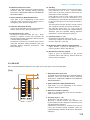
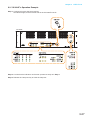
2.2. RM-320F
Each connected RM-320F Extension unit adds 20 Function keys to the base RM-200SF.
[Front]
5
1
2
3
4
5
2
3
4
1. Connection cable
Used for connection to the RM-200SF or other
RM-320F.
2. Indication label insert slot
The label can be printed using the VX-3000 Setting
Software. (See the separate Setting Software
Instructions, "PRINTING LABELS FOR REMOTE
MICROPHONES.")
3. Status indicators (Red/Yellow/Green)
Light, ash, or go off depending on the current
operation state of function keys.
4. Selection indicators (Green)
Light or go off depending on the current operation
state of function keys.
5. Function keys (1 – 20)
Keys are numbered from 1 to 10 from upper left
to bottom and from 11 to 20 from upper right to
bottom.
Pressing a specic function key executes the
function that has been assigned to that key by the
VX-3000 Setting Software. Assignment of functions
tospecickeysisdoneusingtheVX-3000Setting
Software.
(See the separate Setting Software Instructions,
"RM Event Settings.")

1-8
Chapter 1
NOMENCLATURE
3. RM-300X REMOTE MICROPHONE AND RM-210F REMOTE
MICROPHONE EXTENSION
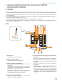
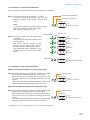
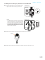
3.1. RM-300X
• The RM-300X Remote Microphone features 13 function keys, 1 covered key, 1 talk key, and the indicator
lamps associated with these. Functions are assigned to the function keys using the VX-3000 Setting Software.
• VX-3000 setting software permits desired functions to be assigned to individual Function keys (equipped with
2 LED indicators).
• Connecting RM-210F Remote Microphone Extension (maximum 7) to the RM-300X expands the number of
function keys and indicators in blocks of 10.
• Up to 8 RM-300X Remote Microphones can be connected within a VX-3000F.
• The DIP switch setting enables all-zone emergency broadcasts from the RM-300X Remote Microphone, even
when the CPU malfunctions.
[Top]
1
3 5
6
7
8
8
10
2 4 6 7 9
11 12 13
1. Microphone
Used for voice announcements.
2. Power indicator (Green)
Lights when the power is turned on.
3. Failure indicator (Yellow/Red)
Flashes yellow if some problem within the system
is detected.
This indicator will light yellow if the signal to the
VX-3000F to which the RM-300X is connected is
interrupted for 5 seconds or more.
This indicator will light red while the all-zone
emergency broadcasts is being made (p. 3-18)
or the RM-300X is in the reset process.
4. Emergency indicator (Red)
Lights or ashes depending on the function
assigned to the Emergency key.
5.
Emergency/all-zone emergency broadcast key
(Covered)
[Function concerning the emergency broadcast]
Assign the function concerning the emergency
broadcast to this key using the VX-3000 Setting
Software.
[Function concerning the all-zone emergency
broadcast]
Independently of settings made by the VX-3000
Setting Software, holding down this key for 4
seconds or more in combination with DIP switch
(14) setting causes the CPU to be bypassed,
enabling the all-zone emergency broadcast to
be made by way of analog transmissions. (See
p. 3-18.)

1-9
Chapter 1
NOMENCLATURE
6. Indication label insert slots
Labels can be printed using the VX-3000 Setting
Software. (See the separate Setting Software
Instructions, "PRINTING LABELS FOR REMOTE
MICROPHONES.")
7. Status indicators (Red/Yellow/Green)
Light, ash, or go off depending on the current
operation state of function keys, failure state or
emergency state. (See the Chapter 2.)
8. Selection indicators (Green)
Light or go off depending on the current operation
state of function keys. (See the Chapter 2.)
9. Function keys (R1 – R10)
Positioned in top-down order (R1, R2 ... R10).
Pressing a specic function key executes the
function that has been assigned to that key by the
VX-3000 Setting Software.
Assignmentoffunctionstospecickeysisdone
using the VX-3000 Setting Software. (See the
separate Setting Software Instructions, “RM
Event Settings.”)
10. Talk Key
Press this key to broadcast a voice announcement.
If the Talk key is set to “PTT “ (“press-to-talk”)
mode, then it must be pressed continuously for
the duration of the broadcast.
If the Talk key is set to “Lock” mode, then it must
be pressed once to turn the microphone on at
the beginning of a broadcast, then pressed again
to turn the microphone off once the broadcast is
nished.
The microphone can also be set to sound a chime
at the beginning and/or end of each broadcast.
The Talk key mode (“PTT” or “Lock”) and the
chime function are set using the VX-3000 Setting
Software. (See the separate Setting Software
Instructions,“UnitCongurationSetting.”)
11. Function keys (L1 – L3)
Positioned in top-down order (L1, L2, L3).
These keys operate in the same manner as the
Function keys (R1 – R10) (9).
12. Broadcast status indicator (Yellow/Green)
Lights, ashes, or goes off depending on the
current operation state of the Talk key.
13. Microphone indicator (Green)
Lights or goes off depending on the current
operation state of the Talk key. Flashes while the
chime is being activated.
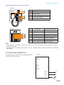
3.2. RM-210F
Each connected RM-210F Extension unit adds 10 Function keys to the base RM-300X.
[Top]
1
3
2
4
1. Indication label insert slot
The label can be printed using the VX-3000 Setting
Software. (See the separate Setting Software
Instructions, "PRINTING LABELS FOR REMOTE
MICROPHONES.")
2. Status indicators (Red/Yellow/Green)
Light, ash, or go off depending on the current
operation state of function keys.
3. Selection indicators (Green)
Light or go off depending on the current operation
state of function keys.
4. Function keys (1 – 10)
Positioned in top-down order (1, 2 ... 10).
Pressing a specic function key executes the
function that has been assigned to that key by the
VX-3000 Setting Software.
Assignment of functions to specic keys is done
using the VX-3000 Setting Software. (See the
separate Setting Software Instructions, "RM Event
Settings.")

Chapter 2
INDICATOR STATUS OF
REMOTE MICROPHONES

2-2
Chapter 2
INDICATOR STATUS OF REMOTE MICROPHONES
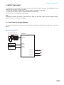
1. RM-200SF FIREMAN’S MICROPHONE AND RM-320F REMOTE
MICROPHONE EXTENSION
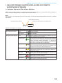
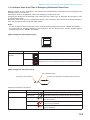
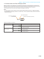
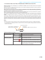
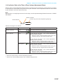
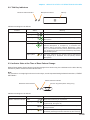
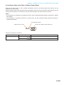
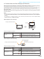
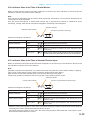
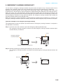
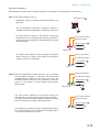
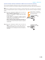
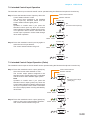
1.1. Indicator State at the Time of Zone Selection
When a zone selection (pattern or individual) function has been assigned to a function key, the 2 indicators to
the left of the key indicate its zone selection and broadcast status.
Note
For instructions on assigning functions to function keys, see the separate Setting Software Instructions, "EVENT
SETTINGS."
Broadcast Status Indicator
Zone Selection Indicator
Function key (Broadcast zone selection key)
Indicator meanings are as follows:
Indicator Status Meaning
Zone Selection Indicator Unlit
No zone selected
Lights green
Zone selected
Broadcast Status Indicator Unlit
Zones assigned to this Broadcast Zone Selection key not in
use or BGM broadcast in progress
Flashes green
A part of zones or the entire zone assigned to this Broadcast
Zone Selection key is occupied by a broadcast from another
device (secondary Remote Microphone or general EV
message), or a part of zones is engaged by a broadcast from
the primary Remote Microphone (RM-200SF).
Lights yellow
All the zones selected by this Broadcast Zone Selection
key on the primary Remote Microphone are engaged by a
broadcast from the primary Remote Microphone.
Flashes yellow
All the zones assigned to this Broadcast Zone Selection key
are engaged by a broadcast from the Secondary Emergency
Remote Microphone.
Lights red
All the zones assigned to this Broadcast Zone Selection key
are engaged by an evacuation message.
Flashes red
All the zones assigned to this Broadcast Zone Selection key
are engaged by an alert message.
Lights green
All the zones assigned to this Broadcast Zone Selection key
are engaged by a restoration message.

2-3
Chapter 2
INDICATOR STATUS OF REMOTE MICROPHONES
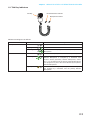
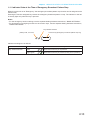
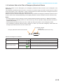
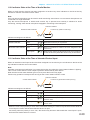
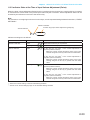
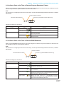
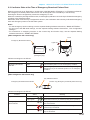
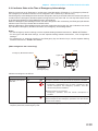
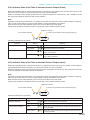
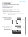
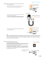
1.2. Talk Key Indicators
Broadcast Status Indicator
Microphone Indicator
Talk Key
Indicator meanings are as follows:
Indicator Status Meaning
Microphone Indicator Unlit
Microphone not in use
Lights green
Microphone in use
Flashes green
Chime broadcast in progress from the primary Remote
Microphone.
Broadcast Status Indicator Unlit
Zone not in use (microphone announcement possible)
Flashes green
A part of zones or the entire zone selected by the primary
Remote Microphone is occupied by a broadcast from
another device (secondary Remote Microphone, chime,
etc.), or a broadcast from the primary Remote Microphone
is in progress in a part of the zones selected by the primary
Remote Microphone.
Lights yellow
All zones selected by the primary Remote Microphone
are engaged by a broadcast from the primary Remote
Microphone.

2-4
Chapter 2
INDICATOR STATUS OF REMOTE MICROPHONES
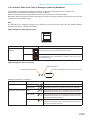
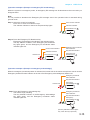
1.3. Indicator State at the Time of Base Pattern Change
When a Base pattern change function has been assigned to a function key, the 2 indicators to the left of the key
indicate its pattern selection and broadcast status.
Note
For instructions on assigning functions to function keys, see the separate Setting Software Instructions, "EVENT
SETTINGS."
Broadcast Status Indicator
Pattern Selection Indicator
Function key (Base pattern change key)
Indicator meanings are as follows:
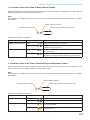
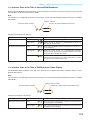
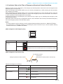
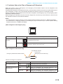
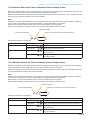
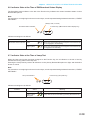
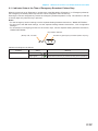
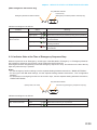
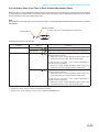
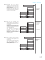
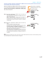
1.4. Indicator State at the Time of General-Purpose Broadcast Pattern
When a general-purpose broadcast pattern function has been assigned to a function key, the 2 indicators to the
left of the key indicate its pattern selection and broadcast status.
Note
For instructions on assigning functions to function keys, see the separate Setting Software Instructions, "EVENT
SETTINGS."
Broadcast Status Indicator
Pattern Selection Indicator
Function key (General broadcast pattern key)
Indicator meanings are as follows:
Indicator Status Meaning
Pattern Selection Indicator Unlit
When the function key is not pressed
Lights green
When the function key is pressed
(Lightsbriey,thengoesoff)
Broadcast Status Indicator Unlit
When the Base pattern assigned to the function key is not
being broadcast
Lights yellow
When the Base pattern assigned to the function key is being
broadcast (including broadcasts activated by other devices)
Indicator Status Meaning
Pattern Selection Indicator Unlit
When the function key is not pressed
Lights green
When the function key is pressed
Broadcast Status Indicator Unlit
When the broadcast pattern assigned to the function key is
not being broadcast
Flashes yellow
When the broadcast pattern assigned to the function key is
being broadcast

2-5
Chapter 2
INDICATOR STATUS OF REMOTE MICROPHONES
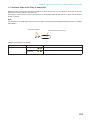
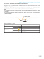
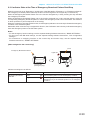
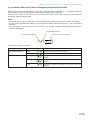
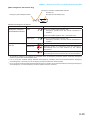
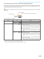
1.5. Indicator State at the Time of General/BGM Broadcast
When a general/BGM broadcast function has been assigned to a function key, the 2 indicators to the left of the
key indicate its selection and broadcast status.
Note
For instructions on assigning functions to function keys, see the separate Setting Software Instructions, "EVENT
SETTINGS."
Broadcast Status Indicator
Selection indicator
Function key (General/BGM broadcast key)
Indicator meanings are as follows:
Indicator Status Meaning
Selection Indicator Unlit
When the function key is not pressed
Lights green
When the unit is brought in general/BGM broadcast by
pressing the function key
Broadcast Status Indicator Unlit
When a general/BGM broadcast assigned to the function key
is not activated
Lights green
When the audio source for a general/BGM broadcast
assigned to the function key is being broadcast to the zones
other than those selected by this unit.
Lights yellow
When the audio source for a general/BGM broadcast
assigned to the function key is being broadcast to at least
one of the zones selected by this unit.
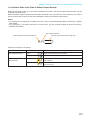
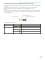
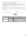
1.6. Indicator State at the Time of RM Broadcast Status Display
The Broadcast status indicator to the left of the Function key indicates the current broadcast status of other
Remote Microphone.
Note
For instructions on assigning functions to function keys, see the separate Setting Software Instructions, "EVENT
SETTINGS."
Broadcast Status Indicator
(Always unlit, not used)
Function key (RM broadcast status display key)
Indicator meanings are as follows:
Indicator Status Meaning
Broadcast Status Indicator Unlit
When the Remote Microphone assigned to the function key
is not engaged in broadcasting
Lights yellow
When the Remote Microphone assigned to the function key
is engaged in broadcasting

2-6
Chapter 2
INDICATOR STATUS OF REMOTE MICROPHONES
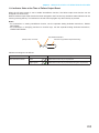
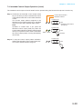
1.7. Indicator State at the Time of Lamp Test
When the lamp test function has been assigned to the Function key, the 2 indicators to the left of the key
indicate the running status of the lamp test.
Pressing the Lamp test key causes all indicators on the primary Remote Microphone to light, and the built-in
buzzer to sound.
Note
For instructions on assigning functions to function keys, see the separate Setting Software Instructions, "EVENT
SETTINGS."
Lamp Test Indicator
Function key (Lamp test key)
Indicator meanings are as follows:
Indicator Status Meaning
Lamp Test Indicator Unlit
When the function key is not pressed
Lights yellow
and green
Lamp test has been executed by pressing the function key.

2-7
Chapter 2
INDICATOR STATUS OF REMOTE MICROPHONES
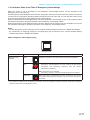
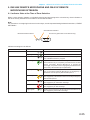
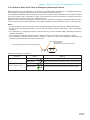
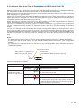
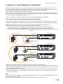
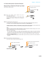
1.8. Indicator State at the Time of Failure Output Receipt
When the VX-3000 system is set to enable "Surveillance function," the failure output receipt function can be
assigned to a function key.
When the failure output receipt function has been assigned to the Function key, the 2 indicators to the left of
the key indicate the occurrence and acknowledgement status of the failure output pattern.
Notes
• For instructions on setting the surveillance function, see the separate Setting Software Instructions, "BASIC
SETTINGS."
• For instructions on assigning functions to function keys, see the separate Setting Software Instructions,
"EVENT SETTINGS."
Failure Output Receipt State Indicator
Key ON/OFF Indicator
Function key (Failure output receipt key)
Indicator meanings are as follows:
Indicator Status Meaning
Key ON/OFF Indicator Unlit
When the function key is not pressed
Lights green
When the function key is pressed (as long as it is pressed)
Failure Output Receipt
State Indicator
Flashes yellow
When the failure output pattern assigned to the function key
has occurred.
Lights yellow
Failure Output Pattern has been acknowledged after pressing
the function key.
Page is loading ...
Page is loading ...
Page is loading ...
Page is loading ...
Page is loading ...
Page is loading ...
Page is loading ...
Page is loading ...
Page is loading ...
Page is loading ...
Page is loading ...
Page is loading ...
Page is loading ...
Page is loading ...
Page is loading ...
Page is loading ...
Page is loading ...
Page is loading ...
Page is loading ...
Page is loading ...
Page is loading ...
Page is loading ...
Page is loading ...
Page is loading ...
Page is loading ...
Page is loading ...
Page is loading ...
Page is loading ...
Page is loading ...
Page is loading ...
Page is loading ...
Page is loading ...
Page is loading ...
Page is loading ...
Page is loading ...
Page is loading ...
Page is loading ...
Page is loading ...
Page is loading ...
Page is loading ...
Page is loading ...
Page is loading ...
Page is loading ...
Page is loading ...
Page is loading ...
Page is loading ...
Page is loading ...
Page is loading ...
Page is loading ...
Page is loading ...
Page is loading ...
Page is loading ...
Page is loading ...
Page is loading ...
Page is loading ...
Page is loading ...
Page is loading ...
Page is loading ...
Page is loading ...
Page is loading ...
Page is loading ...
Page is loading ...
Page is loading ...
Page is loading ...
Page is loading ...
Page is loading ...
Page is loading ...
Page is loading ...
Page is loading ...
Page is loading ...
-
 1
1
-
 2
2
-
 3
3
-
 4
4
-
 5
5
-
 6
6
-
 7
7
-
 8
8
-
 9
9
-
 10
10
-
 11
11
-
 12
12
-
 13
13
-
 14
14
-
 15
15
-
 16
16
-
 17
17
-
 18
18
-
 19
19
-
 20
20
-
 21
21
-
 22
22
-
 23
23
-
 24
24
-
 25
25
-
 26
26
-
 27
27
-
 28
28
-
 29
29
-
 30
30
-
 31
31
-
 32
32
-
 33
33
-
 34
34
-
 35
35
-
 36
36
-
 37
37
-
 38
38
-
 39
39
-
 40
40
-
 41
41
-
 42
42
-
 43
43
-
 44
44
-
 45
45
-
 46
46
-
 47
47
-
 48
48
-
 49
49
-
 50
50
-
 51
51
-
 52
52
-
 53
53
-
 54
54
-
 55
55
-
 56
56
-
 57
57
-
 58
58
-
 59
59
-
 60
60
-
 61
61
-
 62
62
-
 63
63
-
 64
64
-
 65
65
-
 66
66
-
 67
67
-
 68
68
-
 69
69
-
 70
70
-
 71
71
-
 72
72
-
 73
73
-
 74
74
-
 75
75
-
 76
76
-
 77
77
-
 78
78
-
 79
79
-
 80
80
-
 81
81
-
 82
82
-
 83
83
-
 84
84
-
 85
85
-
 86
86
-
 87
87
-
 88
88
-
 89
89
-
 90
90


TOA VX-3008F User manual
- Type
- User manual
- This manual is also suitable for
Ask a question and I''ll find the answer in the document
Finding information in a document is now easier with AI
Related papers
Other documents
-
Optimus VX-3004F User manual
-
Optimus VM-2240ER User manual
-
 Balanced Audio Technology VK-300X Owner's manual
-
 Balanced Audio Technology VK-300X Owner's manual
-
Panasonic WASA20NH Operating instructions
-
Baldwin Boxall BVRMU Operating Instructions Manual
-
Johnson Controls NEO Series User manual
-
-
ZyXEL EMG6726-B10A User guide
-
Optimus ME-200B User manual

