Page is loading ...

©2001 Kyushu Matsushita Electric Co., Ltd. All
rights reserved. Unauthorized copying and
distribution is a violation of law.
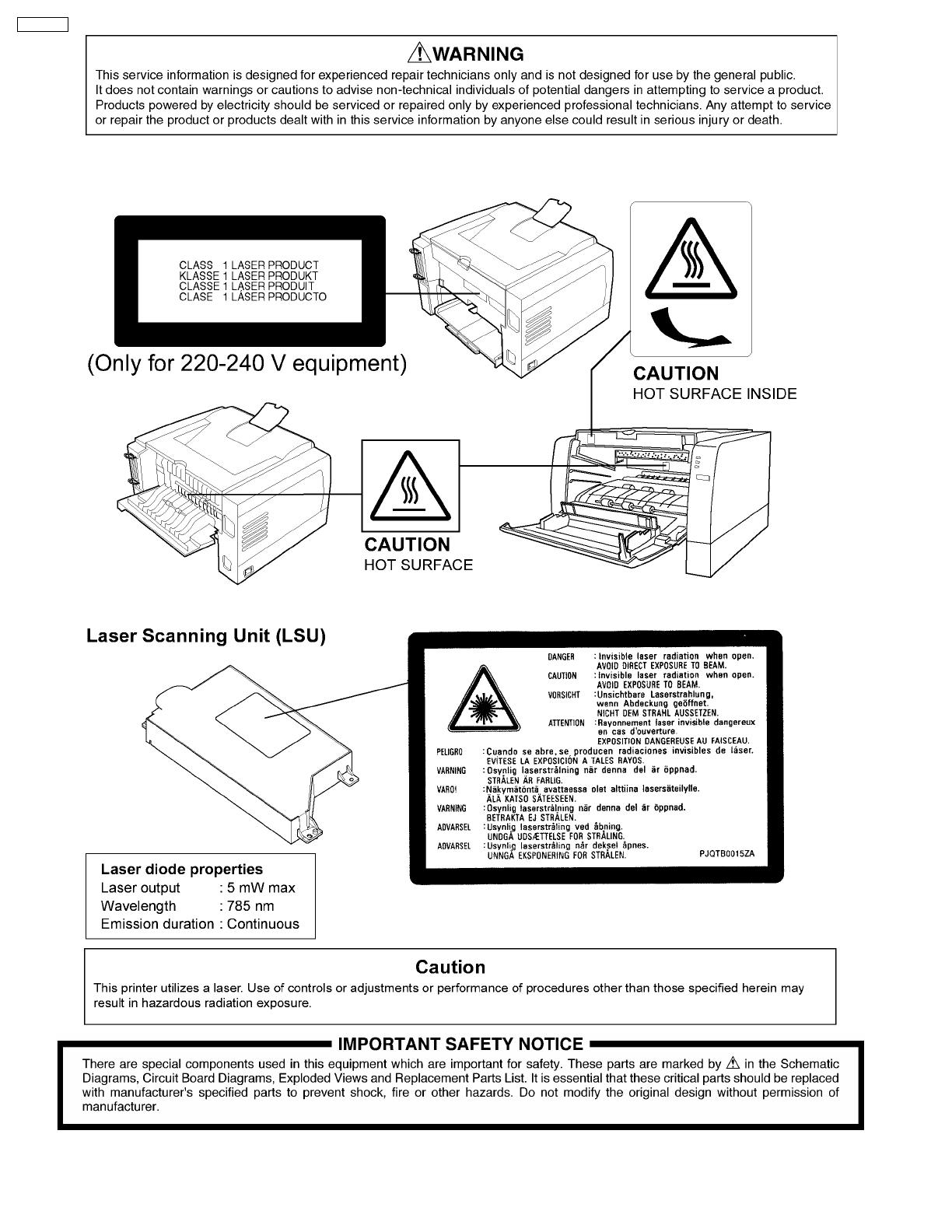
KX-P7100 Laser Printer
ORDER NO.KM60108623C0
G0
2
KX-P7100

1 Introduction 4
1.1. Specifications 4
1.2. Indicators 9
1.3. Parts Identification 11
1.4. Component Layout and Paper Path 12
1.5. Electrical Components and Sensor Boards 13
1.6. Switches and Solenoids 14
1.7. Print Process 15
1.8. Paper Feed 17
1.9. Laser Scan Unit ( Exposure ) 18
1.10. Fuser Unit 20
1.11. Paper Ejection and Paper Switchback 21
2 Installation, Setup, and Repacking 22
2.1. Installation Requirements 22
2.2. Setup 22
2.3. Repacking 24
3 Removal and Replacement Procedures 27
3.1. Front and Rear Covers 27
3.2. Right, Left and Top Covers 29
3.3. Laser Scanning Unit ( LSU ) 30
3.4. Relay Board (B) 30
3.5. High Voltage Board and Power Supply Unit 31
3.6. Indicator Board and Toner Empty Sensor Board 33
3.7. Main Controller Board and Fuser Drive Gear 33
3.8. Fan Motor 34
3.9. Gear Support Bracket, Motor and Drive Gear Unit 35
3.10. Upper Exit Roller Holder 37
3.11. Fuser Unit 38
3.12. Pickup, Paper Feed, Registration and Transfer Rollers 42
3.13. Transfer Roller Assembly 44
3.14. Auto Duplex Unit, ADU Registration Roller and ADU Pinch
Roller 45
3.15. Registration Sensor, Paper Top Detection Sensor and
Registration & Paper Top Detection Sensor Board 47
4 Electronic Circuit Description and Diagrams 49
4.1. Block Diagram 49
4.2. Connection Diagram 50
4.3. Power Supply 51
4.4. Main Control Board 52
4.5. Timing Chart 71
5 Schematic Diagram 73
5.1. Main Control Board 73
5.2. Sensors, Indicator and Relay Boards 79
6 Explanation of Connectors 81
6.1. Main Board 81
6.2. Registration & Paper Top Sensor Board 86
6.3. Paper Exit / ADU Paper Jam Sensor Board 86
6.4. Indicator Board 86
6.5. Relay Board ( B ) 86
6.6. Toner Empty Sensor Board 87
7 Component Reference Guide 88
7.1. IC1 ( Main Control CPU ) 88
7.2. IC2 ( Inverters ) 88
7.3. IC3 ( GDI ASIC ) 89
7.4. IC5 ( DRAM ) 90
7.5. IC6 ( ASIC ) 91
7.6. IC8 ( USB Chip ) 92
7.7. IC9 ( Comparators ) 92
7.8. IC10 ( Reset IC ) 92
7.9. IC11 ( Engine Control CPU ) 93
7.10. IC12 ( EEPROM ) 93
7.11. IC14 ( Motor driver IC ) 94
7.12. IC15 ( Inverters ) 94
8 Preventative Maintenance 95
8.1. General 95
8.2. Recommended Tools 95
8.3. Recommended Cleaning 95
8.4. Maintenance Tables 95
9 Troubleshooting 98
9.1. Self-Diagnostic Indicators 98
9.2. Initial Troubleshooting Flowchart 101
9.3. No Operation 102
9.4. Print Quality 103
9.5. Paper Jam 113
9.6. Call Service 118
10 Replacement Parts List with Lubrication Guide 126
10.1. Exterior 126
10.2. Right Side Parts 128
10.3. Left Side Parts ( Power Supply Unit and High Voltage
Board ) 132
10.4. Rear and Top Side Parts 133
10.5. Bottom Side Parts 136
10.6. Mechanical Base 138
10.7. Media Tray ( Paper Cassette ) 139
10.8. Packing 140
10.9. Main Control Board 141
10.10. Registration & Paper Top Detection Sensor Board 147
10.11. Paper Exit / ADU Paper Jam Sensor Board 147
10.12. Indicator Board 147
10.13. Toner Empty Sensor Board 148
10.14. Relay Board (A) 148
10.15. Relay Board (B) 148
11 Schematic Diagram for printing with A4 size 149
11.1. Main Control Board 149
11.2. Sensors, Indicator and Relay Boards 162
CONTENTS
Page Page
3
KX-P7100
1 Introduction
1.1. Specifications
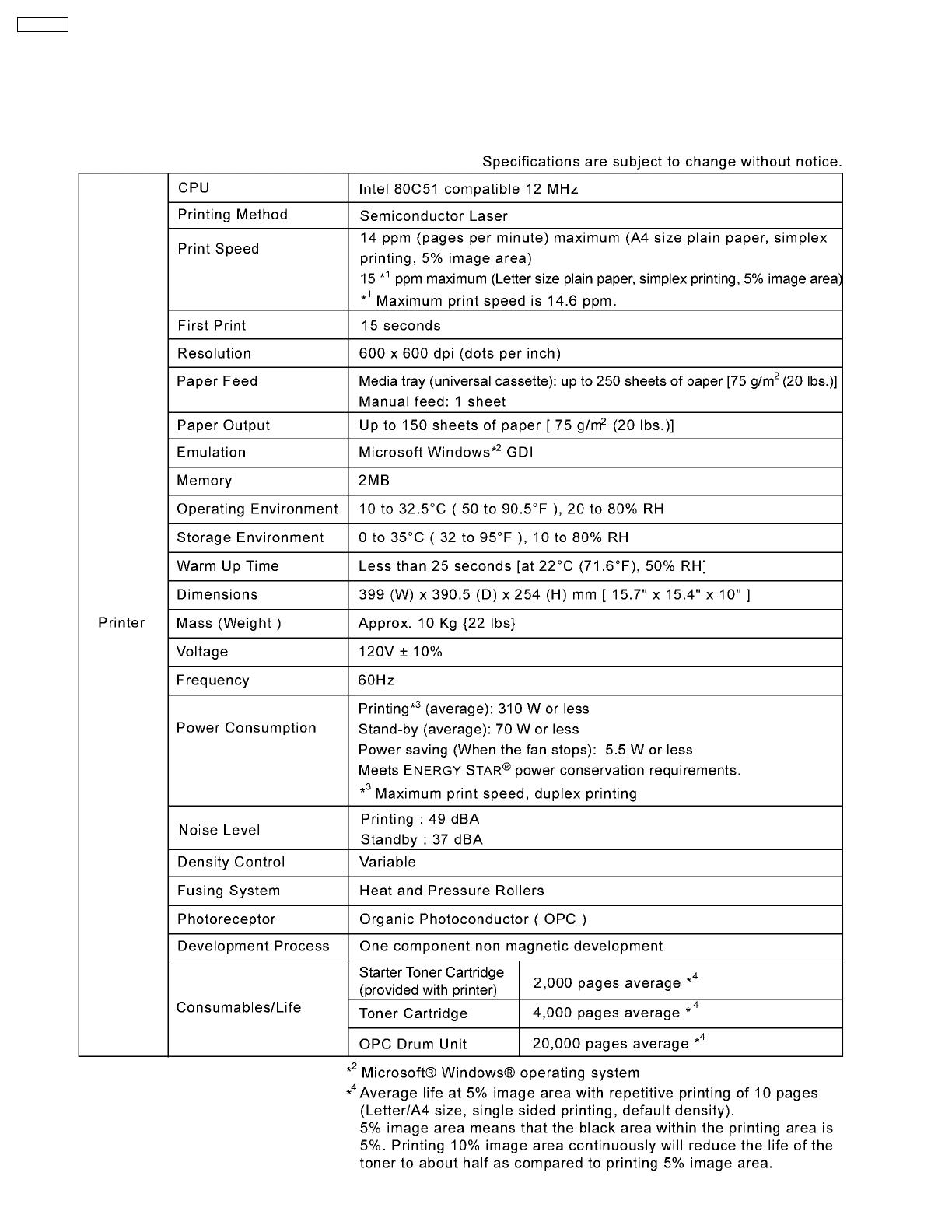
1.1.1. Printer
4
KX-P7100
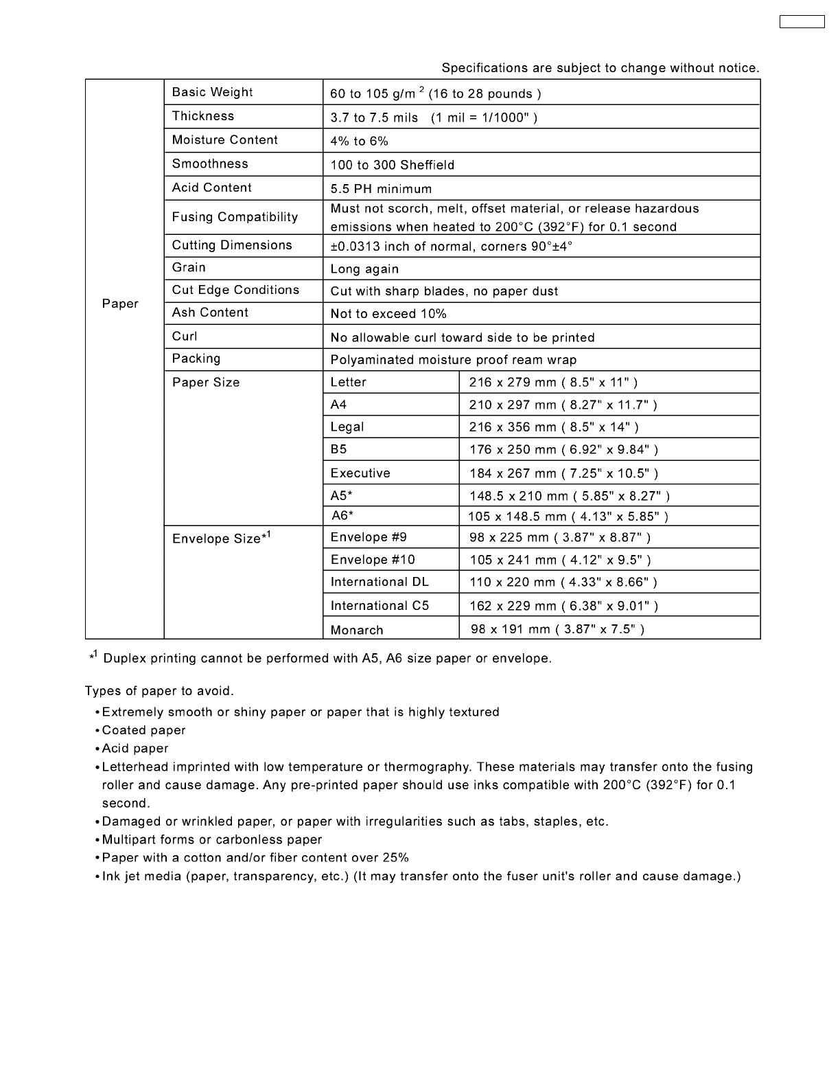
1.1.2. Paper
5
KX-P7100
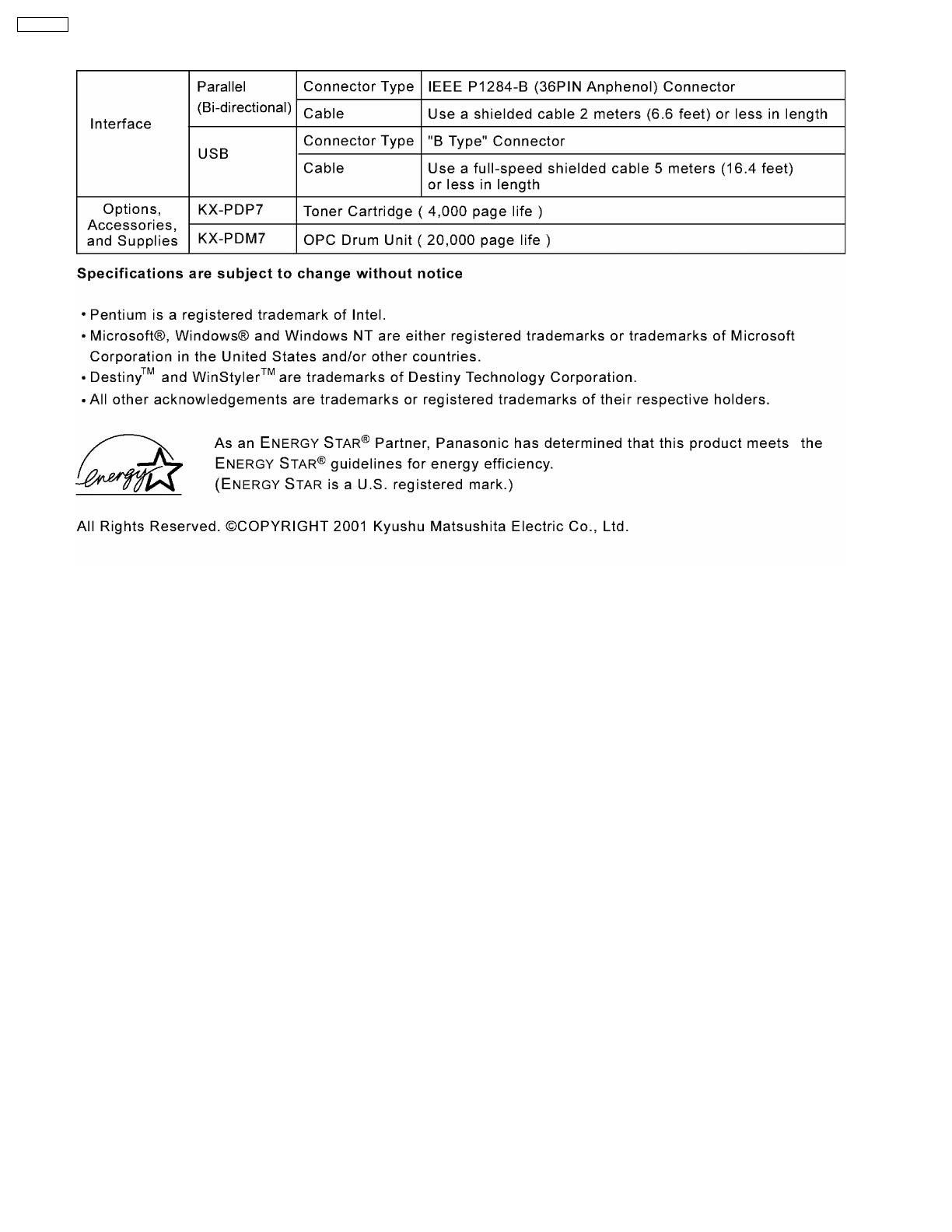
1.1.3. Interface, Options, Accessories, and Supplies
6
KX-P7100

1.1.4. Others
1.1.4.1. About Media
Available Media and Media Size
Available Paper Weights and Capacity
7
KX-P7100
Recommended Media
Transparency:
· To avoid damaging the printer, do not use ink jet transparency.
· Transparencies and adhesive material of labels should be stable at 205°C ( 400°F ), the printer’s maximum temperature.
· Re-using transparencies that have been fed through the printer once ( for example, after jams or if the transparency is ejected
without being printed ) can reduce the life of the consumables and paper path components.
· When using transparencies, if the print quality is poor, print on the other side.
Labels:
· With any label stock, the labels must completely cover the backing material.
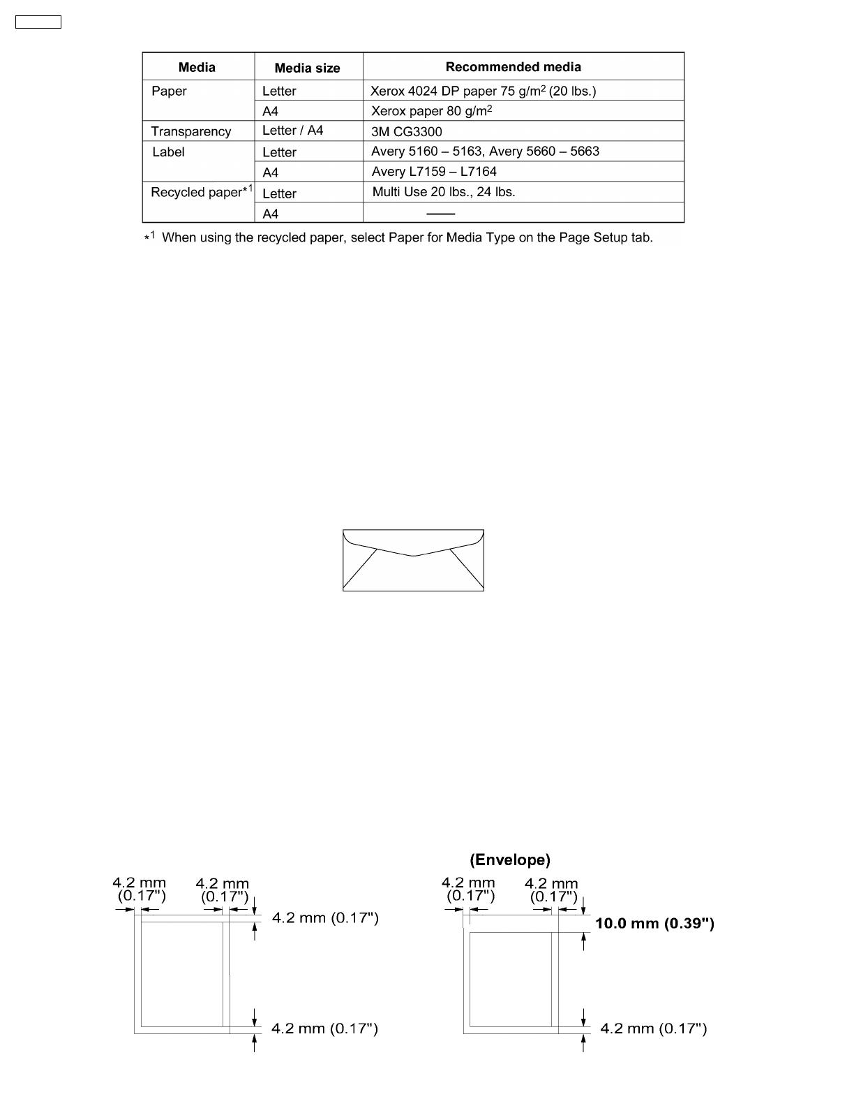
Envelope:
It is recommended that you purchase only high quality envelopes with diagonal seams, as shown in the diagram below:
High quality envelopes have the following characteristics:
· A thin, sharply creased leading edge
· Paper weight of 90 g/m2( 24 lbs. )
· Flat, free of curls, wrinkles, nicks, etc.
Note:
Wrinkles may occur, even when using high quality envelopes.
1.1.4.2. Margins and Print Area
The image ( print area ) is printed a bit smaller than the media size. 4.2 mm ( 0.17” ) is required for top, bottom and side margins.
It may be needed to adjust the page margins in the application software to match the allowable printarea.
8
KX-P7100

1.2. Indicators
1.2.1. Printer Panel
1.2.2. Indicators / Button
Three indicators show the following printer’s status.
For detailed information on the printer status and recovery, see Section 9.1.
9
KX-P7100

10
KX-P7100

1.3. Parts Identification
1.3.1. Front Side View
1.3.2. Rear Side View
11
KX-P7100
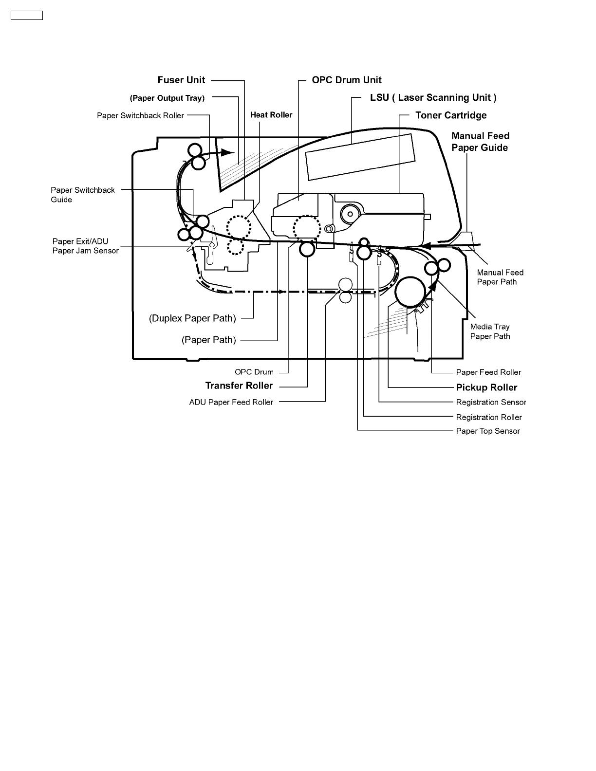
1.4. Component Layout and Paper Path
12
KX-P7100
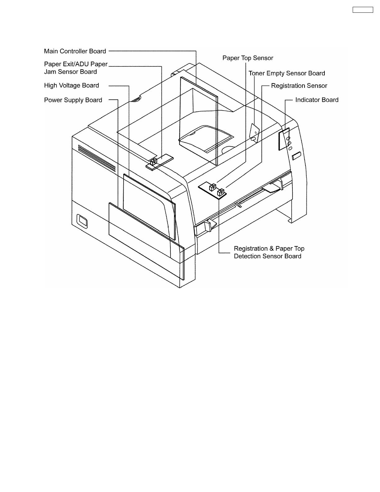
1.5. Electrical Components and Sensor Boards
13
KX-P7100
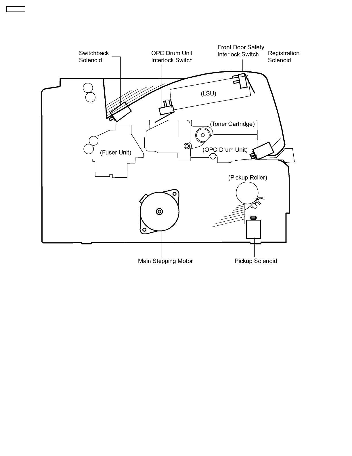
1.6. Switches and Solenoids
14
KX-P7100
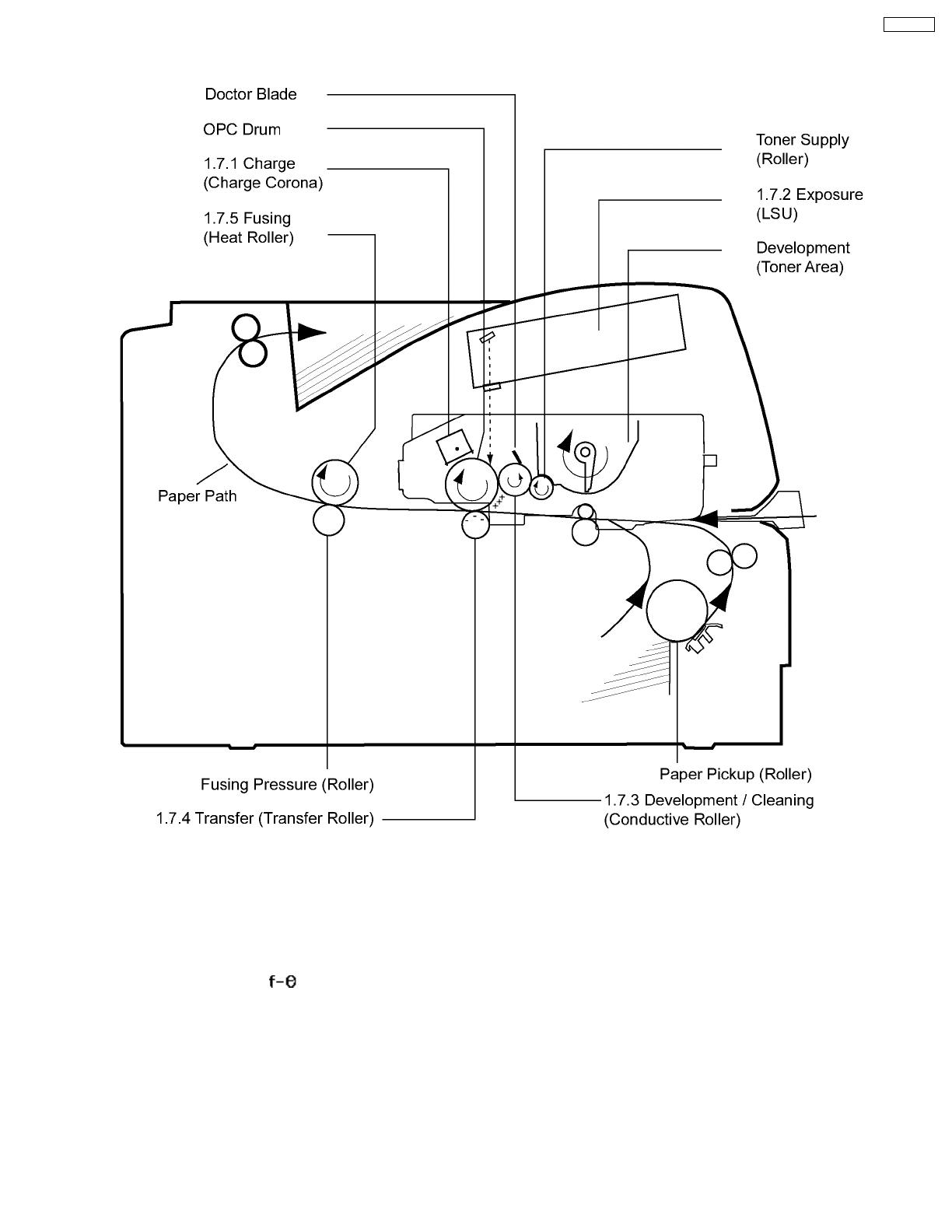
1.7. Print Process
1.7.1. Charge
The charge corona applies a high, uniform positive charge to the surface of the organic photoconductor ( OPC ) drum. The charge
level is approximately 900 VDC and remains because the OPC drum has a high electrical resistance when concealed in darkness.
1.7.2. Exposure
The laser beam passes through the collimator lens, is reflected by the polygon mirror, and is focused onto the drum after passing
through an image-forming ( ) lens and a reflectionmirror. Wherever the laser beam strikes the drum, the positive charge
dissipates. A latent electrical image of two different voltages potentials, which corresponds to the original page, is formed on the
OPC drum.
1.7.3. Development / Cleaning
Development:
Non-magnetic toner is supplied to the conductive roller by the toner supply roller. The toner on the conductive roller is positively
charged by friction with the toner supply roller, and the doctor blade ensures a thin layer on the surface of theconductive roller.
Wherever the conductive roller touches the drum, the positively charged toner is attracted to the latent image on the drum, and the
latent image is converted to a visible toner image. A bias voltage of approx. 350 VDC is appliedto the conductive roller to achieve
maximum print quality.
15
KX-P7100

Cleaning:
After transfer, residual toner remains on the drum surface, and for next printing, the residual toner reaches to the development area
via charge and exposure. The charge level of the OPC corresponds to the white background is +900VDC, andthe bias voltage of
the conductive roller is approx. +350VDC. Therefor the positively charged residual toner on the OPC drum is attracted and collected
to the conductive roller. The charge level of OPC after exposure is +100VDC. So,the printing area of the OPC is cleaned.
1.7.4. Transfer
As the paper is fed between the drum and the transfer roller, a high negative charge is applied to the back of the paper. The positive
toner particles are then attracted from the drum surface to the paper. After transfer, the paper is separatedfrom the drum surface
by the curvature of the drum.
1.7.5. Fusing
The paper passes through the fuser rollers and is subjected to heat and pressure. The fusing temperature is approximately 190°C
( 382.5°F ), and the pressure is approximately 0.36kg/cm ( 3.53N/cm ). This bonds,or fuses, the toner into the paper.
16
KX-P7100

1.8. Paper Feed
Media Tray
The main motor drives the pickup roller after the pickup solenoid is energized, which engages the pickup roller clutch and feeds a
sheet of paper. The paper is pushed to the paper feed roller, which overdrives the paper slightly causing a buckleto ensure the
paper is aligned with the stationary registration roller.
While triggering the registration sensor notifying the CPU paper is ready to feed. The paper at this point is the same as manual
feed.
Manual Feed
when paper is inserted, it activates the registration sensor. At the porter time, the CPU energizes the registration solenoid that
allows the registration roller to rotate, feeding paper to the top sensor.
17
KX-P7100

1.9. Laser Scan Unit ( Exposure )
1.9.1. Operation Theory
The light beam from the laser diode ( light source ) is modulated by the digital signal (nVIDEO) and converted to parallel light waves
by the collimator lens. The beam is then sent to the rotating polygon mirror (polygon scanner), where it is reflectedthrough the
lens and then focused onto the OPC drum surface. The diameter of the beam is about 80 µm, and the light moves across the
surface of the OPC drum in the scanning directionof right to left. As the drum rotates ( sub-scans ), a static image is formed where
the laser beam touches the drum surface.
The laser beam is also deflected to the timing sensor. This sensor controls the start timing of scanning on the drum, providing a
consistent left margin. The CPU uses the timing sensor to detect abnormal signals.
1.9.2. Laser Beam
The laser beam is pulsed on and off by the digital signal (nVIDEO) to form a latent image of two different voltage potentials on the
drum, as shown below.
Laser Diode Specification
Item Minimum Standard Maximum
Oscillation Wavelength 770 785 800 nm
Output Light Power
(OPC Drum Surface) 0.315 0.350 0.385 mW
18
KX-P7100
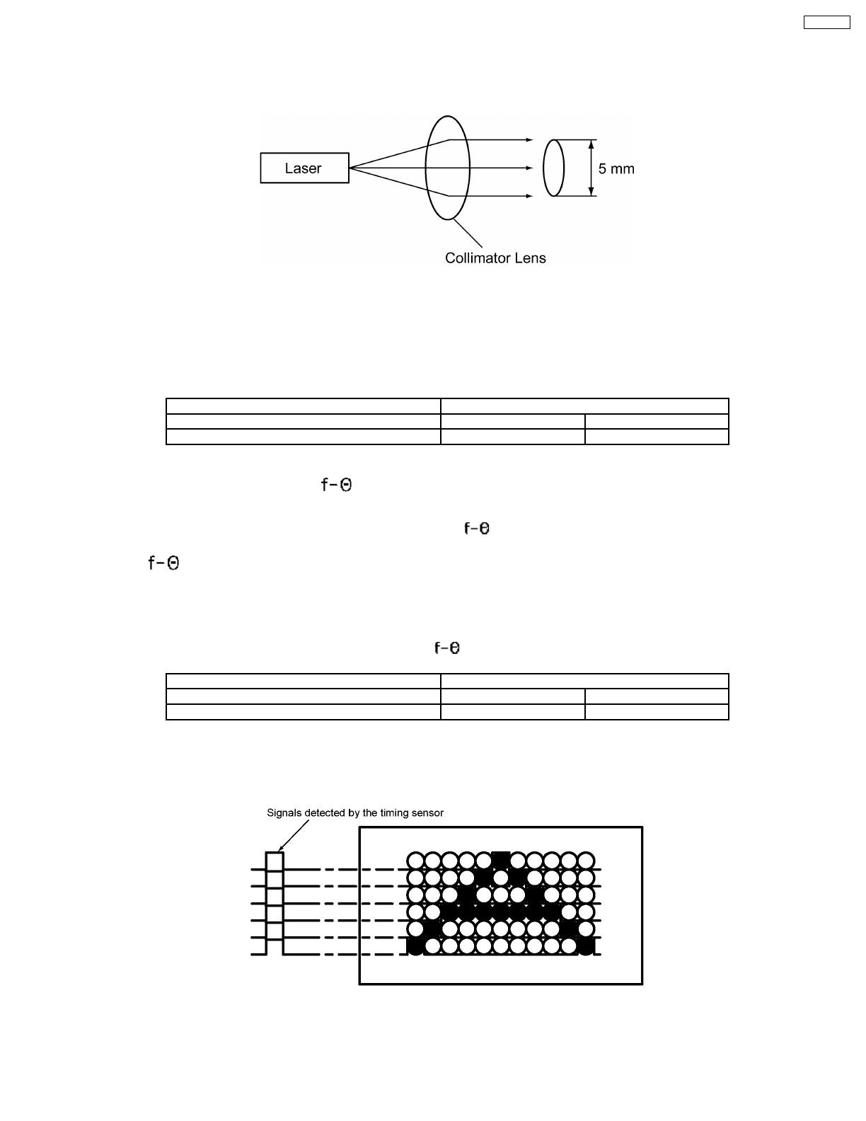
1.9.3. Collimator Lens
The collimator lens converts light from the laser diode to parallel light. This aids in scanning and provides better convergence to a
dot.
1.9.4. Polygon Scanner
The polygon scanner consists of a 6-sided mirror directly driven by a brushless DC motor at a rate 20,078.74 rpm. The laser beam
is reflected across the OPC drum by the mirror faces and produces the scan. One mirror face is equal to one main scan.This unit
features stable line scanning speed, precision mirror surface reflection angle, reflect-free surfaces, and instant start.
Polygon Scanner Specifications
Item Specification
Mirror 6 faces
Revolution 20,078.74 rpm
1.9.5. Cylindrical Lens and Lens
Each of the polygon mirror surfaces has a slight imperfection. This prevents the beam from scanning the OPC drum surface at the
constant interval in the sub-scan direction. The cylindrical lens and lens are used for correcting this uneven laser scanning.
1.9.6. Lens
This lens ensures that the beam scans across the surface of the OPC drum at a constant rate. The beam is refracted to parallel
light as it passes through the lens to ensure that the dots at the edge of the drum and at the center of the drum areequally spaced.
This lens also provides a set focal length for laser beam.
Specifications
Item Specification
Scanning Width 207.43 mm
Focusing Light Spot Size 80 x 90 µm
1.9.7. Timing Sensor
This sensor detects the laser beam and determines the start timing for scanning. A pin photodiode is used as the timing sensor.
19
KX-P7100

1.10. Fuser Unit
A 600W heat lamp ( halogen lamp ) heats the surface of the teflon-coated heat roller to approximately 190°C ( 374°F ), a thermistor
monitors the heat roller temperature, and the CPU controls the ON/OFF timing of the lamp.
The thermostat is mounted 2.5mm away from the heat roller. If the ambient temperature reaches 180°C ( 356°F ), the thermostat
is opened, and power is removed from the heat lamp. The surface of the thermostat is not as hot as thatof the heat roller. When
the thermostat opens, the surface of the heat roller may reach 200°C ( 382°F ), and the system displays E30. If the thermistor
opens, the system displays E32. If by chance the thermostat malfunctions a thermalfuse opens.
The pressure roller is kept in contact with the heat roller through 2 pressure springs, which apply a pressure of approximately 0.36
kg/cm ( 3.56 N/cm ). Drive is supplied from the main motor via intermediate gears.
20
KX-P7100
/