Page is loading ...

AQUASMART 5 RP v1.2
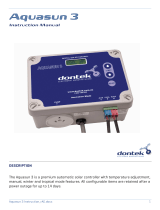
AQUASMART 5 RP
Instruction Manual
DESCRIPTION
The AQUASMART 5 RP is a premium automatic solar controller with temperature adjust
ment, manual,
cooling and standby mode features.
Wireless remote roof sensor - Solar Panel (PV)

AQUASMART 5 RP v1.2 2
INSTALLATION INSTRUCTIONS
THIS APPLIANCE IS NOT INTENDED FOR USE BY YOUNG CHILDREN
OR INFIRM PERSONS WITHOUT SUPERVISION. PLEASE ENSURE
THAT YOUNG CHILDREN ARE SUPERVISED TO ENSURE THAT THEY
DO NOT PLAY WITH THE APPLIANCE.
CONTROLLER MOUNTING
Find a suitable location to mount the control box
*radio note
.
Ideally,
as with all pool equipment, it should be installed out of direct
weather and no closer than 3 metres from the water’s edge and a
minimum 600mm above ground. Fix the mounting bracket to a
solid structure and slide the controller on, keeping in mind that
the power cable is 1.8m long and should be plugged directly into
a general power outlet, not into an extension lead.
PUMP CONNECTION
The solar collector pump plugs into the 240V socket
labelled PUMP.
The maximum load is 9.98 AMPS at 2395W.
POOL SENSOR
The pool sensor must be fitted into the heating circuit, as
close to the pool as practical, preferably in a position out of
direct sunlight. It is recommended that a 14.5mm hole be
drilled in the side of the PVC pipe (not the top of the pipe
where water will collect). This can be carried out using a
Dontek PD01 grinding drill or a small pilot hole can be
drilled with a 14.0mm drill-bit used spinning in a counter
clockwise direction to minimize the chance of shattering
pipe. Insert the grommet into the pipe and gently push in
the sensor barb. Ideally ~30cm of the cable from the
sensor should be tied to the shaded side of the pipe to
prevent extreme ambient conditions leeching into the
sensor via the copper in the cable. The blue sensor plug is
to be fitted to the plug socket marked POOL.
REMOTE TEMPERATURE ROOF SENSOR
The roof temperature sensor must be fitted into a small
piece of solar collector or equivalent and attached to the
roof. The best location is within an arm's length of the
gutters edge of the house or shed as long as the sensor
end is not shaded and is on a roof of similar aspect of the
main collector. It must not be fitted on top of the solar
collector or fitted to high points on the roof like Ridge
Capping as false readings will be detected.
This unit has been designed to eliminate the need to run a
temperature sensor cable from the solar controller to the
roof; this is replaced by a solar powered transmitter that
transmits the roof temperature. The roof temperature
sensor cable is connected on the inside of the radio remote
temperature transmitter in a screw in socket. Test for site
suitability (*radio note) then mount the radio remote
temperature transmitter on the gutter ensuring the solar
panel (PV) faces north and the antenna points up
(Vertical), if the antenna faces down then water may enter
the box through the power entry / sensor entry hole and
void the warranty.
*RADIO NOTE: RADIO TRANSMITTER SPECIAL
CONSIDERATIONS
Do not permanently fix the radio transmitter until good
reception is achievable (See site AQUASMART RP
Instruction test); do not mount the AQUASMART in a
position where reception of radio signals may be difficult,
avoid mounting near other electrical equipment. The range
is 100m with no obstructions and with no interference
from other transmitters or sources of electrical noise. Also
be aware that equipment installed afterwards may also
interfere with radio reception. Transmission may not occur
through objects such as steel, aluminium, re-enforced
concrete and large bodies of water (e.g. pump room under
a pool). Line of sight is the ideal situation but not always
possible, the antennas should always remain vertical. Echo
cancellation or ghosting may occur, which will prevent the
signal being received reliably. If the Aquasmart RP is to be
installed in a metal shed there may be reception issues
and the controller may need to be optioned antenna
extension or moved outside.
Other Notes
: Both the
transmitter and receiver are tested as a set to 100 metres;
do not mix different transmitters with different receivers.
Read and understand this manual before going on site.
Ensure the customer also understands the workings of the
controller before leaving the site.
SITE TEST
Place the radio transmitter in the approximate location.
Select test mode on the AQUASMART by holding the DOWN
button for 3 seconds while you apply power, this activates
a mode where only roof temperature transmissions are
shown. Once you release the down button the AQUASMART
screen indicates RX TEST. Verify that every 5 seconds the
LCD displays the temperature (e.g. TEST 32°). Check that
this sequence is repeated for about half a minute and
ensure no transmission is missed. If a transmission is
missed it may be due to an echo or ghosted signal, move
the location of the radio transmitter or the location of the
Aquasmart RP and retest. If no transmission is missed
mount the transmitter and repeat the test, check that no
transmission is missed for 2 minutes. Turn OFF power to
the AQUASMART and then permanently mount the radio
transmitter. Return to the AQUASMART restart the RX TEST
and ensure it continues to receive the transmission, move
the location of the AQUASMART if required. Permanently
mount the AQUASMART when satisfied that the
AQUASMART is receiving the transmissions consistently.
During normal operation the software allows for missed
transmissions, but when more than 50 minutes elapse
without a transmission then the temperature value will
timeout and will be indicated by the “Waiting for roof
transmission” message.

AQUASMART 5 RP v1.2
3
REPORTED TRANSMITTER FAULTS
If the following messages are displayed, then action is to
be taken to rectify the fault(s)
"WAITING FOR ROOF TRANSMISSION"
The AQUASMART cannot receive a roof temperature from
the radio transmitter or more than 50 minutes have
elapsed since the last transmission, check installation as
per instructions.
.
"ROOF SENSOR DISCONNECTED"
Check that the temperature sensor is firmly connected to
the terminals. Cable joints must also be soldered and
sealed (preferably with heat shrink). An unbroken but
damaged cable can also cause this fault
OPERATING INSTRUCTIONS
LCD SCREEN
The LCD screen displays the pool and roof temperatures,
solar temperature limit, pump on status, on/off/locked-out
status and the time of day & date (clock).
LCD INDICATORS
There are arrow icons on the LCD screen that point to
current mode text on the label.
MODE BUTTON
Pressing this button changes to the next mode of
operation in the following order; Heating / Manual /
Standby.
Once the mode button is no longer being pushed then the
selected mode of operation is automatically saved.
Heating mode (Auto)
is the normal operating mode for
heating the pool.
Manual mode
is for testing the pump installation on a cold
or cloudy day. Once manual mode is selected the pump will
start. After manual mode time-outs, unit will return to the
previous mode.
Standby mode
of operation is for off-season maintenance
or if pool heating is not required. This is a better option
than turning off the controller as it will flush treated pool
water through the solar system as well as prolong pump
bearing and mechanical seal life. The pump will run for 3
minutes each day from when the Standby mode was
selected or at 10am if the time-clock mode was selected
.
**The factory default for SOLAR MODE is Heating
MODE
↑
AND
↓
BUTTONS (TEMPERATURE SETTING)
Adjusting the temperature limit will allow the controller to
heat the pool until the temperature limit +½°C is achieved,
heating will then remain off until the sample wait period
expires, if no sample wait period is active the heating will
remain off until the pool temperature drops ½°C below the
temperature limit setting, due to rounding the actually
heating hysteresis is ±½°C.
The ability to solar heat the pool will depend on weather
conditions.
** The factory default for SOL. LIMIT is 30°C
ENTER BUTTON
Pressing the ENTER button will turn on the LCD backlight,
pressing the ENTER button while the backlight is lit will
enter the SETTINGS MENU;
The following will be displayed;
1) EXIT
The menu system can be navigated using the
↑
or
↓
buttons, all selectable and changeable values will flash on
the LCD screen. Press the ENTER
button to accept the
currently displayed (flashing) item.
All menu items are shown below;
1) EXIT
2) CLOCK
3) SYSTEM
1) EXIT
Press ENTER on this menu to return to automatic
operation.
2) CLOCK
When selecting the clock you will have to set the time of
day.
3) SYSTEM
System sub-menu;
EXIT
LCD TIME
HOURS
EXIT
- Press ENTER on this menu to return to automatic
operation.
LCD TIME
– Adjust the number of seconds the backlight
remains on after the time a button was pressed. (Select
NONE for always on.)
HOURS – is for hours of solar operation (
24hr)
first
selecting the start time in hour intervals
(6:00 – 12:00)
Then the end time
(12:00 – 21:00)
**
Factory default for
installer setup is run from 12:00-12:00 (24hrs).

AQUASMART 5 RP v1.2 4
INSTALLER SETUP:
TO ASSESS MENU PRESS ENTER SCROLL DOWN TO SETTINGS AND PRESS THE
MODE BUTTON WARNING PROFESSIONAL ONLY SETTINGS!!
RESTORE DEFAULTS – Restore back to factory defaults
RUN – When the roof temperature rises to pool + run then
the solar will start.
END – When the roof drops below pool + end then the solar
will stop
BOIL? - Anti boil function (on supported controllers) when
switched to ON will start the pump when the roof
temperature rises to the selected temperature and
operates for 5 minutes every 15 minutes until the roof
temperature rises above the selected temperature.
PIPE PROTECTION - For use when solar collectors are
flooded, flat and will require a wetted roof sensor for this
mode.
CAL – Calibrate the pool sensor.
ROOF SENSOR – Allows the use of a wired roof sensor cable
temporarily, if the PV Unit has been damaged
NOTES:
1. If any of the menu items are left unattended for 3
minutes the menu will time out and automatically save
all settings and return to automatic operation.
2. If a sensor fault is detected the controller will display
which sensor and what the fault is.
3. Should power be interrupted for any reason, the
controller will resume normal operation when power is
restored, all information will have been kept for 10
days.
4. If the controller has stopped the pump and is
displaying a higher temperature than expected it may
be caused by a pump which is failing to prime, check
the pump and if necessary prime the pump as per the
pump manufacturers’ instructions then reset the
controller by turning it off/on.
5. Maximum combined rated output load for the 240V
socket(s) is 9.98 Amps / 2395 Watts.
6. Degree of protection against moisture: IP33.
WARRANTY
This range of product is covered by a limited 3 year warranty against component failure or
faulty workmanship from the date of installation.
Faulty units should be returned in the first instance to the dealer from which the unit was
purchased.
Damage to the unit due to misuse, power surges, lightning strikes or installation that is not in
accordance with the manufacturer’s instruction may void the warranty.
Warranty does not include on-site labour or travel costs to or from installation site.
If the power cord is damaged, do not use the controller; return the unit to the supplier for repair.
CUSTOMER RECORD
(To be retained by the customer)
DEALER/INSTALLER NAME
SERIAL NUMBER
DATE INSTALLED
For service assistance visit
www.dontek.com.au
Dontek Electronics Pty Ltd
PO Box 239, Bayswater VIC 3153 Australia
Phone: +613 9762 8800 Email: sales@dontek.com.au
/