Page is loading ...

Aquasun 3 CD Instruction rB2.docx
1
Instruction Manual
DESCRIPTION
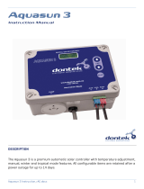
The Aquasun 3CD is a premium automatic solar controller with temperature adjus
tment,
manual, winter and tropical mode features. This unit is fitted with current detection on the
auxiliary power socket; the solar pump can only operate if the current load on the
controllers auxiliary socket is within a certain range (e.g. filter pump
is operating and
primed).

Aquasun 3 CD Instruction rB2.docx
2
INSTALLATION INSTRUCTIONS
CONTROLLER
Find a suitable location to mount the control
box. The controller should be installed out of
direct weather and no closer than 3 meters
from the water’s edge. Lift up the two
mounting tabs and use two appropriate
screws to mount the control box to the wall,
keeping in mind that the power cable is 1.8m
long and should be plugged directly into a
general power outlet, not into an extension
lead. Do not drill through the box.
SOLAR PUMP
The solar pump plugs into the left side
240Vac socket marked as PUMP. Note that
the solar pump can only operate when the
auxiliary power socket uses sufficient power
to trigger the current detection circuit, this
detection trigger point can be adjusted (see
Installer Settings).
FILTRATION PUMP
An Ioniser/Chlorinator or equivalent pump
timer is to be plugged into the right hand side
240V socket (auxiliary) located under the
POOL & ROOF sensor inputs, the filtration
pump plugs into the Ioniser/Chlorinator pump
socket.
TEMPERATURE SENSORS
The pool temperature sensor must be fitted
into the suction line of the
filtration
pump, as
close to the pool as practical, preferably in a
position out of direct sunlight. It is
recommended that a 14.5mm hole be drilled
in the PVC pipe, this can be carried out using
a Dontek PD01 grinding drill or a small pilot
hole can be drilled and a 14.0mm drill-bit
used spinning in a counter clockwise direction
to minimize the chance of shattering pipe.
Insert the grommet into the pipe and gently
push in the blue/grey sensor barb. The blue
sensor plug is to be fitted to the plug socket
marked POOL, in some cases there is some
benefit to cable tie 30cm of wire from the
pool temperature sensor to the pipe and
insulate this section (some ambient
differences can travel up the tinned copper
wire and affect the sensor reading).
The
roof temperature sensor must be fitted
into a small piece of solar collector or
equivalent and attached to the roof. The best
location is within an arm’s length of the
gutters edge of the house or shed as long as
the sensor end is not shaded and is on a roof
of similar aspect of the main collector. It
must no
must nomust no
must not
tt
t be fitted on top of the solar
collector or fitted to high points on the roof
like Ridge Capping as false readings will be
detected.
The red sensor plug is to be fitted to the right
hand socket marked ROOF. Keep in mind that
it is of the utmost importance to keep the
roof temperature sensor cable as short as
possible as this will assist in the longevity of
the sensor and controller in the event of
electrical storm activity and power surges.
All temperature sensor cables must NOT be
All temperature sensor cables must NOT be All temperature sensor cables must NOT be
All temperature sensor cables must NOT be
run parallel to power cables and should
run parallel to power cables and should run parallel to power cables and should
run parallel to power cables and should
never be cable tied to power cables.
never be cable tied to power cables. never be cable tied to power cables.
never be cable tied to power cables. All
cable run lengths should be less than 50m if
possible. Cable ties should be used to fasten
the sensor cable to the cold water inlet pipe
making sure that the ties are approximately
10mm from PVC fittings. Cable ties should be
tightened only firm, over tightening can cause
breaks in the outer PVC if not careful. If the
cable is to be run under ground a conduit
must be used to protect the wire and there is
to be no cable joins within, conduit ends must
mustmust
must
be sealed to prevent water ingress.
Any excess cable should be removed and
Any excess cable should be removed and Any excess cable should be removed and
Any excess cable should be removed and
re
rere
re-
--
-fitted ensuring that the wire ends are
fitted ensuring that the wire ends are fitted ensuring that the wire ends are
fitted ensuring that the wire ends are
tinned with solder.
tinned with solder.tinned with solder.
tinned with solder.

Aquasun 3 CD Instruction rB2.docx
3
AQUASUN 3CD INSTALLER SETTINGS
PUMP LOAD SETTING
*** IMPORTANT *** The controller will not
operate and will display a ‘INSTALLER MUST
SET PUMP LOAD’ message. The correct Load
setting is required for this controller to pick
up a pump which is failing to prime. After
setting the load values test by starting the
solar pump in Manual Mode and ensure that
the solar pump will switch off if the filtration
pump fails to provide water.
Filtration Pump Load Automatic Setting:
There are 2 methods for setting the load
detection of the filtration pump.
For
automatic setting ensure the filtration pump
is operating and primed. Then simply hold the
UP button then press SELECT
, the unit will
then display the pump’s load value and
automatically sets the threshold levels and
returns to automatic operation, if the current
draw of the filtration pump drops below this
level then the solar pump is forced to switch
off.
Advanced Settings: To select the advanced
settings, hold the DOWN button then press
SELECT.
FILTRATION PUMP LOAD MANUAL SETTINGS
If setting the load value, please ensure your
filtration pump is connected to the auxiliary
power socket (right hand side) and that the
filtration pump is primed and if it’s a variable
speed pump ensure the filtration pump is
operating at the required speed. After
releasing the SELECT button the LOAD=xxx
value is displayed for 5 seconds, take note of
this value. When the LCD screen displays
RUN=>xxx it indicates the minimum load
required to allow solar to run, set this value
10% lower than the displayed LOAD value and
press SELECT. The next value to adjust is
TRIP> this is the overload value, when the
filtration pump draws too much power (e.g. a
variable speed pump operating too fast) then
the solar pump is stopped. *Default is a
RUN=>20 and trip >99.
Once the Advanced settings have been
adjusted all the above settings will be saved
and the unit will restart. Re-adjust the
temperature limit if required.
ADJUSTABLE DIFFERENTIAL
Special note: Adjusting these values to any
setting other than the defaults may adversely
affect the performance of this controller. To
adjust the differentials hold the UP button
while applying power to the unit. The first
item prompted is to set the solar gain start
temperature (RUN° x) this setting allows the
pump to start if the roof temperature exceeds
the pool temperature by this value, adjust
with the UP/DOWN button, press SELECT to
accept. Next you will be prompted to set the
differential hysteresis (END° x) which turns
the pump off when roof temperature is less
than the pipe temperature plus this value,
adjust with the UP/DOWN button, press
SELECT to accept. Default values are 8° for
RUN and 4° for END, these are the optimal
values for maximum efficiency, some coastal
locations may benefit from a reduced run
value of 6°C for RUN and 4°C for END.
FACTORY TEST
To run the factory test, hold the SELECT
button when first applying power, the unit will
perform a series of self-diagnostic functions
with the pump running.
If there are any faults they will be reported on
the display before the unit restarts into
normal operation.
Note: that this will force all settings to a
factory default state. Re-enable time-clock if
required also set the Pump Load value,
temperature limit and operating mode to
their required settings.

Aquasun 3 CD Instruction rB2.docx
4
AQUASUN 3CD INSTALLATION
INSTRUCTIONS
TEMPERATURE LIMIT
To adjust the pool limit simply press the UP
button to increase or the DOWN button to
decrease the desired temperature. The
controller will automatically choose to run the
pump based on solar gain (i.e. sun shining &
roof is hot), once the pools desired
temperature is exceeded by ½°C the pump is
stopped until the pool temperature drops
½°C below the temperature limit setting.
MODE OF OPERATION
Pressing the SELECT button once will display
the current mode of operation, pressing it
again or holding it will select the next
available mode of operation.
The available modes are SUMMER, MANUAL,
WINTER, TROPICAL and SETTINGS.
Summer mode
Summer modeSummer mode
Summer mode
is the normal operating mode
for heating the pool.
Manual mode
Manual modeManual mode
Manual mode
is for testing the pump
installation on a cold or cloudy day. Once
manual mode is selected the pump will start
if it has been off, or stop if it has been on
(running). After 30 minutes manual mode will
time-out and return to the previous operating
mode. Note that Manual ON requires an
operating filtration pump in the auxiliary
power socket.
Winter mode
Winter modeWinter mode
Winter mode
of operation is for off-season
maintenance or if pool heating is not required
(AWAY MODE)
. This is a better option than
turning off the controller as it will flush
treated pool water through the solar system
as well as prolong pump bearing and
mechanical seal life. The pump will run for 3
minutes once a day 3 minutes after the
filtration pump has started.
Tropical mode
Tropical modeTropical mode
Tropical mode
of operation is for situations
where the pool water overheats due to direct
heating from the sun. When the roof is 4°C
cooler than the pool temperature, the pump is
started (this will most likely occur at night
and therefore requires the filtration to run at
night) and will attempt to cool the pool to 1°C
above the temperature limit. Normal heating
will occur the next day if the pool drops below
the set temperature limit by 1°C.
Settings mode
Settings mode Settings mode
Settings mode is
for setting the unit into
time-clock operation.
When you select this option you will be asked
if you wish to use the clock feature (CLK?
ON/OFF). If you select OFF then the controller
will not work as a time-clock model and will
allow the solar pump to run whenever there is
solar heating available and if the filtration
pump is operating. If you select ON you will be
prompted to set the time of day, the
controller will work in time-clock mode and
the solar pump is prevented from starting
outside of the set hours (Unless tropical
mode is selected). Set the time of day in 24
hour format, note there is an AM/PM
indication to avoid incorrect settings.
Seconds are automatically set to zero.
Once the time is set select the START hour
from 6am till noon, default is 9am which
means the solar pump cannot start before
9am.
Now select the END hour from 15 (3pm) till 21
(9pm), default is 19 (7pm) which means the
solar pump will stop at 7pm.

Aquasun 3 CD Instruction rB2.docx
5
NOTES
1. If a sensor fault is detected the
controller will display which sensor
failed (POOL and/or ROOF) and the type
of failure.
2. After a power outage all configurable
items are retained & the clock (if used)
will keep time for up to 14 days.
3. The sensor cable with the red trace is
the positive and is fitted to the right
hand side of the plug when looking at
the plug screws, incorrect polarity will
be displayed as a short circuit or
reversed fault.
4. A filtration pump that uses too much
current can bring up an OVERLOAD
condition. Disconnect power & check
the condition of the filtration pump, this
will prevent the solar pump from
running.
5. FILTER PUMP OFF, CANNOT START - The
solar pump can't be started because
the filter pump is not operating or not
drawing water from the pool or there is
a blockage (i.e. filter). The value for
RUN=> may be set too high.
6. When the auxiliary power socket
detects the filtration pump starting it
will perform a 3 minute checking
sequence that ensures there is suitable
temperature & water flow before the
solar pump will start. When the
filtration pump is stopped the solar
pump is also stopped.
7. Pump load values displayed is relative
to how much power is consumed by the
pump, note that variable speed pumps
tend to display higher than expected
values.
8. Maximum rated output load for the
240V socket is 9.98 Amps / 2395 Watts.
9. Degree of protection against moisture:
IP23
NOTES

Aquasun 3 CD Instruction rB2.docx
6

Aquasun 3 CD Instruction rB2.docx
7

Aquasun 3 CD Instruction rB2.docx
8
WARRANTY – AQUASUN 3 CD
This range of product is covered by a limited 3 year warranty against component failure or faulty
workmanship from the date of installation. A faulty unit should be returned in the first instance to
the dealer from which the unit was purchased.
Damage to the unit due to misuse, power surges, lightning strikes or installation that is not in
accordance with the manufacturer’s instruction may void the warranty.
Warranty does not include on-site labour or travel costs to or from installation site.
If the power cord is damaged, do not use the controller; return the unit to the supplier for repair.
CUSTOMER RECORD
(To be retained by the customer)
(To be retained by the customer)(To be retained by the customer)
(To be retained by the customer)
DEALER/INSTALLER NAME
SERIAL NUMBER
DATE INSTALLED
For service assistance phone 1300 130 693
Dontek Electronics Pty Ltd
www.dontek.com.au
PO Box 239, Bayswater VIC 3153 Australia
Phone: +613 9762 8800 Fax: +613 9762 8874 Email: sales@dontek.com.au
/


