SICK TTK70/TTK50 Linear motor feedback systems Product information
- Type
- Product information

Product information
ttK70/ttK50
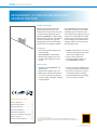
mEaSurEmEnt of PoSition and SPEEd WitH maXimum PrEciSion
Linear motor feedback systems

ENCODERS | SICK 8015022/2021-05-27
Subject to change without notice
2
TTK70 LINEAR ENCODERS
Product description
Precision, speed and dynamics play
a particularly important role in the
measurement of linear movements. The
compact linear measurement system
TTK70 with HIPERFACE
®
or SSI interface
fullls all these properties. The magnetic
principle of operation, the long mea-
suring lengths, and the extremely high
resolution open up all kinds of applica-
tion possibilities for absolute position
and speed recording. The non-contact
measuring system consists of a com-
pact read head and magnetic tape. The
read head is responsible for recording
position values. The magnetic tape is
the measuring element and features a
magnetic division into an incremental
and an absolute track.
At a glance
• Non-contact absolute position and
speed recording
• With HIPERFACE
®
or SSI interface
• Measurement lengths of up to 4 m
• For high traversing speeds of up to
10 m/s
• Reliable measurements, even in the
event of contamination and conden-
sation on the magnetic tape
• Small, compact read head
• Certied according to SIL2 and
PL d (HIPERFACE
®
interface)
Your benets
• Available with the HIPERFACE
®
and
SSI interfaces
• Measurement lengths of up to 4 m
• Maintenance and wear-free thanks to
non-contact measurement principle
• Compact design, low weight, and high
traversing speed
• Immune to ambient conditions such
as contamination and condensation
• No need for a reference run due to
the absolute position recording
• Certication allows for easy integra-
tion into a safe drive system
Encoders
LINEAR ENCODERS
TTK70
Subject to change without notice
.
MEASUREMENT OF POSITION AND SPEED WITH
MAXIMUM PRECISION
Additional information
Fields of application. . . . . . . . . . . . . . .3
Detailed technical data . . . . . . . . . . . .3
Ordering information . . . . . . . . . . . . . .5
Dimensional drawings . . . . . . . . . . . . .6
PIN and wire assignment . . . . . . . . . . .8
Order note for magnetic tape length .8
Position tolerance. . . . . . . . . . . . . . . . .8
Recommended accessories . . . . . . 19
- www.sick.com/TTK70
For more information, simply enter the link or scan the QR code and get direct access to
technical data, CAD design models, operating instructions, software, application examples, and
much more.
A
B
C
D
E
F
H
I
J
K
L
M
N
O
P
Q
R
S
T

ENCODERS | SICK8015022/2021-05-27
Subject to change without notice
3
LINEAR ENCODERS TTK70
Fields of application
• Linear motors • Pick & Place applications
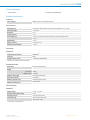
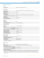
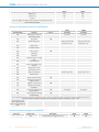
Detailed technical data
Features
Items supplied
Magnetic tape not included with delivery
Performance
Measuring step
0.244 µm For interpolation of the sine/cosine signals with, e. g., 12 bits
Measuring length
≤ 3,920 mm
Resolution
1 µm
Length of period
1 mm
Traversing speed
≤ 10 m/s, up to which the absolute position can be reliably produced
1.3 m/s
Repeatability
< 5 µm
System accuracy
± 10 µm (+20 °C)
Measured value backlash
< 10 µm
Interfaces
HIPERFACE
®
Communication interface
HIPERFACE
®
1)
Code type
Binary
Available memory area
1,792 Byte (E
2
PROM 2048)
1)
SSIinterface described in publication 8013375.
Mechanical data
Dimensions
See dimensional drawing
Weight
Read head 0.08 kg
Magnetic tape 0.18 kg/m
Magnetic strip length
See ordering information
Read head material
Zinc diecast
Material, magnetic tape
17410 Hard ferrite 9/28 P
Material mounting tape
Stainless steel
Electrical data
HIPERFACE
®
Supply voltage
7 V DC ... 12 V DC
Recommended supply voltage
8 V DC
Operating current
≤ 65 mA (without load)
1)
Connection type
Male connector, M12, 8-pin
Cable, 8-wire, 0.5 m
1)
100 mA approx. during adjustment.
A
B
C
D
E
F
H
I
J
K
L
M
N
O
P
Q
R
S
T

ENCODERS | SICK 8015022/2021-05-27
Subject to change without notice
4
TTK70 LINEAR ENCODERS
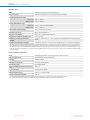
Ambient data
EMC
According to EN 61000-6-2 and EN 61000-6-3
1)
Enclosure rating
IP67, with mating connector inserted (according to IEC 60529)
Operating temperature range
Read head –30 °C ... +80 °C
Magnetic tape –20 °C ... +100 °C
Storage temperature range
Read head –40 °C ... +85 °C, without package
Magnetic tape –30 °C ... +100 °C
Permissible relative humidity
100 %, condensation permitted
Resistance to shocks
30 g, 6 ms (EN 60068-2-27)
Resistance to vibration
20 g, 10 Hz ... 2,000 Hz (EN 60068-2-6)
Temperature coecient magnetic tape
(11 ± 1) µm/K/m
Maximum permitted ambient eld
strength
< 3 kA/m ... 4 kA/m (3.8 mT ... 5 mT), to guarantee compliance with the quoted accuracy
values
2)
Maximum permitted eld strength
< 150 kA/m (< 190 mT), to ensure that the magnetic tape is not permanently damaged
1)
According to the listed standards, EMC is guaranteed if the motor feedback system is connected to the central grounding point of the motor controller via a
cable shield and the encoder housing lays over a large area of the motor potential. If other shielding concepts are used, users must perform their own test.
2)
The maximum permitted external eld inuence is reached when the position value deviates from the original value (without external eld inuence) by more
than 5 μm. This value is reached when, at the sensor location, a eld strength of 3 kA/m to 4 kA/m (3.8 mT to 5 mT) occurs in addition to the eld strength of
the magnetic tape.
Safety-related parameters
Note
The following parameters are only valid for SIL2 certied versions
Safety integrity level
SIL2 (IEC 61508), SILCL2 (EN 62061)
1)
Category
3 (EN ISO 13849)
Maximum demand rate
Continuous (analog signals)
Performance level
PL d (EN ISO 13849)
PFH
D
: Probability of dangerous failure per
hour
2.02 x 10
-8
2)
T
M
(mission time)
20 years (EN ISO 13849)
Safety-related accuracy
± 25 mm, = ± 1/4 pin length
Safety-related measuring step
0.25 mm
1)
For more detailed information on the exact conguration of your machine/unit, please consult your relevant SICK branch oce.
2)
The specied values apply to a diagnostic coverage rate of 90%, which must be achieved by the external drive system.
A
B
C
D
E
F
H
I
J
K
L
M
N
O
P
Q
R
S
T

ENCODERS | SICK8015022/2021-05-27
Subject to change without notice
5
LINEAR ENCODERS TTK70
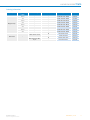
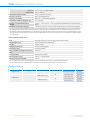
Ordering information
System part Magnetic strip
length
Connection type Safety system Type Part no.
Magnetic tape
0.5 m – – MVM-0M5-2MC-MKLB 6037415
1 m – – MVM-01M-2MC-MKLB 6037417
1.5 m – – MVM-1M5-2MC-MKLB 6 037418
2 m – – MVM-02M-2MC-MKLB 60 3741 9
2.5 m – – MVM-2M5-2MC-MKLB 6037420
3 m – – MVM-03M-2MC-MKLB 6037421
3.5 m – – MVM-3M5-2MC-MKLB 6037422
4 m – – MVM-04M-2MC-MKLB 6037423
Read head –
Cable, 8-wire, 0.5 m
l
TTK70S-HXJ0-K02 1099701
– TTK70-HXJ0-K02 1063567
Male connector, M12,
8-pin
l
TTK70S-HXA0-K02 1099700
– TTK70-HXA0-K02 10374 3 4
A
B
C
D
E
F
H
I
J
K
L
M
N
O
P
Q
R
S
T

ENCODERS | SICK 8015022/2021-05-27
Subject to change without notice
6
TTK70 LINEAR ENCODERS
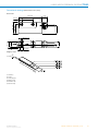
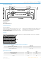
Dimensional drawings (Dimensions in mm (inch))
Read head, male connector
14
5.5
(.22)
10
(.39)
5.3
(.21)
10
–0,1
0
M12 x 1
14 (.55)
61.5 (2.42)
40 (1.57)
8
(.31)
13 (.51)
6.6 (.26)
5.5 (.22)
70 (2.76)
30 (1.18)
23.6 (.93)
Read head, cable
8
(0.31)
6.7
(0.26)
70 (2.76)
40 (1.57)
30 (1.18)
11.2
(0.44)
23.6 (0.93)
~ 18
(0.71)
50 (1.97)
2.5
(0.10)
Ø 5.3
(0.21)
21 (0.83)
14 (0.55)
10–0.1
(0.39)
0
5.3
(0.21)
5.5
(0.22)
5.5
(0.22)
10
(0.39)
1
1 Screen
A
B
C
D
E
F
H
I
J
K
L
M
N
O
P
Q
R
S
T

ENCODERS | SICK8015022/2021-05-27
Subject to change without notice
7
LINEAR ENCODERS TTK70
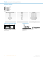
Magnetic tape
3
4
5
6
2
1
≤ 1.526
1 Thickness
2 Length
3 Conveying tape
4 Magnetic tape
5 Substrate tape
6 Adhesive tape
A
B
C
D
E
F
H
I
J
K
L
M
N
O
P
Q
R
S
T

ENCODERS | SICK 8015022/2021-05-27
Subject to change without notice
8
TTK70 LINEAR ENCODERS
PIN and wire assignment
COS +
REFCOS
SIN +
REFSIN
PK
BK
WH
BN
Daten +
Daten -
GND
U
S
GY/YE
GN/VT
BU
RD
PIN Wire colors (cable connection) Signal Explanation
1 Brown REFSIN Process data channel
2 White + SIN Process data channel
3 Black REFCOS Process data channel
4 Pink + COS Process data channel
5 Gray or yellow Data + Parameter channel RS 485
6 Green or purple Data - Parameter channel RS 485
7 Blue GND Ground connection
8 Red U
S
Supply voltage
Screen Housing
Order note for magnetic tape length
5
5
70
1
2
1 Required band length = measurement path + 80 mm
2 Measurement path
Position tolerance
< ± 1°
≤
≤
General tolerances according to DIN ISO 2768-mk
1 Without cover strip
2 With cover strip
A
B
C
D
E
F
H
I
J
K
L
M
N
O
P
Q
R
S
T

ENCODERS | SICK8015022/2021-05-27
Subject to change without notice
9
LINEAR ENCODERS TTK70
A
B
C
D
E
F
H
I
J
K
L
M
N
O
P
Q
R
S
T

MOTOR FEEDBACK SYSTEMS | SICK 8015022/2021-05-27
Subject to change without notice
10
TTK50 LINEAR MOTOR FEEDBACK SYSTEMS
Product description
Precision, speed, dynamics, stiness
and high control accuracy - it is exactly
these properties which play an import-
ant role in high-end applications in drive
technology. The TTK50 linear measure-
ment system has all these properties
and is a very compact motor feedback
system with HIPERFACE
®
interface.
The magnetic principle of operation,
the long measuring length, and the
extremely high resolution open up all
kinds of application possibilities for
absolute position detection with linear
motors. The TTK50 contains the newest
sensor and evaluation technology. The
sensor board aligned to the measuring
plane is equipped with Hall sensors in
two parallel tracks. Their arrangement
corresponds with the division of the
magnetic tape into an incremental and
an absolute component. To calculate
the absolute position values during
operation, the read head initially detects
the absolute starting position when the
linear motor starts. All other actual po-
sitions of the drive are then determined
via the incremental position on the mag-
netic track or the sine/cosine signals.
At a glance
• Absolute, non-contact, wear-free
length measurement system for
linear motors
• Measured lengths of up to 1 m
• Suitable for high traverse speeds of
up to 10 m/s
• Reliable location positioning even in
the event of condensation and con-
tamination of the magnetic tape
• Electronic type label and program-
ming of the position value
• Absolute location positioning, no
reference run
• HIPERFACE
®
interface
• Certied according to SIL2 and PL d
Your benets
• Reference traverse no longer nec-
essary due to absolute measuring
system
• Maintenance-free thanks to non-con-
tact measuring principle
• Simple integration of the system due
to the HIPERFACE
®
interface
• Developed specically for use in
linear direct drives
• Also for use in rough ambient condi-
tions
• Certication allows for easy integra-
tion into a safe drive system
Motor feedback systems
LINEAR MOTOR FEEDBACK SYSTEMS
TTK50
TOP-SPEED MEASUREMENT FOR LINEAR MOTORS
Additional information
Detailed technical data . . . . . . . . . . 11
Ordering information . . . . . . . . . . . . 12
Dimensional drawings . . . . . . . . . . . 13
PIN and wire assignment . . . . . . . . . 14
Order note for magnetic tape length 14
Position tolerance. . . . . . . . . . . . . . . 14
Communication interface . . . . . . . . 15
Technical Description. . . . . . . . . . . . 15
Diagrams . . . . . . . . . . . . . . . . . . . . . . 15
Charactersitics applicable to all per-
missible environmental conditions. 15
Model-specic settings . . . . . . . . . . 15
Overview of supported commands for
HIPERFACE
®
. . . . . . . . . . . . . . . . . . . . .16
Overview of status messages for HIP-
ERFACE
®
. . . . . . . . . . . . . . . . . . . . . . .16
Additional information . . . . . . . . . . . .17
Recommended accessories . . . . . . 19
- www.sick.com/TTK50
For more information, simply enter the link or scan the QR code and get direct access to
technical data, CAD design models, operating instructions, software, application examples, and
much more.
A
B
C
D
E
F
H
I
J
K
L
M
N
O
P
Q
R
S
T

MOTOR FEEDBACK SYSTEMS | SICK8015022/2021-05-27
Subject to change without notice
11
LINEAR MOTOR FEEDBACK SYSTEMS TTK50
Detailed technical data
Features
Items supplied
Magnetic tape not included with delivery
Performance
Measuring step
0.244 µm For interpolation of the sine/cosine signals with, e. g., 12 bits
Measuring length
≤ 940 mm
Resolution
1 µm
Length of period
1 mm
Traversing speed
≤ 10 m/s, up to which the absolute position can be reliably produced
1.3 m/s
Repeatability
< 5 µm
System accuracy
± 10 µm (+20 °C)
Measured value backlash
< 10 µm
Interfaces
Code type
Binary
Available memory area
1,972 Byte (E
2
PROM 2048)
Mechanical data
Dimensions
See dimensional drawing
Weight
Read head 0.06 kg, without cable
Magnetic tape 0.18 kg/m
Magnetic strip length
See ordering information
Read head material
Zinc diecast
Material, magnetic tape
17410 Hard ferrite 9/28 P
Material mounting tape
Stainless steel
Electrical data
Supply voltage
7 V DC ... 12 V DC
Recommended supply voltage
8 V DC
Operating current
≤ 55 mA (without load)
1)
Connection type
Cable, 8-wire, 0.5 m
Cable, 8-wire, 2 m
1)
100 mA approx. during adjustment.
Ambient data
EMC
According to EN 61000-6-2 and EN 61000-6-3
1)
Enclosure rating
IP67, with mating connector inserted (according to IEC 60529)
Operating temperature range
Read head –30 °C ... +80 °C
Magnetic tape –20 °C ... +100 °C
Storage temperature range
1)
According to the listed standards, EMC is guaranteed if the motor feedback system is connected to the central grounding point of the motor controller via a
cable shield and the encoder housing lays over a large area of the motor potential. If other shielding concepts are used, users must perform their own test.
2)
The maximum permitted external eld inuence is reached when the position value deviates from the original value (without external eld inuence) by more
than 5 μm. This value is reached when, at the sensor location, a eld strength of 3 kA/m to 4 kA/m (3.8 mT to 5 mT) occurs in addition to the eld strength of
the magnetic tape.
A
B
C
D
E
F
H
I
J
K
L
M
N
O
P
Q
R
S
T

MOTOR FEEDBACK SYSTEMS | SICK 8015022/2021-05-27
Subject to change without notice
12
TTK50 LINEAR MOTOR FEEDBACK SYSTEMS
Read head –40 °C ... +85 °C, without package
Magnetic tape –30 °C ... +100 °C
Permissible relative humidity
100 %, condensation permitted
Resistance to shocks
30 g, 6 ms (EN 60068-2-27)
Resistance to vibration
20 g, 10 Hz ... 2,000 Hz (EN 60068-2-6)
Temperature coecient magnetic tape
(11 ± 1) µm/K/m
Maximum permitted ambient eld
strength
< 3 kA/m ... 4 kA/m (3.8 mT ... 5 mT), to guarantee compliance with the quoted accuracy
values
2)
Maximum permitted eld strength
< 150 kA/m (< 190 mT), to ensure that the magnetic tape is not permanently damaged
1)
According to the listed standards, EMC is guaranteed if the motor feedback system is connected to the central grounding point of the motor controller via a
cable shield and the encoder housing lays over a large area of the motor potential. If other shielding concepts are used, users must perform their own test.
2)
The maximum permitted external eld inuence is reached when the position value deviates from the original value (without external eld inuence) by more
than 5 μm. This value is reached when, at the sensor location, a eld strength of 3 kA/m to 4 kA/m (3.8 mT to 5 mT) occurs in addition to the eld strength of
the magnetic tape.
Safety-related parameters
Note
The following parameters are only valid for SIL2 certied versions
Safety integrity level
SIL2 (IEC 61508), SILCL2 (EN 62061)
1)
Category
3 (EN ISO 13849)
Maximum demand rate
Continuous (analog signals)
Performance level
PL d (EN ISO 13849)
PFH
D
: Probability of dangerous failure per
hour
2.02 x 10
-8
2)
T
M
(mission time)
20 years (EN ISO 13849)
Safety-related accuracy
± 25 mm, = ± 1/4 pin length
Safety-related measuring step
0.25 mm
1)
For more detailed information on the exact conguration of your machine/unit, please consult your relevant SICK branch oce.
2)
The values displayed apply to a diagnostic degree of coverage of 90%, which must be achieved by the external drive system.
Ordering information
System part Magnetic strip length Connection type Safety system Type Part no.
Magnetic tape 1 m – – MVM-1M0-2MC-MKLB 6049001
Read head –
Cable, 8-wire, 0.5 m
l
TTK50S-HXJ0-K02 1099696
– TTK50-HXJ0-K02 1057791
Cable, 8-wire, 2 m
l
TTK50S-HXQ0-K02 1099698
– TTK50-HXQ0-K02 1057793
A
B
C
D
E
F
H
I
J
K
L
M
N
O
P
Q
R
S
T

MOTOR FEEDBACK SYSTEMS | SICK8015022/2021-05-27
Subject to change without notice
13
LINEAR MOTOR FEEDBACK SYSTEMS TTK50
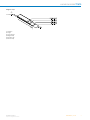
Dimensional drawings (Dimensions in mm (inch))
Read head
25 (0.98)
50
(1.96)
24 (0.94)
17 (0.66)
~ 12
(0.47)
20 (0.78)
14 (0.55)
Ø 3.3 (0.12)
Ø 6 (0.23)
2 (0.07)
6 (0.23)
10
(0.39)
Magnetic tape
3
4
5
6
2
1
≤ 1.526
1 Thickness
2 Length
3 Conveying tape
4 Magnetic tape
5 Substrate tape
6 Adhesive tape
A
B
C
D
E
F
H
I
J
K
L
M
N
O
P
Q
R
S
T

MOTOR FEEDBACK SYSTEMS | SICK 8015022/2021-05-27
Subject to change without notice
14
TTK50 LINEAR MOTOR FEEDBACK SYSTEMS
PIN and wire assignment
COS +
REFCOS
SIN +
REFSIN
PK
BK
WH
BN
Daten +
Daten -
GND
U
S
GY/YE
GN/VT
BU
RD
Wire colors (cable connection) Signal Explanation
Brown REFSIN Process data channel
White + SIN Process data channel
Black REFCOS Process data channel
Pink + COS Process data channel
Gray or yellow Data + Parameter channel RS 485
Green or purple Data - Parameter channel RS 485
Blue GND Ground connection
Red U
S
Supply voltage
Screen Housing
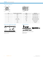
Order note for magnetic tape length
2
1
55
50
1 Required band length = measurement path + 60 mm
2 Measurement path
Position tolerance
0.6 (.02)
0.6
(.02)
≤ 0.3 (.01)
1)
≤ 0.2 (.01)
2)
General tolerances according to DIN ISO 2768-mk
1 Without cover strip
2 With cover strip
A
B
C
D
E
F
H
I
J
K
L
M
N
O
P
Q
R
S
T

MOTOR FEEDBACK SYSTEMS | SICK8015022/2021-05-27
Subject to change without notice
15
LINEAR MOTOR FEEDBACK SYSTEMS TTK50
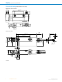
Communication interface
1 Secure data transmission
2 High information content
3 Electronic type label
4 Only 8 cables
5 Bus-compatible parameter channel
6 Process channel in real time
Technical Description
Notes on the diagrams
Access to the process data used for speed control, i.e. to the
sine and cosine signals, is practically always “online”. When
the supply voltage is applied, the speed controller has access
to this information at any time.
Sophisticated technology guarantees stable amplitudes of the
analog signals across all specic environmental conditions,
with a maximum variation of only 20 %.
Diagrams
Signal diagram for clockwise shaft rotation, looking in direction “A” (see dimensional drawing) 1 period = 360° : 64/128/256
Charactersitics applicable to all permissible environmental conditions
Signal Values/unit
Signal peak, peak V
SS
of SIN, COS 0.9 V ... 1.1 V
Signal oset REFSIN, REFCOS 2.2 V ... 2.8 V
Model-specic settings
TTK70 TTK50
Model ID (command 52h) FFh FFh
Free E
2
PROM [bytes] 1,792 1,792
Address 40h 40h
A
B
C
D
E
F
H
I
J
K
L
M
N
O
P
Q
R
S
T

MOTOR FEEDBACK SYSTEMS | SICK 8015022/2021-05-27
Subject to change without notice
16
TTK50 LINEAR MOTOR FEEDBACK SYSTEMS
TTK70 TTK50
Mode_485
1)
E4h E4h
Codes 0 to 3 55h 55h
Counter 0 0
1)
The linear length measuring system supports the following baud rates:
9600, 19200 and 38400.
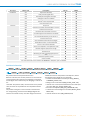
Overview of supported commands for HIPERFACE
®
TTK70 TTK50
Command byte Function Code 0
1)
Comment Comment
42h Read position (5 bits per
sine/cosine period)
31,25 μm 31,25 μm
43h Set position ■
44h Read analog value Channel number 48h Channel number 48h
Temperature [°C]
2)
Temperature [°C]
2)
46h Read counter
47h Increase counter
49h Reset counter ■
4Ah Read data
4Bh Save data
4Ch Determine status of a data
eld
4Dh Create data eld
4Eh Determine available mem-
ory area
4Fh Change access code
50h Read encoder status
52h Read out name plate Encoder type = FFh Encoder type = FFh
53h Encoder reset
55h Allocate encoder address ■
56h Read serial number and
program version
57h Congure serial interface ■
67h Change serial interface
temporary
6Ah Set position with interanal
synchronization
■ See page 17 See page 17
6Bh Sensor adjustment (during
commissioning)
■
1)
The commands thus marked include the parameter ‘Code 0’. Code 0 is a byte inserted into the protocol to provide additional protection of
vital system parameters against accidental overwriting. When the device is supplied, ‘Code 0’ = 55h.
2)
The temperature value
will be reliably formed
approx. 2 s after power on/
reset.
Overview of status messages for HIPERFACE
®
Error type Status code Description TTK70 TTK50
00h The encoder has recognized no error ■ ■
A
B
C
D
E
F
H
I
J
K
L
M
N
O
P
Q
R
S
T

MOTOR FEEDBACK SYSTEMS | SICK8015022/2021-05-27
Subject to change without notice
17
LINEAR MOTOR FEEDBACK SYSTEMS TTK50
Error type Status code Description TTK70 TTK50
Initialization 01h Adjustment data faulty ■ ■
02h Faulty internal angular oset ■ ■
03h Data eld partitioning table destroyed ■ ■
04h Analog limit values not available ■ ■
05h Internal I
2
C bus not operational ■ ■
06h Internal checksum error ■ ■
Protocols 09h Parity error ■ ■
0Ah Checksum of the data transmitted data is incorrect ■ ■
0Bh Unknown command code ■ ■
0Ch Number of data transmitted is incorrect ■ ■
0Dh Command argument transmitted is not allowed ■ ■
Data 0Eh The selected data eld may not be written to ■ ■
0Fh Incorrect access code ■ ■
10h Size of data eld stated cannot be changed ■ ■
11h Word address states, is outside data eld ■ ■
12h Access to non-existent data eld ■ ■
Position 20h Sensor is not adjusted or is in adjustment mode ■ ■
21h Distance magnetic tape/sensor too high ■ ■
23h Positional error ■ ■
Other 1Ch Monitoring the value of analog signals (process
data)
■ ■
1Eh Encoder temperature critical ■ ■
08h Counter overow ■ ■
For more information on the interface see HIPERFACE
®
- description, part no. 8010701
Additional information
address 6Ah Pos_HH Pos_HL Pos_LH Pos_LL Code 0 checksum
address 6Ah
PosNeu_HH PosNeu_HL PosNeu_LH PosNeu_LL
checksum
Set position with internal synchronization 6 Ah
With this command, the encoder position is set such that the
required position value points to the beginning of a period of
the SIN signal. This is achieved by not changing, in contrast to
the
command “Set position” (43h), the lower 5 bits of the position
value, as these are responsible for the interpolation within a
period.
The position value given in the command is transmitted in
the “unsigned long” format with the LSB right-aligned and
saved to non-volatile memory. The value range is between 0 ..
127999 and must be interpreted as a multiple of 1/32mm.
The following events trigger an error message:
• Number of transmitted command bytes wrong (WRONG_
COMMAND_LENGTH, 0Ch)
• Wrong access code entered (ERR_ACCESS_CODE, 0Fh),
• Internal error occurred, which would lead to an invalid posi-
tion value (ERR_INT_ANGLE_OFFSET, 02h),
• Encoder is not adjusted (ERR_NOT_CALIBRATED, 20h),
• Transmitted command argument is invalid (WRONG_ARGU-
MENT, 0Dh),
• Internal checksum error (ERR_CHKSUM, 06h)
A
B
C
D
E
F
H
I
J
K
L
M
N
O
P
Q
R
S
T

MOTOR FEEDBACK SYSTEMS | SICK 8015022/2021-05-27
Subject to change without notice
18
TTK50 LINEAR MOTOR FEEDBACK SYSTEMS
5 LS
B
of the digita
l
absolu
te position
– Sine
– Cosine
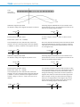
Codication magnetic tape TTK70
The absolute coding of the magnetic tape allows a maximum
measuring range of 4095.999 mm. As the resolution of the
position data is 1/32 mm, the resulting numeric value for the
maximum measuring range is 131072.
00
+131071 +1
+131071 +1
Internal position calculation TTK70
Position value (-3072 .. 00 .. +127999):
To avoid rapid jumps to the maximum value, around the
0 position, the max. measuring range is limited to 4000mm
(= 128000 * 1/32mm). Therefore, in the negative direction
of travel, a range of –96mm (= –3072 * 1/32mm) can be
detected.
Due to the positional calculations performed inside the TTK70,
during commissioning it is necessary to send the command
“6Ah” (Position set with internal synchronisation) at the start
of the magnetic tape.
00
+127999 -3072 -1 +1 +127999 -3072 -1 +1
Codication magnetic tape TTK50
The absolute coding of the magnetic tape allows a max.
measuring range of 1023.999 mm. As the resolution of the
position data is 1/32 mm, the resulting numeric value for the
maximum measuring range is 32768.
00
+32768 +1
+32768 +1
Internal position calculation TTK50
Position value (-768 .. 00 .. +31999):
To avoid rapid jumps to the maximum value, around the
0 position, the max. measuring range is limited to 1000 mm
(= 32000 * 1/32 mm). Therefore, in the negative direction
of travel, a range of –24 mm (= –768 * 1/32 mm) can be
detected.
It is necessary to send the command “6Ah” (Position set with
internal synchronisation) at the start of the magnetic tape due
to the positional calculations performed inside the TTK50,
during commissioning. To avoid that, the sensor produces a
negative value, which the connected controller might not be
able to interpret correctly, the tape is limited to a length of
1000 mm. The magnetization of the magnetic tape is such
that the sensor only sends positive values. Due to this the
maximum measuring range is restricted 940 mm.
00
+31999 -768 -1 +1 +31999 -768 -1 +1
A
B
C
D
E
F
H
I
J
K
L
M
N
O
P
Q
R
S
T

MOTOR FEEDBACK SYSTEMS | SICK8015022/2021-05-27
Subject to change without notice
19
LINEAR MOTOR FEEDBACK SYSTEMS TTK50
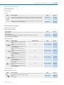
Recommended accessories
Mounting systems
Nuts and screws
Screws
Figure Brief description Type Part no.
Mounting kit for SIL2 applications for safe and easy mounting of the TTK70S; 2x titan
cylinder screws, 2x galvanized steel lock washers, 2x washers, 2x female connectors
BEF-MK-S12 2105618
Mounting kit for SIL2 applications for safe and easy mounting of the TTK50S; 2x coun-
tersunk head screws, 1x mounting plate
BEF-MK-S13 2109583
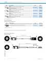
Plug connectors and cables
Plug connectors and cables
Cables (ready to assemble)
Brief description Type Part no.
Head A: cable
Head B: Flying leads
Cable: HIPERFACE
®
, HIPERFACE
®
, PUR, halogen-free, shielded, 4 x 2 x 0.15 mm², 5.3 mm
Signalart: HIPERFACE
®
, HIPERFACE
®
LTG-2708-MW 6028361
Connection cables
Figure Brief description Length of cable Type Part no.
Head A: female connector, M23, 12-pin,
straight
Head B: male connector, M23, 17-pin,
straight
Cable: HIPERFACE
®
, unshielded, 5.6 mm
Signalart: HIPERFACE
®
1 m DSL-2317-G01MJB2 2071328
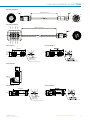
Head A: female connector, JST, 8-pin,
straight
Head B: male connector, M23, 17-pin,
straight
Cable: HIPERFACE
®
, unshielded, 5.6 mm
Signalart: HIPERFACE
®
1 m DSL-2317-G01MJB6 2071327
Head A: female connector, M12, 8-pin,
straight
Head B: male connector, M23, 17-pin,
straight
Cable: HIPERFACE
®
, unshielded, 5.6 mm
Signalart: HIPERFACE
®
1 m DSL-2317-G01MJC1 2071329
Head A: female connector, terminal box,
8-pin, straight
Head B: male connector, M23, 17-pin,
straight
Cable: HIPERFACE
®
, unshielded, 5.6 mm
Signalart: HIPERFACE
®
1 m DSL-2317-G01MJC6 2071330
Dimensional drawings g page 20
Field-attachable connectors
Figure Brief description Type Part no.
Head A: female connector, M12, 8-pin, straight
Head B: -
Cable: shielded
DOS-1208-GA 6028369
A
B
C
D
E
F
H
I
J
K
L
M
N
O
P
Q
R
S
T

MOTOR FEEDBACK SYSTEMS | SICK 8015022/2021-05-27
Subject to change without notice
20
TTK50 LINEAR MOTOR FEEDBACK SYSTEMS
Figure Brief description Type Part no.
Head A: female connector, M12, 8-pin, straight, A-coded
Head B: -
Cable: Incremental, SSI, shielded, CAT5, CAT5e
Signalart: Incremental, SSI
DOS-1208-GA01 6045001
Head A: female connector, M12, 8-pin, angled, A-coded
Head B: -
Cable: Ethernet, shielded, CAT5, CAT5e
Signalart: Ethernet
DOS-1208-WA 6043358
Head A: male connector, M12, 8-pin, straight
Head B: -
Cable: shielded
STE-1208-GA 6028370
Head A: male connector, M12, 8-pin, straight, A-coded
Head B: -
Cable: Incremental, shielded, CAT5, CAT5e
Signalart: Incremental
STE-1208-GA01 6044892
Dimensional drawings g page 20
Further accessories
Programming and conguration tools
Figure Brief description Type Part no.
SVip
®
LAN programming tool for all motor feedback systems PGT-11-S LAN 1057324
Dimensional drawings g page 22
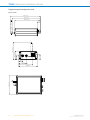
Dimensional drawings for accessories (Dimensions in mm (inch))
Plug connectors and cables
DSL-2317-G01MJB2
11
1
2
3
4
5
6
7
8
9
10
12
13
14
15
16
17
E
1
2
3
4
5
6
7
8
9
12 10
11
Y
1000 ± 15 (39.37)
X
DSL-2317-G01MJB6
11
1
2
3
4
5
7
8
9
10
12
13
14
15
16
17
E
6
Y
1000 ± 15 (39.37)
X
30
+5
(1.18)
81
2 blu
3 red
7 blk
à pnk
á vi
ã yel
ä brn
å wht
A
B
C
D
E
F
H
I
J
K
L
M
N
O
P
Q
R
S
T
Page is loading ...
Page is loading ...
Page is loading ...
Page is loading ...
-
 1
1
-
 2
2
-
 3
3
-
 4
4
-
 5
5
-
 6
6
-
 7
7
-
 8
8
-
 9
9
-
 10
10
-
 11
11
-
 12
12
-
 13
13
-
 14
14
-
 15
15
-
 16
16
-
 17
17
-
 18
18
-
 19
19
-
 20
20
-
 21
21
-
 22
22
-
 23
23
-
 24
24


SICK TTK70/TTK50 Linear motor feedback systems Product information
- Type
- Product information
Ask a question and I''ll find the answer in the document
Finding information in a document is now easier with AI
Related papers
-
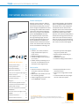
SICK TTK70/TTK50 Motor feedback system linear HIPERFACE® Product information
-
-
-
-
-
-
-
-
-
Other documents
-
Danfoss VLT AutomationDrive FC 301 Installation guide
-
Barco R9801310 Datasheet
-
SCHUNK LDM-ES-0100 Assembly And Operating Manual
-
-
Allen-Bradley PowerFlex 700H Installation guide
-
Kollmorgen AKD2G-S Series Installation guide
-
-
Lika SME54 User manual
-
Kollmorgen S72401 User manual
-
 Rockwell Automation Allen-Bradley VPF-B1001 Installation Instructions Manual
