Page is loading ...

V
V-Serie
V-Series
Drehschieber
Rotary Vane
Edition: 1.12.2009 · BA 159-EN
Original Operating Instructions
V-VCB
V-VCB 20 | 25

2| www.gd-elmorietschle.com © Gardner Denver Schopfheim GmbH, Gardner Denver Deutschland GmbH
Table of contents
Table of contents
1 Foreword . . . . . . . . . . . . . . . . . . . . . . . . . . . . . . . . . . . . . . . . . . . . . . . . . . . . . . . . . . . . . . . . . . . 4
1.1 Principles . . . . . . . . . . . . . . . . . . . . . . . . . . . . . . . . . . . . . . . . . . . . . . . . . . . . . . . . . . . . . . . . . . . 4
1.2 Target group . . . . . . . . . . . . . . . . . . . . . . . . . . . . . . . . . . . . . . . . . . . . . . . . . . . . . . . . . . . . . . . . . 4
1.3 Supplier documentation and accompanying documents . . . . . . . . . . . . . . . . . . . . . . . . . . . . . . 4
1.4 Abbreviations . . . . . . . . . . . . . . . . . . . . . . . . . . . . . . . . . . . . . . . . . . . . . . . . . . . . . . . . . . . . . . . . 4
1.5 Directives, standards, laws . . . . . . . . . . . . . . . . . . . . . . . . . . . . . . . . . . . . . . . . . . . . . . . . . . . . . 4
1.6 Symbols and meaning . . . . . . . . . . . . . . . . . . . . . . . . . . . . . . . . . . . . . . . . . . . . . . . . . . . . . . . . . 5
1.7 Technical terms and meaning . . . . . . . . . . . . . . . . . . . . . . . . . . . . . . . . . . . . . . . . . . . . . . . . . . . 5
1.8 Copyright . . . . . . . . . . . . . . . . . . . . . . . . . . . . . . . . . . . . . . . . . . . . . . . . . . . . . . . . . . . . . . . . . . . 5
2 Safety . . . . . . . . . . . . . . . . . . . . . . . . . . . . . . . . . . . . . . . . . . . . . . . . . . . . . . . . . . . . . . . . . . . . . 6
2.1 Warning instruction markings . . . . . . . . . . . . . . . . . . . . . . . . . . . . . . . . . . . . . . . . . . . . . . . . . . . 6
2.2 General . . . . . . . . . . . . . . . . . . . . . . . . . . . . . . . . . . . . . . . . . . . . . . . . . . . . . . . . . . . . . . . . . . . . . 6
2.3 Designated use . . . . . . . . . . . . . . . . . . . . . . . . . . . . . . . . . . . . . . . . . . . . . . . . . . . . . . . . . . . . . . 7
2.4 Unacceptable operating modes . . . . . . . . . . . . . . . . . . . . . . . . . . . . . . . . . . . . . . . . . . . . . . . . . . 7
2.5 Personal qualifi cations and training . . . . . . . . . . . . . . . . . . . . . . . . . . . . . . . . . . . . . . . . . . . . . . . 8
2.6 Safety-conscious work . . . . . . . . . . . . . . . . . . . . . . . . . . . . . . . . . . . . . . . . . . . . . . . . . . . . . . . . 8
2.7 Safety notes for the operator . . . . . . . . . . . . . . . . . . . . . . . . . . . . . . . . . . . . . . . . . . . . . . . . . . . . 8
2.8 Safety instructions for installing, commissioning and maintenance . . . . . . . . . . . . . . . . . . . . . . 9
2.9 Guarantee conditions . . . . . . . . . . . . . . . . . . . . . . . . . . . . . . . . . . . . . . . . . . . . . . . . . . . . . . . . . . 9
3 Transport, storage and disposal . . . . . . . . . . . . . . . . . . . . . . . . . . . . . . . . . . . . . . . . . . . . . . . . 10
3.1 Transportation . . . . . . . . . . . . . . . . . . . . . . . . . . . . . . . . . . . . . . . . . . . . . . . . . . . . . . . . . . . . . . . 10
3.1.1 Unpack and check the delivery condition . . . . . . . . . . . . . . . . . . . . . . . . . . . . . . . . . . 10
3.1.2 Lifting and transporting . . . . . . . . . . . . . . . . . . . . . . . . . . . . . . . . . . . . . . . . . . . . . . . . . 10
3.2 Storage . . . . . . . . . . . . . . . . . . . . . . . . . . . . . . . . . . . . . . . . . . . . . . . . . . . . . . . . . . . . . . . . . . . . . 11
3.2.1 Ambient conditions for storage . . . . . . . . . . . . . . . . . . . . . . . . . . . . . . . . . . . . . . . . . . 11
3.3 Disposal . . . . . . . . . . . . . . . . . . . . . . . . . . . . . . . . . . . . . . . . . . . . . . . . . . . . . . . . . . . . . . . . . . . . 11
4 Set up and operation . . . . . . . . . . . . . . . . . . . . . . . . . . . . . . . . . . . . . . . . . . . . . . . . . . . . . . . . . 12
4.1 Setup . . . . . . . . . . . . . . . . . . . . . . . . . . . . . . . . . . . . . . . . . . . . . . . . . . . . . . . . . . . . . . . . . . . . . . 12
4.1.1 Data plate . . . . . . . . . . . . . . . . . . . . . . . . . . . . . . . . . . . . . . . . . . . . . . . . . . . . . . . . . . . 13
4.2 Description . . . . . . . . . . . . . . . . . . . . . . . . . . . . . . . . . . . . . . . . . . . . . . . . . . . . . . . . . . . . . . . . . 13
4.3 Areas of application . . . . . . . . . . . . . . . . . . . . . . . . . . . . . . . . . . . . . . . . . . . . . . . . . . . . . . . . . . . 13
5 Installation . . . . . . . . . . . . . . . . . . . . . . . . . . . . . . . . . . . . . . . . . . . . . . . . . . . . . . . . . . . . . . . . . 14
5.1 Preparing for installation . . . . . . . . . . . . . . . . . . . . . . . . . . . . . . . . . . . . . . . . . . . . . . . . . . . . . . . 14
5.2 Installation . . . . . . . . . . . . . . . . . . . . . . . . . . . . . . . . . . . . . . . . . . . . . . . . . . . . . . . . . . . . . . . . . . 14
5.3 Connecting pipes . . . . . . . . . . . . . . . . . . . . . . . . . . . . . . . . . . . . . . . . . . . . . . . . . . . . . . . . . . . . 15
5.4 Filling with lubricating oil . . . . . . . . . . . . . . . . . . . . . . . . . . . . . . . . . . . . . . . . . . . . . . . . . . . . . . . 15
5.5 Connecting the motor . . . . . . . . . . . . . . . . . . . . . . . . . . . . . . . . . . . . . . . . . . . . . . . . . . . . . . . . . 16
6 Commissioning and decommissioning . . . . . . . . . . . . . . . . . . . . . . . . . . . . . . . . . . . . . . . . . . 17
6.1 Commissioning . . . . . . . . . . . . . . . . . . . . . . . . . . . . . . . . . . . . . . . . . . . . . . . . . . . . . . . . . . . . . . 17
6.1.1 Checking the rotation direction. . . . . . . . . . . . . . . . . . . . . . . . . . . . . . . . . . . . . . . . . . . 18
6.2 Decommissioning/ storing . . . . . . . . . . . . . . . . . . . . . . . . . . . . . . . . . . . . . . . . . . . . . . . . . . . . . 18
6.3 Re-commissioning . . . . . . . . . . . . . . . . . . . . . . . . . . . . . . . . . . . . . . . . . . . . . . . . . . . . . . . . . . . 18

3
www.gd-elmorietschle.com © Gardner Denver Schopfheim GmbH, Gardner Denver Deutschland GmbH |
Table of contents
7 Maintenance and repair . . . . . . . . . . . . . . . . . . . . . . . . . . . . . . . . . . . . . . . . . . . . . . . . . . . . . . . 19
7.1 Ensuring operational safety . . . . . . . . . . . . . . . . . . . . . . . . . . . . . . . . . . . . . . . . . . . . . . . . . . . . . 19
7.2 Maintenance work . . . . . . . . . . . . . . . . . . . . . . . . . . . . . . . . . . . . . . . . . . . . . . . . . . . . . . . . . . . . 19
7.2.1 Air fi ltering . . . . . . . . . . . . . . . . . . . . . . . . . . . . . . . . . . . . . . . . . . . . . . . . . . . . . . . . . . . 20
7.2.2 Coupling . . . . . . . . . . . . . . . . . . . . . . . . . . . . . . . . . . . . . . . . . . . . . . . . . . . . . . . . . . . . 21
7.2.3 Lubrication . . . . . . . . . . . . . . . . . . . . . . . . . . . . . . . . . . . . . . . . . . . . . . . . . . . . . . . . . . 22
7.2.4 Oil removal . . . . . . . . . . . . . . . . . . . . . . . . . . . . . . . . . . . . . . . . . . . . . . . . . . . . . . . . . . 23
7.3 Repair/ Service . . . . . . . . . . . . . . . . . . . . . . . . . . . . . . . . . . . . . . . . . . . . . . . . . . . . . . . . . . . . . . . 24
7.4 Spare parts . . . . . . . . . . . . . . . . . . . . . . . . . . . . . . . . . . . . . . . . . . . . . . . . . . . . . . . . . . . . . . . . . . 25
8 Malfunctions: Causes and elimination . . . . . . . . . . . . . . . . . . . . . . . . . . . . . . . . . . . . . . . . . . . 26
9 Technical Data . . . . . . . . . . . . . . . . . . . . . . . . . . . . . . . . . . . . . . . . . . . . . . . . . . . . . . . . . . . . . . 29

4| www.gd-elmorietschle.com © Gardner Denver Schopfheim GmbH, Gardner Denver Deutschland GmbH
Foreword
1 Foreword
1.1 Principles
These operating instructions:
• are a part of the following oil-fl ooded rotary vane
vacuum pumps, V-VCB 20 and V-VCB 25.
• describe how to use them safely and properly in
all life phases.
• must be available where the equipment is used.
1.2 Target group
The target group for these instructions is technically
trained specialists.
1.3 Supplier documentation and accompanying documents
Document Contents No.
Supplier documentation
Operating Instructions BA 159-EN
Declaration of Conformity C 0041-EN
Declaration of harmlessness 7.7025.003.17
Spare parts’ list Spare parts document E 159
Data sheet Technical data and graphs D 159
Info sheet Water vapour compatibility for oil-fl ooded
vacuum pumps I 200
Info sheet Storage guidelines for machines I 150
Manufacturer’s declaration EU Directive 2002/95/EG (RoHS) —
1.4 Abbreviations
Fig. Figure
V-VCB Vacuum pump
m3/h Pumping capacity
mbar (abs.) Final vacuum, operating vacuum
1.5 Directives, standards, laws
See Conformity Declaration

5
www.gd-elmorietschle.com © Gardner Denver Schopfheim GmbH, Gardner Denver Deutschland GmbH |
Foreword
1.6 Symbols and meaning
Symbol Explanation
Condition, pre-requisite
#### Instructions, action
a), b),... Instructions in several steps
Results
[-> 14] Cross reference with page number
Information, note
Safety symbol
Warns of potential risk of injury
Obey all the safety instructions with this symbol in order to avoid injury
and death.
1.7 Technical terms and meaning
Term Explanation
Machines Pump and motor combination ready to be connected
Motor Pump drive motor
Vacuum pump Machine to create a vacuum
Rotary vane Machine’s design or active principle
Pumping capacity Vacuum pump volume fl ow related to the condition in the suction con-
nection
Final pressure (abs.) The maximum vacuum that a pump reaches when the suction opening is
closed. Given as absolute pressure.
Permanent vacuum The vacuum or the suction range at which the pump operates perma-
nently.
The permanent vacuum or intake pressure is ≥ than the fi nal vacuum and
< than the atmospheric pressure.
Noise emission The noise emitted at a specifi c loading given as a fi gure, sound pressure
level dB(A) as per EN ISO 3744..
1.8 Copyright
Passing on or copying this document, using and
providing information on its contents are prohibited
unless expressly permitted.

6| www.gd-elmorietschle.com © Gardner Denver Schopfheim GmbH, Gardner Denver Deutschland GmbH
Safety
2 Safety
The manufacturer is not responsible for damage if
you do not follow all of this documentation.
2.1 Warning instruction markings
Warning Danger level Consequences if not obeyed
DANGER immediately imminent danger Death, severe bodily injury
WARNING possible imminent danger Death, severe bodily injury
CAUTION possible hazardous situation Slight bodily injury
NOTICE possible hazardous situation Material damage
2.2 General
These operating instructions contain basic instruc-
tions for installation, commissioning, maintenance
and inspection work which must be obeyed to en-
sure the safe operation of the machine and prevent
physical and material damage.
The safety instructions in all sections must be taken
into consideration.
The operating instructions must be read by the
responsible technical personnel/ operator before
installing and commissioning and must be fully un-
derstood. The contents of the operating instructions
must always be available on site for the technical
personnel / operator. Instructions fi xed directly onto
the machine must be obeyed and must always re-
main legible. This applies for example to:
• Symbols for connections
• Data and motor data plate
• Instruction and warning plates
The operator is responsible for observing local regu-
lations.

7
www.gd-elmorietschle.com © Gardner Denver Schopfheim GmbH, Gardner Denver Deutschland GmbH |
Safety
2.3 Designated use
The machine must only be operated in such areas
as are described in the operating instructions:
• only operate the machine in a technically perfect
condition
• do not operate the machine when it is only par-
tially assembled
• the machine must only be operated at an ambi-
ent temperature and a suction temperature of
between 12 and 40°C
Please contact us for temperatures outside this
range.
• the machine may convey, compress or extract
the following media:
• Air
The air extracted may contain water vapour
but no water or other liquids. For water va-
pour compatibility see Info I 200
• all non-explosive, non-infl ammable, non-ag-
gressive and non-poisonous dry gases and
gas air mixtures
2.4 Unacceptable operating modes
• extracting, conveying and compressing explo-
sive, infl ammable, aggressive or poisonous me-
dia, e.g. dust as per ATEX zone 20-22, solvents
as well as gaseous oxygen and other oxidants
• extracting, conveying and compressing ex-
plosive, infl ammable, aggressive, oxidative or
poisonous media, e.g. dust as per ATEX zone
20-22, solvents
• using the machine in non-commercial plants if
the necessary precautions and protective meas-
ures have not been taken in the plant
• installing in environments that are at risk of ex-
plosions
• using the machine in areas with ionising radia-
tion
• back pressures on the outlet side of more than
+0,1bars
• modifi cations to the machine and accessories

8| www.gd-elmorietschle.com © Gardner Denver Schopfheim GmbH, Gardner Denver Deutschland GmbH
Safety
2.5 Personal qualifi cations and training
• Ensure that people entrusted with working on
the machine have read and understood these
operating instructions before starting work,
particularly the safety instructions for installation,
commissioning, maintenance and inspection
work.
• Manage the responsibilities, competence and
monitoring of staff
• all work must only be carried out be technical
specialists:
• Installation, commissioning, maintenance
and inspection work
• Working with electricity
• personnel being trained to work on the ma-
chine must be supervised by technical special-
ists only
2.6 Safety-conscious work
The following safety regulations apply in addition
to the safety instructions and intended use listed in
these instructions:
• Accident prevention regulations, safety and op-
erating regulations
• the standards and laws in force
2.7 Safety notes for the operator
• hot parts of the machine must not be accessible
during operation or must be fi tted with a guard
• People must not be endangered by the free
extraction or discharge of pumped media
• Risks arising from electrical energy must be
eliminated.

9
www.gd-elmorietschle.com © Gardner Denver Schopfheim GmbH, Gardner Denver Deutschland GmbH |
Safety
2.8 Safety instructions for installing, commissioning and maintenance
• The operator will ensure that any installation,
commissioning and maintenance work is car-
ried out by authorised, qualifi ed specialists who
have gained suffi cient information by an in-depth
study of the operating instructions.
• Only work on the machine when it is idle and
cannot be switched on again
• Ensure that you follow the procedure for decom-
missioning the machine described in the operat-
ing instructions.
• Fit or start up safety and protective devices
again immediately after fi nishing work.
• Conversion work or modifi cations to the ma-
chine are only permissible with the manufactur-
er’s consent.
• Only use original parts or parts approved by the
manufacturer. The use of other parts may invali-
date liability for any consequences arising.
• Keep unauthorised people away from the ma-
chine
2.9 Guarantee conditions
The manufacturer’s guarantee or warranty will no
longer apply in the following cases:
• Improper use
• Not complying with these instructions
• Operation by insuffi ciently qualifi ed staff
• Using spare parts that have not been approved
by Gardner Denver Schopfheim GmbH
• Unauthorised modifi cations to the machine or
the accessories supplied by Gardner Denver
Schopfheim GmbH

10 | www.gd-elmorietschle.com © Gardner Denver Schopfheim GmbH, Gardner Denver Deutschland GmbH
Transport, storage and disposal
1 2
Fig. 1/1 Lifting and transporting
1 Transport shackle
2 Fixing screw
3 Transport, storage and disposal
3.1 Transportation
3.1.1 Unpack and check the delivery condition
a) Unpack the machine on receipt and check for
transport damage.
b) Notify the manufacturer of transport damage im-
mediately
c) Dispose of the packaging in accordance with the
local regulations in force.
3.1.2 Lifting and transporting
WARNING
Death or limbs crushed as a result of the items
being transported falling or tipping over.
When transporting with the lifting device remem-
ber:
a) Select the lifting device suitable for the total
weight to be transported.
b) Ensure that the machine cannot tip and fall.
c) Do not stop under a suspended load.
d) Put the goods to be conveyed on a horizontal
base.
Lifting device/ Transporting with a crane
WARNING
Bodily injury resulting from improper operation
a) Loads crosswise to the ring level are not per-
mitted.
b) Avoid impact stress.
a) Tighten the fi xing screw (Fig. 1/2) tightly to the
transport shackle (Fig. 1/1) .
b) The machine must be suspended on the trans-
port shackle using the lifting device for lifting
and transporting.

11
www.gd-elmorietschle.com © Gardner Denver Schopfheim GmbH, Gardner Denver Deutschland GmbH |
Transport, storage and disposal
3.2 Storage
NOTICE
Material damage caused by improper storage.
Ensure that the storage area meets the following
conditions:
a) dust free
b) vibration free
3.2.1 Ambient conditions for storage
Ambient conditions Value
Relative humidity 0% to 80%
Storage temperature -10°C to +60°C
For long-term storage (more than 3 months), it is
useful to use a preservation oil rather than operating
oil.
See Info “Machine storage guidelines” I 150
3.3 Disposal
WARNING
Danger from infl ammable, corrosive or poison-
ous substances.
Machines that come into contact with hazard-
ous substances must be decontaminated before
disposal.
When disposing ensure the following:
a) Collect oils and grease separately and dispose
of in accordance with the local regulations in
force.
b) Do not mix solvents, limescale removers and
paint residues
c) Remove components and dispose of them in
accordance with the local regulations in force.
d) Dispose of the machine in accordance with the
national and local regulations in force.
e) Parts subject to wear and tear (marked as such
in the spare parts list) are special waste and
must be disposed of in accordance with the
national and local waste laws.

12 | www.gd-elmorietschle.com © Gardner Denver Schopfheim GmbH, Gardner Denver Deutschland GmbH
Set up and operation
OMN
KI
B
A
HP1
Q
Q
Q
D
F
F
E
E
Q
F
F
E
P
U
4 Set up and operation
4.1 Setup
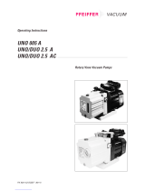
Fig. 2 Vacuum pump V-VCB
A Vacuum connection
B Exhaust air outlet
D Suction fl ange
E Cooling air inlet
F Cooling air outlet
H Oil fi lling point
I Oil sight glass
K Oil discharge point
M Oil recommendation plate
N Data plate
O Rotation direction plate
P Drive motor
P1 Motor data plate
Q hot surfaces > 70°C
U Gas ballast valve (version (07)))

13
www.gd-elmorietschle.com © Gardner Denver Schopfheim GmbH, Gardner Denver Deutschland GmbH |
Bauj./Nr. 09
S1 1,85 / 2,20 kW
Typ VC 75 (20)
0,5 mbar (abs.)
2847746
70 / 84 m³/h
EN 60034
1430 / 1720 min-1
1026502067
3~ Mot.
Set up and operation
6
1
78910
34 52
4.1.1 Data plate
Fig. 3 Data plate (example)
4.2 Description
The V-VCB has a fi ne micro fi lter on the suction side and on the outlet side an oil and oil mist separator to
return the oil to the oil circulation system. A fan between the pump housing and the motor provides intensive
air cooling. The fan is located in a fan cover that guards against it being touched.
An integral non-return valve prevents the evacuated system from being ventilated after the pump has stopped.
If the machine has been idle for more than two minutes the connected pipe should be ventilated to atmospheric
pressure.
A gas ballast valve ((U)➝ version (07)) prevents water vapour condensation from getting into the inside of the
pump when it is sucking in small amounts of steam and the pump is at operating temperature.The pump is
driven by a standard fl anged single-phase or three-phase motor using a coupling.
4.3 Areas of application
These oil-fl ooded rotary vane vacuum pumps V-VCB 20 and V-VCB 25 are suitable h for producing vacu-
ums. The suction power with unrestricted suction is 20 and 22.5 m3/h at 50 Hz. Data sheet D 159.
These types are suitable for the evacuation of closed systems or for a continuous vacuum within the follow-
ing intake pressure ranges:
50 Hz ➝ 2 - 200 mbars (abs.) • 60 Hz➝ 2 - 150 mbars (abs.)
If the machine is operated continuously outside these ranges there is the risk of oil leaking through the outlet
opening. When evacuating closed systems the volume to be evacuated must be no more than 2% of the
nominal pumping capacity of the vacuum pump.
If the unit is switched on more frequently (at regular intervals of about 10 times an hour) or at
higher ambient temperatures and intake temperatures, the excess temperature limit of the motor
winding and the bearings may be exceeded.Please contact the manufacturer should the unit be
used under such conditions.
If it is installed in the open air the unit must be protected from environmental infl uences, (e.g. by a
protective roof).
1 Type/ Size (mechanical version)
2 Year of construction
3 Motor design
4 Serial number
5 Item no.
6 Final pressure (abs.)
7 Pumping capacity 50 Hz/60 Hz
8 Speed 50 Hz/60 Hz
9 Motor output 50 Hz/60 Hz
10 Operating mode

14 | www.gd-elmorietschle.com © Gardner Denver Schopfheim GmbH, Gardner Denver Deutschland GmbH
Installation
5 Installation
5.1 Preparing for installation
Check the following points:
• Machine freely accessible from all sides
• Do not close ventilation grids and holes
• Suffi cient room for installing and removing pipes
and for maintenance work, particularly for install-
ing and dismantling the machine
• No external vibration effects
• Do not suck any hot exhaust air from other ma-
chines into the cooling system.
The oil fi lling pointFig. 2/H), oil sight glassFig. 2/I) and oil outletFig. 2/K) must be easily accessible.
The cooling air inlets (Fig. 2/E) and the cooling air outlets (Fig. 2/F) must be at least 15 cm away
from adjacent walls. Discharged cooling air must not be sucked in again.For maintenance work
there must be a space of at least 30 cm around the machine.
5.2 Installation
NOTICE
The machine may only be operated when it is
set up horizontally.
Material damage resulting from the machine
tipping over and falling.
When installed at more than 1000 m above sea
level a reduction in power is noticeable. In this
case we would ask you to contact us.
Ensure that the foundation complies with the follow-
ing conditions:
• Level and straight
• The bearing surface must be at least the same
size as the machine
• The bearing surface must be able to bear the
weight of the machine
It is possible to install the machine on a fi rm base without anchoring. When installing on a substruc-
ture we recommend fi xing with fl exible buffers

15
www.gd-elmorietschle.com © Gardner Denver Schopfheim GmbH, Gardner Denver Deutschland GmbH |
Installation
5.3 Connecting pipes
NOTICE
Material damage resulting from the forces and
torques of the pipes on the unit being too high.
Only screw pipes in by hand.
The pumping capacity of the vacuum pump
is reduced if the suction pipe is too narrow
and/or too long.
The air vent (Fig. 1/B) must not be closed or
restricted.
Counter pressures on the outlet side are only
permissible up to + 0.1 bars.
Prevent liquids accumulating in the exhaust
line.
a) Vacuum connection (Fig. 2/A).
b) The extracted air can blow freely through the
exhaust air opening (Fig. 2/B).
5.4 Filling with lubricating oil
a) Fill the lubricating oil (for suitable types see the
“Maintenance” section) via the oil fi lling point
(Fig. 2/H) up to the upper edge of the sight glass
(Fig. 2/I).
b) Close the oil fi lling point.

16 | www.gd-elmorietschle.com © Gardner Denver Schopfheim GmbH, Gardner Denver Deutschland GmbH
Installation
5.5 Connecting the motor
DANGER
Danger of death if the electrical installation has
not been done professionally.
The electrical installation must only be done by a
qualifi ed electrician observing EN 60204. The ope-
rating company has to provide the main switch.
a) The motor‘s electrical data is given on the data
plate (Fig. 2/N) or on the motor data plate (Fig. 2/
P1). The motors comply with DIN EN 60034
and are in protection class IP 55 and insulation
class F. The appropriate connection diagram is
located in the motor‘s terminal box (not for the
plug connection version). The motor data must
be compared with the data of the existing mains
network (current type, voltage, network frequen-
cy, permitted current value).
b. Connect the motor via the motor protection
switch (for safety reasons, a motor protection
switch is required and the connecting cable
must be installed via a cable fi tting to provide
strain relief). We recommend using motor pro-
tection switches with delayed switch off, de-
pending on possible excess current. Temporary
excess current can occur when the machine is
started cold..
NOTICE
Power supply
The conditions at the installation location must
match the information on the motor data plate.
Without derating the following is permissible:
• ± 5% Voltage deviation
• ± 2% Frequency deviation

17
www.gd-elmorietschle.com © Gardner Denver Schopfheim GmbH, Gardner Denver Deutschland GmbH |
Commissioning and decommissioning
6 Commissioning and decommissioning
6.1 Commissioning
WARNING
Improper use
May lead to severe or fatal injuries. Therefore be
sure to obey the safety instructions.
CAUTION
Hot surfaces
When the machine is at operating temperature
the surface temperatures on the components (Fig.
1/Q) may go above 70°C.
You must avoid touching the hot surfaces (mar-
ked with warning plates).
CAUTION
Noise emission
The highest noise pressure levels measured as
per EN ISO 3744 are given in Section 9.
When spending a long time in the vicinity of the
running machine use ear protectors to avoid per-
manent damage to your hearing
CAUTION
Oil aerosols in the extracted air
In spite of the air oil removing system separating the
oil mist to a large extent, the extracted air contains
a small residue of oil aerosols. Breathing in these
aerosols all the time could damage your health.
Therefore you must ensure that the installation room
is well ventilated

18 | www.gd-elmorietschle.com © Gardner Denver Schopfheim GmbH, Gardner Denver Deutschland GmbH
Commissioning and decommissioning
6.1.1 Checking the rotation direction
The drive shaft direction of rotation is shown by
the rotation direction arrow (Fig. 2/O) on the mo-
tor fl ange.
a) Start the motor briefl y (max. two seconds) to
check the direction of rotation. When looking at
the motor fan, it must rotate anti-clockwise.
NOTICE
Incorrect direction of rotation
Operating in the wrong direction of rotation leads
to damage to the machine.
Use a phase sequence indicator to check the direc-
tion of rotation (clockwise rotating fi eld).
b) After correcting the direction of rotation if nec-
essary, start the motor again and stop it again
after 2 minutes in order to top missing oil up to
the upper edge of the sight glass (Fig. 2/I). This
topping up at the fi lling point (Fig. 2/H) must be
repeated until all the oil pipes have been fi lled
completely. The fi lling point must not be open
when the pump is running.
6.2 Decommissioning/ storing
Stop the machine
a) Switch the machine off.
b) If available close the cut off device in the suction
and pressure pipe.
c) Disconnect the machine from the electricity
source.
d) Depressurise the machine: Open the pipes
slowly
.
The pressure reduces slowly.
e) Remove the pipes and hoses.
f) Seal the connections for suction and discharge
nozzles with adhesive foil.
see also Section 3.2.1, Page 11
6.3 Re-commissioning
a) Check the condition of the machine (cleanliness,
cabling etc.).
b) Drain the preserving agents.
For installation see Section 5 Page 14
For commissioning see Section 6.1 Page 17

19
www.gd-elmorietschle.com © Gardner Denver Schopfheim GmbH, Gardner Denver Deutschland GmbH |
Maintenance and repair
7 Maintenance and repair
DANGER
Danger of death from touching live parts.
Before maintenance work disconnect the machine
by pressing the main switch or unplugging it and
ensure that it cannot be turned on again.
WARNING
Hot surfaces and equipment
During maintenance work there is the danger of
getting burnt on hot components (Fig. 2/Q) and
by the machine lubricating oil.
Wait for the machine to cool down.
7.1 Ensuring operational safety
Regular maintenance work must be carried out in order to ensure operational safety.
Maintenance intervals also depend on the operational demands on the machine.
With any work observe the safety instructions described in Section 2.8 “Safety notes for installation, com-
missioning and maintenance”.
The whole unit should always be kept in a clean condition.
7.2 Maintenance work
Interval Maintenance to be carried out Section
monthly Check the pipes and screws for leaks and to ensure they are
seated properly and if necessary seal again or tighten up.
—
monthly Check the terminal box and cable inlet holes for leaks and if
necessary re-seal.
—
monthly Clean the ventilation slots on the machine and the motor
cooling ribs.
—
depending on how dirty the
discharged medium is
Clean intake air fi lter 7.2.1
at least once a year Check for coupling wear 7.2.2
daily Check the oil level 7.2.3
500 - 2000 h Change the oil
2000 hrs Change the oil separator element 7.2.4

20 | www.gd-elmorietschle.com © Gardner Denver Schopfheim GmbH, Gardner Denver Deutschland GmbH
Maintenance and repair
f1
hs1
D
s2
7.2.1 Air fi ltering
NOTICE
Insuffi cient maintenance on the air fi lter
The power of the machine lessens and damage may
occur to the machine.
The micro fi lter (Fig. 4/f1) must be cleaned by rinsing
out or purging or replaced more or less often de-
pending on how dirty the discharged medium is.
Also check the non-return valve (Fig. 4/h) for con-
tamination.
Remove the fi lter housing (Fig. 4/D) after undoing
the screws (Fig. 4/s1). Remove the non-return valve
(Fig. 4/h) from the suction fl ange after undoing the
screws (Fig. 4/s2).
Re-assemble in reverse order.
Fig. 4 Air fi ltering
D Suction fl ange
h Non-return valve
f1 Micro fi lter
s1 Screws
s2 Screws
/