
Get technical data,
instruction manuals,
service kits
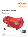
Instruction Manual
R5
Rotary Vane Vacuum Pumps
RB 0021 C Oxygen
with Operating Fluid YLC 250 B
0870149021/A0002_en / Original instructions / Modifications reserved 07/07/2021

Table of Contents
Preface . . . . . . . . . . . . . . . . . . . . . . . . . . . . . . . 2
Technical Data . . . . . . . . . . . . . . . . . . . . . . . . . . . 2
Product Description. . . . . . . . . . . . . . . . . . . . . . . . . 3
Use . . . . . . . . . . . . . . . . . . . . . . . . . . . . . . . . 3
Principle of Operation . . . . . . . . . . . . . . . . . . . . . . 3
Operating Fluid Circulation . . . . . . . . . . . . . . . . . . . . 3
Cooling . . . . . . . . . . . . . . . . . . . . . . . . . . . . . . 4
Start Controls. . . . . . . . . . . . . . . . . . . . . . . . . . . 4
Safety . . . . . . . . . . . . . . . . . . . . . . . . . . . . . . . . 4
Intended Use . . . . . . . . . . . . . . . . . . . . . . . . . . . 4
Safety Notes . . . . . . . . . . . . . . . . . . . . . . . . . . . 4
Emission of Operating Fluid Mist . . . . . . . . . . . . . . . . . 4
Noise Emission . . . . . . . . . . . . . . . . . . . . . . . . . . 4
Transport . . . . . . . . . . . . . . . . . . . . . . . . . . . . . . 5
Transport in Packaging . . . . . . . . . . . . . . . . . . . . . . 5
Transport without Packaging . . . . . . . . . . . . . . . . . . . 5
Storage . . . . . . . . . . . . . . . . . . . . . . . . . . . . . . . 5
Short-term Storage . . . . . . . . . . . . . . . . . . . . . . . . 5
Conservation . . . . . . . . . . . . . . . . . . . . . . . . . . . 5
Installation and Commissioning . . . . . . . . . . . . . . . . . . 5
Installation Prerequisites . . . . . . . . . . . . . . . . . . . . . 5
Mounting Position and Space . . . . . . . . . . . . . . . . . 5
Suction Connection . . . . . . . . . . . . . . . . . . . . . . 6
Gas Discharge . . . . . . . . . . . . . . . . . . . . . . . . . 6
Electrical Connection / Controls . . . . . . . . . . . . . . . . 6
Installation . . . . . . . . . . . . . . . . . . . . . . . . . . . . 7
Mounting . . . . . . . . . . . . . . . . . . . . . . . . . . . 7
Connecting Electrically . . . . . . . . . . . . . . . . . . . . . 7
Connection Scheme Alternating Current Motor . . . . . . . 7
Connection Scheme Three-Phase Motor. . . . . . . . . . . 7
Connecting Lines/Pipes . . . . . . . . . . . . . . . . . . . . 7
Checking the Operating Fluid Level . . . . . . . . . . . . . . 8
Recording of Operational Parameters . . . . . . . . . . . . . 8
Operation Notes . . . . . . . . . . . . . . . . . . . . . . . . . 8
Use . . . . . . . . . . . . . . . . . . . . . . . . . . . . . . 8
Operating Fluid Return. . . . . . . . . . . . . . . . . . . . . 9
Maintenance . . . . . . . . . . . . . . . . . . . . . . . . . . . . 9
Maintenance Schedule . . . . . . . . . . . . . . . . . . . . . . 9
Weekly: . . . . . . . . . . . . . . . . . . . . . . . . . . . 9
Monthly: . . . . . . . . . . . . . . . . . . . . . . . . . . 9
Every Year:. . . . . . . . . . . . . . . . . . . . . . . . . 10
Every 16000 Operating Hours, At the Latest after 4 Years:. 10
Checking the Operating Fluid . . . . . . . . . . . . . . . . . . 10
Checking the Level . . . . . . . . . . . . . . . . . . . . . . 10
Topping up Operating Fluid . . . . . . . . . . . . . . . . . 10
Checking the Colour of the Operating Fluid . . . . . . . . . 10
Operating Fluid Life . . . . . . . . . . . . . . . . . . . . . . . 10
Operating Fluid Change. . . . . . . . . . . . . . . . . . . . . 10
Draining Used Operating Fluid . . . . . . . . . . . . . . . . 11
Filling in Fresh Operating Fluid . . . . . . . . . . . . . . . . 11
Exhaust Filter . . . . . . . . . . . . . . . . . . . . . . . . . . 11
Checks during Operation . . . . . . . . . . . . . . . . . . . 11
Assessment . . . . . . . . . . . . . . . . . . . . . . . . . . 11
Change of the Exhaust Filter . . . . . . . . . . . . . . . . . 11
Removing the Exhaust Filter . . . . . . . . . . . . . . . . 11
Inserting the Exhaust Filter . . . . . . . . . . . . . . . . . 11
Overhaul . . . . . . . . . . . . . . . . . . . . . . . . . . . . . 12
Removal from Service . . . . . . . . . . . . . . . . . . . . . . . 12
Temporary Removal from Service . . . . . . . . . . . . . . . . 12
Recommissioning . . . . . . . . . . . . . . . . . . . . . . . . 12
Dismantling and Disposal . . . . . . . . . . . . . . . . . . . . 12
Troubleshooting . . . . . . . . . . . . . . . . . . . . . . . . . . 13
Spare Parts Kits . . . . . . . . . . . . . . . . . . . . . . . . . . 17
Operating Fluid . . . . . . . . . . . . . . . . . . . . . . . . . . 17
EU-Declaration of Conformity . . . . . . . . . . . . . . . . . . . 18
Busch – All over the World in Industry . . . . . . . . . . . . . . 20
RB 0021 C Oxygen with Operating Fluid YLC 250 B Preface
0870149021 / 110628 page 2
Preface
Congratulations on your purchase of the Busch vacuum pump. With
watchful observation of the field’s requirements, innovation and steady
development Busch delivers modern vacuum and pressure solutions
worldwide.
These operating instructions contain information for
–product description,
–safety,
–transport,
–storage,
–installation and commissioning,
–maintenance,
–overhaul,
–troubleshooting and
–spare parts
of the vacuum pump.
For the purpose of these instructions, “handling” the vacuum pump
means the transport, storage, installation, commissioning, influence on
operating conditions, maintenance, troubleshooting and overhaul of
the vacuum pump.
Prior to handling the vacuum pump these operating instructions shall
be read and understood. If anything remains to be clarified please
contact your Busch representative!
Keep these operating instructions and, if applicable, other pertinent
operating instructions available on site.
Technical Data
Nominal suction capacity
(50Hz/60Hz) m³/h 20 / 24
Ultimate pressure hPa (=mbar)
abs. RB 0021 C:
1.0 / 2.0
Motor nominal rating
(50Hz/60Hz) kW see nameplate
Motor nominal speed
(50Hz/60Hz) min–1 3000 / 3600
Sound pressure level
(EN ISO 2151) (50Hz/60Hz) dB (A) 61 / 66
Ambient temperature range °C 12 ... 40
Ambient pressure Atmospheric
pressure
Operating fluid quantity l 0.45
Operating fluid filled ex-works YLC 250 B
Weight approx. (50Hz/60Hz) kg ~20
UK-Declaration of Conformity . . . . . . . . . . . . . . . . . . . 19

Product Description
Use
The vacuum pump is intended for
–the suction
of
–air and other dry, non-aggressive, non-toxic and non-explosive
gases with increased oxygen content (volume content greater than
21 percent)
Conveying media with a lower or higher density than air leads to an in-
creased thermal and/or mechanical load on the vacuum pump and is
permissible only after prior consultation with Busch.
Max. allowed temperature of the inlet gas: 40 °C
The gas shall be free from vapours that would condensate under the
temperature and pressure conditions inside the vacuum pump.
The vacuum pump is intended for the placement in a non-potentially
explosive environment.
Version with oil return line to the B-cover (RB 0021 C, 2 mbar):
Version with oil return line to the suction connection (RC 0021 C):
The vacuum pump is thermally suitable for continuous operation
(100 percent duty).
Version with oil return valve (RB 0021 C, 1 mbar):
The vacuum pump is thermally suitable for continuous operation (ob-
serve the notes with regard to the operating fluid recirculation:
page 3: Operating Fluid Circulation; page 9: Operating Fluid
Return).
The vacuum pump is ultimate pressure proof.
WARNING_ad
Organic matter and oxygen constitute potentially explosive mix-
tures.
Imminent risk of explosion!
Only special operating fluids, no mineral nor synthetic oils nor
greases are allowed for lubrication of the vacuum pump!
If there is a suspicion that the operating fluid is contaminated with
organic material, is must be changed.
If there is a suspicion that the vacuum pump is contaminated with
organic material, the vacuum pump must removed from service
and cleaned by specialists (Busch service).
Principle of Operation
The vacuum pump works on the rotating vane principle.
A circular rotor is positioned centrically on the shaft of the vacuum
pump. The shaft of the vacuum pump is driven by the drive motor
shaft by means of a flexible coupling.
The rotor rotates in an also circular, fixed cylinder, the centreline of
which is offset from the centreline of the rotor such that the rotor and
the inner wall of the cylinder almost touch along a line. Vanes, sliding
in slots in the rotor, separate the space between the rotor and the cyl-
inder into chambers. At any time gas is sucked in and at almost any
time ejected. Therefore the vacuum pump works almost pulsation free.
In order to avoid the suction of solids, the vacuum pump is equipped
with a screen in the suction connection.
In order to avoid reverse rotation after switching off, the vacuum
pump is equipped with a non-return valve.
Note: This valve shall not be used as a non-return valve or shut-off
valve to the vacuum system and is no reliable means to prevent suction
of operating fluid into the vacuum system while the vacuum pump is
shut down.
Operating Fluid Circulation
The vacuum pump requires operating fluid to seal the gaps, to lubri-
cate the vanes and to carry away compression heat.
The operating fluid reservoir is located on the pressure side of the
vacuum pump (i.e. high pressure) at the bottom of the bottom cham-
ber of the oil separator (g).
Product Description
RB 0021 C Oxygen with Operating Fluid YLC 250 B
0870149021/A0002 page 3
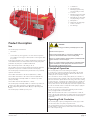
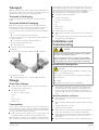
a b c d e f g h i j
a Terminal box
b Directional arrow
c Oil fill plug (position may
vary depending on order)
d Lead seal
e Oil drain plug (position may
vary depending on order)
f Oil sight glass (position may
vary depending on order)
g Oil separator
h Nameplate, vacuum pump
I Suction connection
j Gas discharge

The feed openings are located on the suction side of the vacuum pump
(i.e. low pressure).
Forced by the pressure difference between pressure side and suction
side operating fluid is being drawn from the oil separator (g) through
the oil supply lines and injected on the suction side.
Together with the sucked gas the injected operating fluid gets con-
veyed through the vacuum pump and ejected into the oil separator (g)
as operating fluid mist. Operating fluid that separates before the ex-
haust filter accumulates at the bottom of the bottom chamber of the
oil separator (g).
Operating fluid that is separated by the exhaust filter accumulates at
the bottom of the upper chamber of the oil separator (g).
The flow resistance of the exhaust filters causes the inside of the ex-
haust filters (which is connected to the bottom chamber of the oil sep-
arator) to be on a higher pressure level than the outside of the exhaust
filters (i.e. the upper chamber of the oil separator). Because of the
higher pressure in the bottom chamber it is not possible to let operat-
ing fluid that drips off the exhaust filters simply flow down to the bot-
tom chamber.
Version with oil return line to the suction connection (RC 0021 C):
Therefore the operating fluid that accumulates in the upper chamber is
sucked through the oil return line right to the suction connection.
Version with oil return line to the B-cover (RB 0021 C, 2 mbar):
Therefore the operating fluid that accumulates in the upper chamber is
sucked through the oil return line right to the cylinder chamber.
Version with oil return valve (RB 0021 C, 1 mbar):
At continuous operation this would cause the entire supply of operat-
ing fluid to accumulate at the bottom of the upper chamber, expel op-
erating fluid droplets through the gas discharge/pressure connection
and let the vacuum pump run dry. Therefore the vacuum pump must
be shut down at the latest after 2 hours of continuous operation, de-
pending on the operating conditions even after a shorter period, for at
least approx. 15 minutes ( page 8: Operation Notes). After turning
off the vacuum pump the pressure difference between the inside and
the outside of the exhaust filter(s) collapses, hence the two chambers
of the oil separator assume an equal pressure level, the oil return valve
between the two chambers opens and the accumulated operating fluid
in the upper chamber can run down to the bottom chamber.
Due to the operating fluids property to attach to water vapour, con-
veying humid gas mixtures can cause an increased discharge of operat-
ing fluid. This circumstance does not constitute a deficiency of the
vacuum pump. If the loss of operating fluid caused by the humidity is
too high, either take measures to dehumidify the aspirated gas up-
stream or install a fine mist separator downstream.
Cooling
The vacuum pump is cooled by
–radiation of heat from the surface of the vacuum pump incl. oil
separator (g)
–the air flow from the fan wheel of the drive motor
–the process gas
Start Controls
The vacuum pump comes without start controls. The control of the
vacuum pump is to be provided in the course of installation.
Safety
Intended Use
Definition: For the purpose of these instructions, “handling” the
vacuum pump means the transport, storage, installation, commission-
ing, influence on operating conditions, maintenance, troubleshooting
and overhaul of the vacuum pump.
The vacuum pump is intended for industrial use. It shall be handled
only by qualified personnel.
The allowed media and operational limits ( page 3: Product De-
scription) and the installation prerequisites ( page 5: Installation
Prerequisites) of the vacuum pump shall be observed both by the
manufacturer of the machinery into which the vacuum pump is to be
incorporated and by the operator.
The maintenance instructions shall be observed.
Prior to handling the vacuum pump these installation and operating
instructions shall be read and understood. If anything remains to be
clarified please contact your Busch representative!
Safety Notes
The vacuum pump has been designed and manufactured according to
state-of-the-art methods. Nevertheless, residual risks may remain.
These operating instructions highlight potential hazards where appro-
priate. Safety notes are tagged with one of the keywords DANGER,
WARNING and CAUTION as follows:
DANGER_a
Disregard of this safety note will always lead to accidents with fa-
tal or serious injuries.
WARNING_a
Disregard of this safety note may lead to accidents with fatal or se-
rious injuries.
CAUTION_a
Disregard of this safety note may lead to accidents with minor inju-
ries or property damage.
Emission of Operating Fluid Mist
The operating fluid in the process gas is separated to the greatest pos-
sible extent, but not perfectly.
CAUTION_a
The gas conveyed by the vacuum pump contains remainders of op-
erating fluid.
Aspiration of process gas over extended periods can be harmful.
The room into which the process gas is discharged must be suffi-
ciently vented.
Noise Emission
For the sound pressure level in free field according to EN ISO 2151
page 2: Technical Data.
Safety
page 4
RB 0021 C Oxygen with Operating Fluid YLC 250 B
0870149021/A0002

Transport
Note: The vacuum pump is delivered with operating fluid filled in. Al-
ways transport and store the vacuum pump in upright position. Do not
put the vacuum pump on its side nor put it upside down.
Transport in Packaging
Packed on a pallet the vacuum pump is to be transported with a
forklift.
Transport without Packaging
Note: The vacuum pump is delivered with operating fluid filled in.
When lifting the vacuum pump keep it as horizontal as possible in or-
der to minimise the ingress of operating fluid into the cylinder.
In case the vacuum pump is packed in a cardboard box with inflated
cushions:
Remove the inflated cushions from the box
In case the vacuum pump is in a cardboard box cushioned with rolled
corrugated cardboard:
Remove the corrugated cardboard from the box
In case the vacuum pump is laid in foam:
Remove the foam
Grasp the vacuum pump with both hands
Alternatively:
Loop a belt/rope around the coupling lantern ( illustration)
In case lifting gear is used:
Attach the lifting gear to a crane hook with safety latch
Storage
Short-term Storage
Make sure that the suction connection and the gas discharge are
closed (leave the provided plugs in)
Store the vacuum pump
–if possible in original packaging,
–indoors,
–dry,
–dust free and
–vibration free
Conservation
In case of adverse ambient conditions (e.g. aggressive atmosphere, fre-
quent temperature changes) conserve the vacuum pump immediately.
In case of favourable ambient conditions conserve the vacuum pump if
a storage of more than 3 months is scheduled.
Make sure that all ports are firmly closed; seal all ports that are not
sealed with PTFE-tape, gaskets or o-rings with adhesive tape
Note: VCI stands for “volatile corrosion inhibitor”. VCI-products (film,
paper, cardboard, foam) evaporate a substance that condenses in mo-
lecular thickness on the packed good and by its electro-chemical prop-
erties effectively suppresses corrosion on metallic surfaces. However,
VCI-products may attack the surfaces of plastics and elastomers. Seek
advice from your local packaging dealer! Busch uses CORTEC
VCI 126 R film for the overseas packaging of large equipment.
Wrap the vacuum pump in VCI film
Store the vacuum pump
–if possible in original packing,
–indoors,
–dry,
–dust free and
–vibration free.
For commissioning after conservation:
Make sure that all remains of adhesive tape are removed from the
ports
Commission the vacuum pump as described in the chapter Installa-
tion and Commissioning ( page 5)
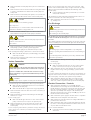
Installation and
Commissioning
WARNING_ad
Installation and commissioning must only be performed by profes-
sionals who are informed about the applicable safety regulations
and trained in the handling of oxygen.
The German accident prevention regulation Oxygen, BGR 500
chapter 2.32 (BGV B7) or the corresponding national accident pre-
vention regulation resp. must be complied with unconditionally.
Installation Prerequisites
CAUTION_a
In case of non-compliance with the installation prerequisites, partic-
ularly in case of insufficient cooling:
Risk of damage or destruction of the vacuum pump and adjoining
plant components!
Risk of injury!
The installation prerequisites must be complied with.
Make sure that the integration of the vacuum pump is carried out
such that the essential safety requirements of the Machine Direc-
tive 2006/42/EC are complied with (in the responsibility of the
de-signer of the machinery into which the vacuum pump is to be
incorporated; page 18: note in the EU-Declaration of Confor-
mity)
Mounting Position and Space
Make sure that the environment of the vacuum pump is not po-
tentially explosive
Make sure that the following ambient conditions will be complied
with:
–ambient temperature: 12 ... 40 °C
–ambient pressure: atmospheric
Make sure that the environmental conditions comply with the pro-
tection class of the drive motor (according to the nameplate)
Make sure that the vacuum pump can neither inadvertently nor in-
tentionally be stepped on and cannot be used as a support for
heavy objects
Make sure that the vacuum pump cannot be hit by falling objects
Transport
page 5
RB 0021 C Oxygen with Operating Fluid YLC 250 B
0870149021/A0002

Make sure that the vacuum pump will be placed or mounted hori-
zontally
Make sure that in order to warrant a sufficient cooling there will be
a clearance of minimum 20 cm between the vacuum pump and
nearby walls
Make sure that no heat sensitive parts (plastics, wood, cardboard,
paper, electronics) will touch the surface of the vacuum pump
CAUTION_ad
The vacuum pump is not absolutely gas tight.
Risk of explosion!
The installation space or location must be vented such that no im-
permissible accumulation of oxygen will occur.
Make sure that the installation space or location is vented such
that a sufficient cooling of the vacuum pump is warranted
CAUTION_ac
During operation the surface of the vacuum pump may reach tem-
peratures of more than 70 °C.
Risk of burns!
Make sure that the vacuum pump will not be touched inadver-
tently during operation, provide a guard if appropriate
Make sure that the sight glass (f) will remain easily accessible
If the operating fluid change is planned to be carried out on location:
Make sure that the drain port (e) and the filling port (c) will re-
main easily accessible
Make sure that enough space will remain for the removal and the
reinsertion of the exhaust filter
Suction Connection
WARNING_ad
Any contamination of the vacuum pump with foreign material, par-
ticularly with organic material leads to imminent risk of explosion.
By means of suitable filters it must be made sure that no foreign
material, particularly no organic material will find its way into the
vacuum pump.
CAUTION_a
Intruding foreign objects or liquids can destroy the vacuum pump.
In case the inlet gas can contain dust or other foreign solid particles:
Make sure that a suitable filter (5 micron or less) is installed
upstream the vacuum pump
Make sure that the filter is approved for oxygen applications
Make sure that the suction line fits to the suction connection (i) of
the vacuum pump
Make sure that the gas will be sucked through a vacuum-tight
flexible hose or a pipe
In case of using a pipe:
Make sure that the pipe will cause no stress on the vacuum
pump’s connection, if necessary use an expansion joint
Make sure that the line size of the suction line over the entire
length is at least as large as the suction connection (i) of the
vacuum pump
In case of very long suction lines it is prudent to use larger line sizes in
order to avoid a loss of efficiency. Seek advice from your Busch
representative!
If two or more vacuum pumps work on the same suction line, if the
volume of the vacuum system is large enough to suck back operating
fluid or if the vacuum shall be maintained after switching off the
vacuum pump:
Provide a manual or automatic operated valve (= non-return
valve) in the suction line
(the standard non-return valve that is installed inside the suction con-
nection is not meant to be used for this purpose!)
Make sure that the suction line does not contain foreign objects,
e.g. welding scales
Gas Discharge
CAUTION_a
Prior to starting up it must be made sure that the plug screws are re-
moved from gas discharge.
Risk of damage to the vacuum pump!
The discharged gas must flow without obstruction. It is not permitted
to shut off or throttle the discharge line or to use it as a pressurised
air source.
The following guidelines for the discharge line do not apply, if the aspi-
rated air is discharged to the environment right at the vacuum pump.
CAUTION_a
The discharged gas contains small quantities of operating fluid.
Staying in operating fluid contaminated air bears a risk of damage to
health.
If air is discharged into rooms where persons stay, sufficient ventila-
tion must be provided for.
Make sure that the discharge line fits to the gas discharge (j) of the
vacuum pump
In case of using a pipe:
Make sure that the pipe will cause no stress on the vacuum
pump’s connection, if necessary use an expansion joint
Make sure that the line size of the discharge line over the entire
length is at least as large as the gas discharge (j) of the vacuum
pump
In case the length of the discharge line exceeds 2 m it is prudent to use
larger line sizes in order to avoid a loss of efficiency and an overload of
the vacuum pump. Seek advice from your Busch representative!
Make sure that the discharge line either slopes away from the
vacuum pump or provide a liquid separator or a drip leg with a
drain cock, so that no liquids can back up into the vacuum pump
Electrical Connection / Controls
Make sure that the stipulations acc. to the EMC-Directive
2004/108/EC and Low-Voltage-Directive 2006/95/EC as well as
the EN-standards, electrical and occupational safety directives and
the local or national regulations, respectively, are complied with
(this is the responsibility of the designer of the machinery into
which the vacuum pump is to be incorporated; page 18: note in
the EU-Declaration of Conformity).
Make sure that the power supply for the drive motor is compatible
with the data on the nameplate of the drive motor
Make sure that an overload protection according to EN 60204-1 is
provided for the drive motor
Make sure that the drive of the vacuum pump will not be affected
by electric or electromagnetic disturbance from the mains; if neces-
sary seek advice from the Busch service
In case of mobile installation:
Provide the electrical connection with grommets that serve as
strain-relief
Installation and Commissioning
page 6
RB 0021 C Oxygen with Operating Fluid YLC 250 B
0870149021/A0002

Installation
Mounting
Make sure that the installation prerequisites ( page 5) are com-
plied with
Set down or mount the vacuum pump at its location
CAUTION_a
Starting the vacuum pump with excessive quantities of operating
fluid in the cylinder will immediately break the vanes and ruin the
vacuum pump.
Remove the hood around the fan wheel of the drive motor
Slowly rotate the fan wheel by hand in intended direction of rota-
tion (see stuck on or cast arrow (b)), so that excess operating fluid,
that made its way into the cylinder during transportation, is con-
veyed into the oil separator
Mount the hood around the fan wheel of the drive motor
Connecting Electrically
WARNING_ab
Risk of electrical shock, risk of damage to equipment.
Electrical installation work must only be executed by qualified per-
sonnel that knows and observes the following regulations:
- IEC 364 or CENELEC HD 384 or DIN VDE 0100, respectively,
- IEC-Report 664 or DIN VDE 0110,
- BGV A2 (VBG 4) or corresponding national accident prevention
regulation.
CAUTION_a
The connection schemes given below are typical. Depending on the
specific order or for certain markets deviating connection schemes
may apply.
Risk of damage to the drive motor!
The inside of the terminal box shall be checked for drive motor con-
nection instructions/schemes.
Electrically connect the drive motor
Connect the protective earth conductor
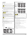
Connection Scheme Alternating Current Motor
Explanation of colour coding:
BK = black
BN = brown
BU = blue
GN = green
RD = red
WH = white
YE = yellow
Connection Scheme Three-Phase Motor
Delta connection (low voltage):
Star connection (high voltage):
CAUTION_ad
Operation in the wrong direction of rotation can destroy the
vacuum pump in short time.
Risk of explosion!
Prior to starting-up it must be made sure that the vacuum pump is
operated in the proper direction (clockwise rotating field).
Version with three-phase motor:
Determine the intended direction of rotation with the arrow
(b) (stuck on or cast)
“Bump” the drive motor
Watch the fan wheel of the drive motor and determine the di-
rection of rotation just before the fan wheel stops
If the rotation must be changed:
Switch any two of the drive motor wires (three-phase motor)
Connecting Lines/Pipes
In case the suction line is equipped with a shut-off valve:
Connect the suction line
Connect the discharge line
Installation without discharge line:
Make sure that the gas discharge (j) is open
Make sure that all provided covers, guards, hoods etc. are
mounted
Make sure that cooling air inlets and outlets are not covered or ob-
structed and that the cooling air flow is not affected adversely in
any other way
Installation and Commissioning
page 7
W2
U1
L1
N
V1
U2
W1
V2
aux
main
BK
BK RD
RD
BN BU
230V
50 Hz
RB 0021 C Oxygen with Operating Fluid YLC 250 B
0870149021/A0002

Checking the Operating Fluid Level
WARNING_ad
The operating fluid is inert and does not contribute to the genera-
tion of potentially explosive gas mixtures.
Any contamination with organic matter leads to an imminent risk
of explosion!
In order to prevent wrong material from being filled in, the vacuum
pump is equipped with one or more lead seals.
Removal or placement of lead seals or work that require the re-
moval of lead seals must only be carried out by specially author-
ised and trained personnel.
Note: Starting the vacuum pump with cold operating fluid is made eas-
ier when at this very moment the suction line is neither closed nor cov-
ered with a rubber mat.
Switch on the vacuum pump
In case the suction line is equipped with a shut-off valve:
Close the shut-off valve
In case the suction line is not equipped with a shut-off valve:
Cover the suction connection (i) with a piece of rubber mat
Let the vacuum pump run for a few minutes
Shut down the vacuum pump and wait a few minutes
Check that the level is between the MIN and the MAX-markings of
the sight glass (f)
In case the level has dropped below the MIN-marking:
WARNING_ad
The vacuum pump must only be operated with the operating fluid
that has been approved by the German Federal Institute for Mate-
rials Research and Testing (Bundesanstalt für Materialforschung
und -prüfung (BAM)) and released for service with this vacuum
pump.
Use of other operating fluids voids the vacuum pump’s approval
for service.
Top-up operating fluid acc. to the table Operating Fluid
( page 17)
In case the suction line is equipped with a shut-off valve:
Open the shut-off valve
In case the suction line is not equipped with a shut-off valve:
Remove the piece of rubber mat and connect the suction line
Make sure that the lead seals are applied
Recording of Operational Parameters
As soon as the vacuum pump is operated under normal operating
conditions:
Measure the drive motor current and record it as reference for fu-
ture maintenance and troubleshooting work
Operation Notes
Use
WARNING_ad
The vacuum pump is designed for operation under the conditions
described below.
In case of disregard risk of explosion!
The vacuum pump must only be operated under the conditions de-
scribed below.
WARNING_ad
Operating a faulty vacuum pump puts the explosion safety at risk.
Risk of explosion!
The vacuum pump must only be operated in faultless condition.
A faulty vacuum pump must immediately be removed from service.
The vacuum pump is intended for
–the suction
of
–air and other dry, non-aggressive, non-toxic and non-explosive
gases with increased oxygen content (volume content greater than
21 percent)
Conveying media with a lower or higher density than air leads to an in-
creased thermal and/or mechanical load on the vacuum pump and is
permissible only after prior consultation with Busch.
Max. allowed temperature of the inlet gas: 40 °C
The gas shall be free from vapours that would condensate under the
temperature and pressure conditions inside the vacuum pump.
The vacuum pump is intended for the placement in a non-potentially
explosive environment.
Version with oil return line to the B-cover (RB 0021 C, 2 mbar):
Version with oil return line to the suction connection (RC 0021 C):
The vacuum pump is thermally suitable for continuous operation
(100 percent duty).
Version with oil return valve (RB 0021 C, 1 mbar):
The vacuum pump is thermally suitable for continuous operation (ob-
serve the notes with regard to the operating fluid recirculation:
page 3: Operating Fluid Circulation; page 9: Operating Fluid
Return).
The vacuum pump is ultimate pressure proof.
WARNING_ad
Organic matter and oxygen constitute potentially explosive mix-
tures.
Imminent risk of explosion!
Only special operating fluids, no mineral nor synthetic oils nor
greases are allowed for lubrication of the vacuum pump!
If there is a suspicion that the operating fluid is contaminated with
organic material, is must be changed.
If there is a suspicion that the vacuum pump is contaminated with
organic material, the vacuum pump must removed from service
and cleaned by specialists (Busch service).
Only special operating fluids are allowed for the lubrication of the
vacuum pump, no mineral or synthetic oils must be used!
In order to prevent wrong material from being filled in, the vacuum
Installation and Commissioning
page 8
RB 0021 C Oxygen with Operating Fluid YLC 250 B
0870149021/A0002

pump is equipped with one or more lead seals.
Lead seals must only the removed and applied by specially authorised
and trained personnel.
CAUTION_ac
During operation the surface of the vacuum pump may reach tem-
peratures of more than 70 °C.
Risk of burns!
The vacuum pump shall be protected against contact during opera-
tion, it shall cool down prior to a required contact or heat protection
gloves shall be worn.
CAUTION_a
The gas conveyed by the vacuum pump contains remainders of op-
erating fluid.
Aspiration of process gas over extended periods can be harmful.
The room into which the process gas is discharged must be suffi-
ciently vented.
Make sure that all provided covers, guards, hoods etc. remain
mounted
Make sure that protective devices will not be disabled
Make sure that cooling air inlets and outlets will not be covered or
obstructed and that the cooling air flow will not be affected ad-
versely in any other way
Make sure that the installation prerequisites ( page 5: Installation
Prerequisites) are complied with and will remain complied with,
particularly that a sufficient cooling will be ensured
Operating Fluid Return
Only for version with oil return valve (RB 0021 C, 1 mbar):
During operation operating fluid accumulates at the bottom of the up-
per chamber of the oil separator (g), which cannot flow down into the
bottom chamber as long as the vacuum pump runs (for detailed de-
scription: page 3: Operating Fluid Circulation).
At the latest after 2 hours of continuous operation, in case of high
pressure difference between suction side and pressure side after a
shorter period, the vacuum pump must be shut down for at least
15 minutes, so that the operating fluid can run down from the upper
chamber of the oil separator (g) into the bottom chamber. Note: This is
a good time to check the temperature, the level and the colour of the
operating fluid.
Maintenance
WARNING_ad
The approval of the vacuum pump for the conveyance of gases
with increased oxygen content remains valid only if the mainte-
nance is conducted regularly according to the maintenance sched-
ule below and genuine spare parts and consumables, approved for
oxygen applications by Busch, are used exclusively.
Maintenance work must only be executed by qualified personnel
that is trained in the handling of oxygen, informed about the rele-
vant safety regulations and instructed in the handling of oxygen
vacuum pumps by Busch.
The German accident prevention regulation Oxygen, BGR 500
chapter 2.32 (BGV B7) or the corresponding national accident pre-
vention regulation resp. must be complied with unconditionally.
WARNING_ad
The operating fluid is absolutely inert and does not contribute to
the generation of potentially explosive gas mixtures.
Any contamination with organic matter creates an imminent risk of
explosion!
In order to protect the vacuum pump against inadvertent filling
with improper fluids, one or more ports are equipped with lead
seals.
Removal or placement of lead seals or work that require the re-
moval of lead seals must only carried out by specially authorised
and trained personnel.
DANGER_age32
In case the vacuum pump conveyed gas that was contaminated
with foreign materials which are dangerous to health, harmful ma-
terial can reside in filters.
Danger to health during inspection, cleaning or replacement of fil-
ters.
Danger to the environment.
Personal protective equipment must be worn during the handling
of contaminated filters.
Contaminated filters are special waste and must be disposed of
separately in compliance with applicable regulations.
CAUTION_ac
During operation the surface of the vacuum pump may reach tem-
peratures of more than 70 °C.
Risk of burns!
Prior to action that requires touching of the vacuum pump, let the
vacuum pump cool down, however, if the operating fluid is to be
drained, for no more than 20 minutes (the operating fluid shall still
be warm when being drained)
Prior to disconnecting connections make sure that the connected
pipes/lines are vented to atmospheric pressure
Maintenance Schedule
Note: The maintenance intervals depend very much on the individual
operating conditions. The intervals given below are upper limits that
must not be exceeded.
Particularly heavy duty operation, such like high dust loads in the envi-
ronment or in the process gas, other contaminations or ingress of pro-
cess material, can make it necessary to shorten the maintenance
intervals significantly.
Weekly:
Check the level and the colour of the operating fluid ( page 10:
Checking the Operating Fluid)
Check the vacuum pump for operating fluid leaks - in case of leaks
immediately remove the vacuum pump from service and have it
repaired (Busch service)
Monthly:
Check the function of the exhaust filter ( page 11: Exhaust Filter)
Make sure that the vacuum pump is shut down and locked against
inadvertent start up
In case an inlet air filter is installed:
Check the inlet air filter, if necessary replace
Maintenance
page 9
RB 0021 C Oxygen with Operating Fluid YLC 250 B
0870149021/A0002

In case of operation in a dusty environment:
Clean as described under page 10: Every 6 Months:
Every Year:
Make sure that the housing is free from dust and dirt, clean if nec-
essary
Make sure that the vacuum pump is shut down and locked against
inadvertent start up
Clean the fan cowling, the fan wheel, the ventilation grille and the
cooling fins
Replace the exhaust filter ( page 11: Exhaust Filter)
In case an inlet air filter is installed:
Replace the inlet air filter
Check the inlet screen, clean if necessary
Every 16000 Operating Hours, At the Latest after
4 Years:
Have a major overhaul on the vacuum pump (Busch service)
Checking the Operating Fluid
Checking the Level
Make sure that the vacuum pump is shut down and the operating
fluid has collected at the bottom of the oil separator (g)
Read the level on the sight glass (f)
In case the level has dropped underneath the MIN-marking:
Top up operating fluid ( page 10: Topping up Operating
Fluid)
In case the level exceeds the MAX-marking:
Excessive dilution with condensates - change the operating
fluid and check the process
Topping up Operating Fluid
Note: Under normal conditions there should be no need to top up op-
erating fluid. A significant level drop indicates a malfunction
( page 13: Troubleshooting).
Due to the operating fluids property to attach to water vapour, con-
veying humid gas mixture can cause an increased discharge of operat-
ing fluid. The vacuum pump is not intended to be convey condensable
vapours!
Note: During operation the exhaust filter gets saturated with operating
fluid. It is therefore normal that the operating fluid level will drop
slightly after replacement of the exhaust filter.
CAUTION_a
Filling operating fluid through the suction connection (i) will result in
breakage of the vanes and destruction of the vacuum pump.
Operating fluid may be filled through the filling port (c) only.
CAUTION_a
During operation the oil separator is filled with hot, pressurised op-
erating fluid mist.
Risk of injury from hot operating fluid mist with open filling port.
Risk of injury if a loosely inserted filling plug (c) is ejected.
Remove the filling plug (c) only if the vacuum pump is stopped.
The vacuum pump must only be operated with the filling plug (c)
firmly inserted.
Make sure that the vacuum pump is shut down and locked against
inadvertent start up
Remove the filling plug (c)
WARNING_ad
The vacuum pump must only be operated with the operating fluid
that has been approved by the German Federal Institute for Mate-
rials Research and Testing (Bundesanstalt für Materialforschung
und -prüfung (BAM)) and released for service with this vacuum
pump.
Use of other operating fluids voids the vacuum pump’s approval
for service.
Top up operating fluid acc. to the table Operating Fluid
(page 18) until the level reaches the middle of the sight glass (f)
Make sure that the seal ring is inserted into the filling plug (c) and
undamaged, replace if necessary
Firmly reinsert the filling plug (c) together with the seal ring
Reapply the lead seals
Checking the Colour of the Operating Fluid
The operating fluid should be light and transparent. During operation
and right after switching off the operating fluid may be lightly tar-
nished from gas bubbles. The operating fluid is thermally stable up to
approx. 280 °C and inert against almost every substance. Therefore
discolourations or a persistent tarnish always indicate a contamination
with foreign material. Organic material in the operating fluid together
with oxygen can form potentially explosive mixtures. If it cannot be
ruled out that the tarnish is caused by organic material, the vacuum
pump must be removed from service and the operating fluid must be
changed by authorised and trained personnel.
Operating Fluid Life
The operating fluid is thermally stable up to approx. 280 °C and inert
against almost every substance. Therefore the operating fluid life is
only limited by the contamination with foreign material.
Operating Fluid Change
WARNING_ad
The vacuum pump must only be operated with the operating fluid,
exhaust filters and oil filters that have been approved by the Ger-
man Federal Institute for Materials Research and Testing
(Bundesanstalt für Materialforschung und -prüfung (BAM)) and re-
leased for service with this vacuum pump.
Use of other operating fluids, exhaust filters or oil filters voids the
vacuum pump’s approval for service.
DANGER_age32
In case the vacuum pump conveyed gas that was contaminated
with harmful foreign material the operating fluid will be contami-
nated with harmful material.
Danger to health during the changing of contaminated operating
fluid.
Danger to the environment.
Wear personal protective equipment during the changing of con-
taminated operating fluid.
Contaminated operating fluid is special waste and must be dis-
posed of separately in compliance with applicable regulations.
Maintenance
page 10
RB 0021 C Oxygen with Operating Fluid YLC 250 B
0870149021/A0002

Draining Used Operating Fluid
Note: After switching off the vacuum pump at normal operating tem-
perature wait no more than 20 minutes until the operating fluid is
drained (the operating fluid shall still be warm when being drained).
Make sure that the vacuum pump is shut down and locked against
inadvertent start up
Make sure that the vacuum pump is vented to atmospheric pres-
sure
Put a drain tray underneath the drain port (e)
Remove the drain plug (e) and drain the operating fluid
When the operating fluid stream dwindles:
Reinsert the drain plug (e)
Switch the vacuum pump on for a few seconds
Make sure that the vacuum pump is shut down and locked against
inadvertent start up
Remove the drain plug (e) again and drain the remaining operating
fluid
Make sure that the seal ring is inserted into the drain plug (e) and
undamaged, replace if necessary
Firmly reinsert the drain plug (e) together with the seal ring
Dispose of the used operating fluid in compliance with applicable
regulations
Filling in Fresh Operating Fluid
WARNING_ad
The vacuum pump must only be operated with the operating fluid
that has been approved by the German Federal Institute for Mate-
rials Research and Testing (Bundesanstalt für Materialforschung
und -prüfung (BAM)) and released for service with this vacuum
pump.
Use of other operating fluids voids the vacuum pump’s approval
for service.
Keep 0.45 litres operating fluid acc. to the table Operating Fluid
(page 18) ready
Note: The amount given in these operating instructions is a guide. The
sight glass (f) indicates the actual amount to be filled in.
Make sure that the drain plug (e) is firmly inserted
CAUTION_a
Filling operating fluid through the suction connection (i) will result in
breakage of the vanes and destruction of the vacuum pump.
Operating fluid may be filled through the filling port (c) only.
Remove the filling plug (c)
Fill in approx. 0.45 litres of operating fluid
Make sure that the level is between the MIN and the MAX-mark-
ings of the sight glass (f)
Make sure that the seal ring is inserted into the filling plug (c) and
undamaged, replace if necessary
Firmly reinsert the filling plug (c) together with the seal ring
Reapply the lead seals
Exhaust Filter
Checks during Operation
Make sure that the vacuum pump is running
Check that the drive motor current drawn is in the usual range
Version with oil return valve (RB 0021 C, 1 mbar):
Note: The discharged gas will also contain operating fluid if the
vacuum pump is operated without interruption for too long a period
(page 8: Operation Notes).
Check that the discharged gas is free from operating fluid
Assessment
If
the drive motor draws too much current and/or the pump flow rate
has dropped,
then the exhaust filter is clogged and must be replaced.
Note: Exhaust filters cannot be cleaned successfully. Clogged exhaust
filters must be replaced with new ones.
If
the drive motor draws less current than usual,
then the exhaust filter is broken through and must be replaced.
If the discharged gas contains operating fluid,
the exhaust filter can either be clogged or broken through and, if appli-
cable, must be replaced.
Change of the Exhaust Filter
DANGER_age32
In case the vacuum pump conveyed gas that was contaminated
with harmful foreign material the exhaust filter will be contami-
nated with harmful material.
Danger to health during the changing of the contaminated exhaust
filter.
Danger to the environment.
Wear personal protective equipment during the changing of the
contaminated exhaust filter.
Used exhaust filters are special waste and must be disposed of
separately in compliance with applicable regulations.
CAUTION_a1
The filter spring can fly out of the exhaust port during removal or
insertion.
Risk of eye injury.
Eye protection goggles must be worn while handling filter springs.
Removing the Exhaust Filter
Make sure that the vacuum pump is shut down and locked against
inadvertent start up
Prior to disconnecting pipes/lines make sure that the connected
pipes/lines are vented to atmospheric pressure
Remove the discharge line, if necessary
Remove the exhaust cover (j) from the oil separator (g)
Loosen the screw in the centre of the exhaust filter retaining
spring, but do not remove it at this time
Press the exhaust filter retaining spring out of the indent and ro-
tate it
Remove the exhaust filter retaining spring from the oil separator
(g)
Pull the exhaust filter out of the oil separator (g)
Inserting the Exhaust Filter
Make sure that the new exhaust filter is equipped with a new
o-ring
Maintenance
page 11
RB 0021 C Oxygen with Operating Fluid YLC 250 B
0870149021/A0002

Insert the exhaust filter such that its port is properly seated in its
receptacle in the oil separator (g)
Make sure that the tip of the screw in the centre of the exhaust fil-
ter retaining spring protrudes the retaining spring by about
2 - 5 revolutions
Insert the exhaust filter retaining spring such that its ends are se-
cured in their receptacles in the oil separator (g) by the protrusions
and that the tip of the screw snaps into the indent of the exhaust
filter
Tighten the screw in the exhaust filter retaining spring such that
the screw head touches the spring steel sheet
Make sure that the seal under the exhaust cover (j) is clean and
undamaged, if necessary replace with a new seal
Mount the exhaust cover (j) together with the seal, hex head
screws and lock washers on the oil separator (g)
If necessary connect the discharge line
Note: During operation the exhaust filter gets saturated with operating
fluid. It is therefore normal that the operating fluid level will drop
slightly after replacement of the exhaust filter.
Overhaul
WARNING_ad
Improper work on the vacuum pump puts the operating safety at
risk.
Risk of explosion!
Approval for operation will be void!
Any dismantling of the vacuum pump that is beyond of what is de-
scribed in this manual must be done by specially trained Busch ser-
vice personnel only.
DANGER_age32
In case the vacuum pump conveyed gas that was contaminated
with harmful foreign material the operating fluid and the exhaust
filter(s) will be contaminated with harmful material.
Harmful material can reside in pores, gaps and internal spaces of
the vacuum pump.
Danger to health during dismantling of the vacuum pump.
Danger to the environment.
Prior to shipping the vacuum pump shall be decontaminated as
good as possible and the contamination status shall be stated in a
“Declaration of Contamination” (form downloadable from
www.buschvacuum.com).
Busch service will only accept vacuum pumps that come with a com-
pletely filled in and legally binding signed “Declaration of Contamina-
tion” (form downloadable from www.buschvacuum.com).
Removal from Service
Temporary Removal from Service
Prior to disconnecting pipes/lines make sure that all pipes/lines are
vented to atmospheric pressure
Recommissioning
CAUTION_a
Vanes can stick after a long period of standstill.
Risk of vane breakage if the vacuum pump is started with the drive
motor.
After longer periods of standstill the vacuum pump shall be turned
by hand.
After longer periods of standstill:
Make sure that the vacuum pump is locked against inadvertent
start up
Remove the cover around the fan of the drive motor
Slowly rotate the fan wheel by hand several revolutions in the
intended direction of rotation (see stuck on or cast arrow (b))
Mount the cover around the fan wheel of the drive motor
Observe the chapter Installation and Commissioning ( page 5)
Dismantling and Disposal
DANGER _age32
In case the vacuum pump conveyed gas that was contaminated
with harmful foreign material the operating fluid and the exhaust
filter(s) will be contaminated with harmful material.
Harmful material can reside in pores, gaps and internal spaces of
the vacuum pump.
Danger to health during dismantling of the vacuum pump. Danger
to the environment.
During dismantling of the vacuum pump personal protective
equipment must be worn.
The vacuum pump must be decontaminated prior to disposal.
Operating fluid and exhaust filters must be disposed of separately
in compliance with applicable regulations.
CAUTION_a
Used operating fluid and used exhaust filters are special waste and
must be disposed of in compliance with applicable regulations.
CAUTION
_a1
The filter spring can fly out of the exhaust port during removal.
Risk of eye injury.
Eye protection goggles must be worn while handling filter springs.
Remove the exhaust filter ( page 11: Exhaust Filter)
Drain the operating fluid
Make sure that materials and components to be treated as special
waste have been separated from the vacuum pump
Make sure that the vacuum pump is not contaminated with harm-
ful foreign material
According to the best knowledge at the time of printing of this manual
the materials used for the manufacture of the vacuum pump involve
no risk.
Dispose of the used operating fluid in compliance with applicable
regulations
Maintenance
page 12
RB 0021 C Oxygen with Operating Fluid YLC 250 B
0870149021/A0002
Dispose of special waste in compliance with applicable regulations
Dispose of the vacuum pump as scrap metal

Troubleshooting
page 13
RB 0021 C Oxygen with Operating Fluid YLC 250 B
0870149021/A0002
Troubleshooting
WARNING_ab
Risk of electrical shock, risk of damage to equipment.
Electrical installation work must only be executed by qualified personnel that knows and observes the following regulations:
- IEC 364 or CENELEC HD 384 or DIN VDE 0100, respectively,
- IEC-Report 664 or DIN VDE 0110,
- BGV A2 (VBG 4) or equivalent national accident prevention regulation.
CAUTION_ac
During operation the surface of the vacuum pump may reach temperatures of more than 70 °C.
Risk of burns!
Let the vacuum pump cool down prior to a required contact or wear heat protection gloves.
Problem Possible Cause Remedy
The vacuum pump does not reach the usual
pressure
The drive motor draws a too high current
(compare with initial value after commission-
ing)
Evacuation of the system takes too long
The vacuum system or suction line is not
leak-tight
Check the hose or pipe connections for possi-
ble leak
Contaminated operating fluid (the most com-
mon cause)
Change the operating fluid
(page 9: Maintenance)
No or not enough operating fluid in the reser-
voir
Top up operating fluid
(page 9: Maintenance)
The exhaust filter is partially clogged Replace the exhaust filter
(page 9: Maintenance)
The screen in the suction connection (i) is par-
tially clogged
Clean the screen
If cleaning is required too frequently install a
filter upstream
In case a filter is installed on the suction
connection (i):
The filter on the suction connection (i) is par-
tially clogged
Clean or replace the inlet air filter, respectively
Partial clogging in the suction, discharge or
pressure line
Remove the clogging
Long suction, discharge or pressure line with
too small diameter
Use larger diameter
The valve disk of the inlet non-return valve is
stuck in closed or partially open position
Disassemble the inlet, clean the screen and the
valve as required and reassemble
The oil tubing is defective or leaking
The oil return line is broken
Repair the oil tubing (Busch service)
A shaft seal is leaking Replace the shaft seal ring (Busch service)
A vane is blocked in the rotor or otherwise
damaged
Free the vanes or replace with new ones
(Busch service)
The radial clearance between the rotor and
the cylinder is no longer adequate
Readjust the vacuum pump (Busch service)
Internal parts are worn or damaged Repair the vacuum pump (Busch service)

Troubleshooting
page 14
RB 0021 C Oxygen with Operating Fluid YLC 250 B
0870149021/A0002
Version with oil return line to the suction connection (RC 0021 C):
The oil return line starts in an area vented to atmospheric pressure. Particularly on small model
pumps, a fairly large amount of air is sucked through the oil return line, which may prevent the
ultimate pressure from reaching 20 mbar abs.
In order to exclude this possible cause:
squirt oil through the gas discharge (j)
The gas conveyed by the vacuum pump smells
displeasing
Process components evaporating under vac-
uum
Check the process, if applicable
The vacuum pump does not start The drive motor is not supplied with the cor-
rect voltage or is overloaded
Supply the drive motor with the correct volt-
age
The drive motor starter overload protection is
too small or trip level is too low
Compare the trip level of the drive motor
starter overload protection with the data on
the nameplate, correct if necessary
In case of high ambient temperature: set the
trip level of the drive motor starter overload
protection 5 percent above the nominal drive
motor current
One of the fuses has blown Check the fuses
Version with alternating current motor:
The drive motor capacitor is defective
Repair the drive (Busch service)
The connection cable is too small or too long
causing a voltage drop at the vacuum pump
Use sufficiently dimensioned cable
The vacuum pump or the drive motor is
blocked
Make sure the drive motor is disconnected
from the power supply
Remove the fan cover
Try to turn the drive motor with the vacuum
pump by hand
If the vacuum pump is blocked:
Repair the vacuum pump (Busch service)
The drive motor is defective Replace the drive motor (Busch service)
The vacuum pump is blocked Solid foreign matter has entered the vacuum
pump
Repair the vacuum pump (Busch service)
Make sure the suction line is equipped with a
screen
If necessary additionally provide a filter
Corrosion in the vacuum pump from remain-
ing condensate
Repair the vacuum pump (Busch service)
Check the process
Version with three-phase motor:
The vacuum pump was run in the wrong di-
rection
Repair the vacuum pump (Busch service)
When connecting the vacuum pump make
sure the vacuum pump will run in the correct
direction ( page 7: Installation)
After shutting down the vacuum pump the
vacuum system exerted underpressure onto
the pump chamber which sucked back exces-
sive operating fluid from the oil separator into
the pump chamber
When the vacuum pump was restarted too
much operating fluid was enclosed between
the vanes
Operating fluid could not be compressed and
thus broke a vane
Repair the vacuum pump (Busch service)
Make sure the vacuum system will not exert
underpressure onto the shut-down vacuum
pump, if necessary provide an additional
shut-off valve or non-return valve
After shutting down the vacuum pump con-
densate ran into the pump chamber
When the vacuum pump was restarted too
much condensate was enclosed between the
vanes
Condensate could not be compressed and
thus broke a vane
Repair the vacuum pump (Busch service)
Make sure no condensate will enter the
vacuum pump, if necessary provide a drip leg
and a drain cock
Drain condensate regularly

Troubleshooting
page 15
RB 0021 C Oxygen with Operating Fluid YLC 250 B
0870149021/A0002
The drive motor is running, but the vacuum
pump stands still
The coupling between the drive motor and
the vacuum pump is defective
Replace the coupling element
The vacuum pump starts, but labours or runs
noisily or rattles
The drive motor draws a too high current
(compare with initial value after commission-
ing)
Loose connection(s) in the drive motor termi-
nal box
Version with three-phase-motor:
Not all drive motor coils are properly con-
nected
The drive motor operates on two phases only
Check the proper connection of the wires
against the connection diagram
Tighten or replace loose connections
Version with three-phase motor:
The vacuum pump runs in the wrong direction
Verification and rectification page 5: Instal-
lation and Commissioning
Standstill over several weeks or months Let the vacuum pump run warm with inlet
closed
No operating fluid change over extended pe-
riod of time
Perform operating fluid change incl. flushing
and filter replacement
(page 9: Maintenance)
Foreign objects in the vacuum pump
Broken vanes
Stuck bearings
Repair the vacuum pump (Busch service)
The vacuum pump runs very noisily Defective bearings Repair the vacuum pump (Busch service)
Worn coupling element Replace the coupling element
Stuck vanes Repair the vacuum pump (Busch service)
The vacuum pump runs very hot
(the oil sump temperature shall not exceed
100 °C)
Insufficient air ventilation Make sure that the cooling of the vacuum
pump is not impeded by dust/dirt
Clean the fan cowling, the fan wheel, the ven-
tilation grille and the cooling fins
Install the vacuum pump in a narrow space
only if sufficient ventilation is ensured
On a vacuum pump with oil-cooler: clean the
intermediate spaces of the finned tube
Ambient temperature too high Observe the permitted ambient temperatures
Temperature of the inlet gas too high Observe the permitted temperatures for the
inlet gas
The exhaust filter is partially clogged Replace the exhaust filter
Not enough operating fluid in the reservoir Top up operating fluid
Mains frequency or voltage outside tolerance
range
Provide a more stable power supply
Partial clogging of filters or screens
Partial clogging in the suction, discharge or
pressure line
Remove the clogging
Long suction, discharge or pressure line with
too small diameter
Use larger diameter
The vacuum pump fumes or expels operating
fluid droplets through the gas discharge
The operating fluid level drops
The exhaust filter is not properly seated Check the proper position of the exhaust fil-
ter, if necessary insert properly
(page 9: Maintenance)
The o-ring is missing or damaged Add or replace resp. the o-ring
(page 9: Maintenance)
The exhaust filter shows cracks Replace the exhaust filter
(page 9: Maintenance)

Troubleshooting
page 16
RB 0021 C Oxygen with Operating Fluid YLC 250 B
0870149021/A0002
The exhaust filter is clogged with foreign mat-
ter
Note: The saturation of the exhaust filter with
operating fluid is no fault and does not impair
the function of the exhaust filter! operating
fluid dropping down from the exhaust filter is
returned to the operating fluid circulation.
Replace the exhaust filter
(page 9: Maintenance)
Operating fluid attaches to water vapour and
gets conveyed out of the vacuum pump to-
gether with the water vapour
The vacuum pump is not intended for the
conveyance of condensable vapours!
Take action to dehumidify the inlet gas up-
stream the vacuum pump
Version with oil return valve (RB 0021 C,
1 mbar):
In case the vacuum pump runs for more than
2 hours without interruption, operating fluid
can collect in the upper chamber of the oil
separator (g) to an extent that it gets expelled
together with the discharged gas
Regularly shut down the vacuum pump for
short periods of time. Check that the oil return
valve functions properly and lets operating
fluid run from the upper into the bottom
chamber of the oil separator (g) as soon as the
vacuum pump is shut down ( page 3: Oper-
ating Fluid Circulation)
Version with oil return valve (RB 0021 C,
1 mbar):
The oil return valve does not work properly or
is clogged (proper function is when blowing
into the valve it should close, when vacuum is
applied, the valve should open; CAUTION: do
not let your mouth get in direct contact with
the oil return valve, do not inhale through the
oil return valve!)
Clean or replace the oil return valve
The oil return line is clogged or broken Repair the oil tubing (Busch service)
After settling the operating fluid remains milky Contamination of the operating fluid with
process matter
Replace the operating fluid
A second phase settles on top of the operating
fluid
Contamination of the operating fluid with wa-
ter
Separate the water from the operating fluid
Check the process

Spare Parts Kits
Note: When ordering spare parts or accessories acc. to the table below
please always quote the type (“Type”) and the serial no. (“No”) of the
vacuum pump. This will allow Busch service to check if the vacuum
pump is compatible with a modified or improved part.
The approval of the vacuum pump for the conveyance of gases with
increased oxygen content remains valid only if genuine spare parts
and consumables, which are approved for oxygen applications by
Busch, are used exclusively.
This parts list applies to a typical configuration of the vacuum pump
RB 0021 C Oxygen with Operating Fluid YLC 250 B. Depending on
the specific order deviating parts data may apply.
Your point of contact for service and spare parts in the United
Kingdom:
Busch (UK) Ltd.
Hortonwood 30-35
Telford
Shropshire
TF1 7YB
Tel: 01952 677 432
Fax: 01952 677 423
Your point of contact for service and spare parts in Ireland:
Busch Ireland Ltd.
A10-11 Howth Junction Business Centre
Kilbarrack, Dublin 5
Tel: +353 (0)1 8321466
Fax: +353 (0)1 8321470
Your point of contact for service and spare parts in the USA:
Busch lnc.
516-B Viking Drive
Virginia Beach, VA 23452
Tel: 1-800-USA-PUMP (872-7867)
Your point of contact for service and spare parts in Canada:
Busch Vacuum Technics Inc.
1740, Boulevard Lionel Bertrand
Boisbriand (Montréal)
Québec J7H 1N7
Tel: 450 435 6899
Fax: 450 430 5132
Your point of contact for service and spare parts in Australia:
Busch Australia Pty. Ltd.
30 Lakeside Drive
Broadmeadows, Vic. 3047
Tel: (03) 93 55 06 00
Fax: (03) 93 55 06 99
Your point of contact for service and spare parts in New Zealand:
Busch New Zealand Ltd.
Unit D, Arrenway Drive
Albany, Auckland 1311
P O Box 302696
North Harbour, Auckland 1330
Tel: 0-9-414 7782
Fax: 0-9-414 7783
Find the list of Busch companies all over the world (by the time of the
publication of these installation and operating instructions) on
page 20 (rear cover page).
Find the up-to-date list of Busch companies and agencies all over the
world on the internet at www.buschvacuum.com.
Spare parts kit Part no.
Service kit 0992 537 266
Operating Fluid
Denomination YLC 250 B
Base PFPE
Density [g/cm³] 1.9
Kinematic viscosity at 20 °C
[mm²/s] 270
Pourpoint [°C] –35
Part number 0.5 l packaging 0831 131 400
Part number 1 l packaging 0831 108 878
Filling quantity, approx. [l] 0.45
Spare Parts Kits
page 17
RB 0021 C Oxygen with Operating Fluid YLC 250 B
0870149021/A0002

EU-Declaration of Conformity
page18
RB 0021 C Oxygen with Operating Fluid YLC 250 B
0870149021/A0002
EU Declaration of Conformity
This Declaration of Conformity and the CE-mark affixed to the nameplate are valid for the machine within the
Busch scope of delivery. This Declaration of Conformity is issued under the sole responsibility of the manufacturer.
When this machine is integrated into a superordinate machinery the manufacturer of the superordinate machinery
(this can be the operating company, too) must conduct the conformity assessment process for the superordinate
machine or plant, issue the Declaration of Conformity for it and affix the CE-mark.
The manufacturer
declares that the machine(s): R5 RB 0021 C Oxygen with Operating Fluid YLC 250 B
fulfil(s) all the relevant provisions from European directives:
– ‘Machinery’ 2006/42/EC
– ‘Electromagnetic Compatibility’ 2014/30/EU
– ‘RoHS’ 2011/65/EU Restriction of the use of certain hazardous substances in electrical and electronic equip-
ment (incl. all related applicable amendments)
and comply(-ies) with the following designated standards that have been used to fulfil those provisions:
Standard Title of the Standard
EN ISO 12100 : 2010 Safety of machinery - Basic concepts, general principles of design
EN ISO 13857 : 2019 Safety of machinery - Safety distances to prevent hazard zones being reached
by the upper and lower limbs
EN 1012-1 : 2010
EN 1012-2 : 1996 + A1 : 2009
Compressors and vacuum pumps - Safety requirements - Part 1 and Part 2
EN ISO 2151 : 2 : 2008 Acoustics - Noise test code for compressors and vacuum pumps - Engineering
method (grade 2)
EN IEC 60204 : 2019 Safety of machinery - Electrical equipment of machines - Part 1: General re-
quirements
EN IEC 61000-6-2 : 2019 Electromagnetic compatibility (EMC) - Generic standards. Immunity for indus-
trial environments
EN IEC 61000-6-4 : 2019 Electromagnetic compatibility (EMC) - Generic standards. Emission standard
for industrial environments
EN ISO 13849-1 : 2015 (1) Safety of machinery - Safety-related parts of control systems - Part 1: General
principles for design
(1) In case control systems are integrated.
Legal person authorized to compile the technical file
and authorized representative in the EU
(if the manufacturer is not located in the EU):
Busch Dienste GmbH
Schauinslandstr. 1
DE-79689 Maulburg
Busch Výroba CZ s.r.o.
Svárovská 620
460 01 Liberec 11
Czech Republic
Liberec, 11.11.2020
Michael Dostálek
General Manager
Busch Výroba s.r.o.

UK-Declaration of Conformity
page19
RB 0021 C Oxygen with Operating Fluid YLC 250 B
0870149021/A0002
UK Declaration of Conformity
This Declaration of Conformity and the UKCA-mark affixed to the nameplate are valid for the machine within the
Busch scope of delivery. This Declaration of Conformity is issued under the sole responsibility of the manufacturer.
When this machine is integrated into a superordinate machinery the manufacturer of the superordinate machinery
(this can be the operating company, too) must conduct the conformity assessment process for the superordinate
machine or plant, issue the Declaration of Conformity for it and affix the UKCA-mark.
The manufacturer
declares that the machine(s): R5 RB 0021 C Oxygen with Operating Fluid YLC 250 B
fulfil(s) all the relevant provisions from UK legislations:
– Supply of Machinery (Safety) Regulations 2008
– Electromagnetic Compatibility Regulations 2016
– Restriction of the use of certain hazardous substances in electrical and electronic equipment Regulations 2012
and comply(-ies) with the following designated standards that have been used to fulfil those provisions:
Standard Title of the Standard
BS EN ISO 12100 : 2010 Safety of machinery. Basic concepts, general principles of design. Risk assess-
ment and risk reduction.
BS EN ISO 13857 : 2019 Safety of machinery - Safety distances to prevent hazard zones being reached
by the upper and lower limbs.
BS EN 1012-1 : 2010
BS EN 1012-2 : 1996 + A1 : 2009
Compressors and vacuum pumps. Safety requirements. Air compressors and
vacuum pumps.
BS EN ISO 2151 : 2 : 2008 Acoustics - Noise test code for compressors and vacuum pumps - Engineering
method (grade 2)
BS EN 60204-1 : 2018 Safety of machinery. Electrical equipment of machines. General requirements.
BS EN IEC 61000-6-2 : 2019 Electromagnetic compatibility (EMC) - Generic standards. Immunity standard
for industrial environments.
BS EN IEC 31000-6-4 : 2019 Electromagnetic compatibility (EMC) - Generic standards. Emission standard
for industrial environments.
BS EN 13849-1 : 2015 (1) Safety of machinery. Safety-related parts of control systems. General principles
for design.
(1) In case control systems are integrated.
Legal person authorized to compile the technical file
and importer in the UK
(if the manufacturer is not located in the UK):
Busch (UK) Ltd
30 Hortonwood
Telford - UK
Busch Výroba CZ s.r.o.
Svárovská 620
460 01 Liberec 11
Czech Republic
Liberec, 11.11.2020
Michael Dostálek
General Manager
Busch Výroba s.r.o.

Argentina
Australia
Austria
Bangladesh
Denmark
Finland
France
Germany
Hungary
India
Ireland
Israel
Italy
Japan
Korea
Malaysia
Mexico
Netherlands
New Zealand
Norway
Peru
Poland
Portugal
Romania
Russia
Singapore
South Africa
Spain
Sweden
Switzerland
Taiwan
Thailand
Turkey
United Arab Emirates
United Kingdom
USA
Belgium
Brazil
Canada
Chile
China
Colombia
Czech Republic
www.buschvacuum.com
Busch
Vacuum Solutions
We shape vacuum for you.
0870149021/A0002_en
-
 1
1
-
 2
2
-
 3
3
-
 4
4
-
 5
5
-
 6
6
-
 7
7
-
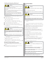 8
8
-
 9
9
-
 10
10
-
 11
11
-
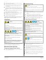 12
12
-
 13
13
-
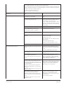 14
14
-
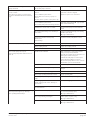 15
15
-
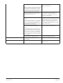 16
16
-
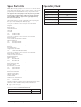 17
17
-
 18
18
-
 19
19
-
 20
20


Ask a question and I''ll find the answer in the document
Finding information in a document is now easier with AI
Related papers
-
Busch R5 KB 0020–0040 D/F User manual
-
Busch R 5 RC 0021 C Installation And Operating Instructions Manual
-
-
-
-
-
-
-
-
Other documents
-
VEVOR VP245 User manual
-
-
MasterCool 90066-BL Operating instructions
-
Koch Ultravac 250 Owner's manual
-
KSB Amacan P 1200-870 Installation & Operating Manual
-
Schmalz EVE-KL Operating Instructions Manual
-
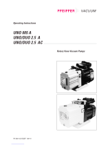 Pfeiffer Vacuum DUO 2.5 AC Operating Instructions Manual
-
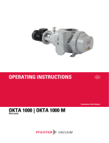 Pfeiffer Vacuum OKTA 6000 Operating Instructions Manual
-
Multitech 1777.8/7-10 G3 User manual
-

