Page is loading ...

WELDER • GENERATOR • AIR COMPRESSOR
BATTERY BOOSTER • HYDRAULIC PUMP
OPERATION MANUAL & PARTS LIST
©2013 Vanair Manufacturing, Inc.
All rights reserved
P/N: 090045-OP_r1
Effective Date:
11-2013
Read this manual before
installing, operating or
servicing this equipment.
Failure to comply with the
operation and maintenance
instructions in this manual
WILL VOID THE EQUIPMENT
WARRANTY.
NOTE
Making unauthorized
modifications to the system
components WILL VOID THE
WARRANTY!
Always inform Vanair
Manufacturing, Inc., before
beginning any changes to the
Air N Arc system.
NOTE
Use only Vanair Vanguard™
Premium Synthetic Oil and
Genuine Vanair Parts. Inspect
and replace damaged
components before operation.
Substituting non-Vanguard™
Oil or non-genuine Vanair filter
components WILL VOID THE
COMPRESSOR WARRANTY!
Vanair Manufacturing, Inc.
10896 West 300 North
Michigan City, IN 46360
Phone: (219) 879-5100
(800) 526-8817
Service Fax: (219) 879-5335
Parts Fax: (219) 879-5340
Sales Fax: (219) 879-5800
www.vanair.com
KEEP THE MANUAL
WITH THE VEHICLE
NOTE
This publication contains the
latest information available at
the time of preparation. Every
effort has been made to ensure
accuracy. However, Vanair
Manufacturing, Inc. takes no
responsibility for errors or
consequential damages
caused by reliance on the
information contained herein.
Vanair Manufacturing, Inc.
reserves the right to make
design change modifications
or improvements without prior
notification.

WARRANTY
Subject to the terms and conditions below, Vanair
®
Manufacturing Inc. warrants to the original end user that
new Air N Arc
®
equipment sold after the effective date of this limited warranty is free of defects in material
and workmanship at the time it was shipped from Vanair.
This statement of warranty is expressly in lieu of and disclaims all other express warranties, implied
warranties of merchantability and fitness for a particular purpose and all other implied warranties which
extend beyond the description on the face hereof. In no event shall Vanair be responsible for special, indirect,
incidental, consequential or punitive damages of any kind, including without limitation, lost profits or other
monetary loss, whether or not any such matters or causes are within Vanair’s control or due to negligence or
other fault of Vanair, its agents, affiliates, employees or representatives.
Within the warranty periods listed below, Vanair will repair or replace any warranted parts or components that
fail due to defects in material or workmanship. Warranty will commence upon receipt of the Warranty
Registration Card. If the Warranty Registration Card is not received within six (6) months, then warranty
commencement date shall be thirty (30) days from the date of shipment from Vanair. Records of warranty
adherence are the responsibility of end user.
When following the prescribed maintenance schedule, the rotary screw compressor unit is warranted by
Vanair for five (5) years, the hydraulic pump and battery for (1) year and all other major components for three
(3) years. (NOTE: Engines are warranted separately by the engine manufacturer.)
Consumable products such as filters and electrodes are not covered. This warranty does not cover damage
caused by accident, misuse or negligence.
Any disassembly of major components must be approved by Vanair to avoid voiding of warranty. The
Warranty-Service Department must be notified prior to any and all work being done on the equipment. Any
and all such claims for warranty consideration must be coordinated through the Warranty-Service
Department at the address below. Do not return parts without prior authorization.
Warranty claims must be pre-approved, and are limited to the supply of replacement parts falling within the
warranty period. Credit for labor required to refit replacement parts is NOT included. All warranted parts are
to be shipped PREPAID to Vanair. Replacement parts will be shipped back to the customer by Vanair via
ground shipment. Cost to expedite delivery of replacement parts will be incurred by customer. Factory
installed units will also include warranty on the installation for one year.
This warranty shall be void and Vanair shall have no responsibility to repair, replace or repay the purchase
price of defective or damaged parts resulting from the use of or repair of replacement parts or fluids not of
Vanair’s manufacture or from buyer’s failure to store, install, maintain and operate the equipment according
to the recommendations contained in the manual.
All claims under the warranty shall be made by contacting Vanair Warranty-Service Department.
Register Your Warranty Online at www.vanair.com under the Support Tab!
Or Call: (800) 526-8817 • Fax: (219) 879-5800
Mail to: 10896 W 300 North • Michigan City, IN 46360
Effective June 2011

AIR N ARC
®
I-300 SERIES ALL-IN-ONE POWER SYSTEM
®
TABLE OF CONTENTS
090045-OP_r1 PAGE - I
TABLE OF CONTENTS
WARRANTY ............................................... BEHIND COVER
TABLE OF CONTENTS......................................................I
WARRANTY CLAIMS PROCEDURE ..............................VII
CLAIMS PROCESS FOR WARRANTED PARTS....................................................................................VII
PROCEDURE ..........................................................................................................................................VII
SECTION 1: SAFETY ........................................................1
1.1 GENERAL INFORMATION ............................................................................................................1
1.2 DANGERS, WARNINGS, CAUTIONS, AND NOTES ....................................................................1
1.3 INTERNATIONAL SAFETY SYMBOL ............................................................................................2
1.4 ARC WELDING HAZARDS............................................................................................................2
1.4.1 ELECTRICAL SHOCK CAN KILL ...................................................................................................................... 2
1.4.2 FUMES AND GASSES CAN BE HAZARDOUS................................................................................................. 3
1.4.3 BUILD UP OF GAS CAN INJURE OR KILL....................................................................................................... 3
1.4.4 ENCLOSED SPACES CAN CAUSE A BUILD-UP OF NOXIOUS FUMES AND OVERHEATING .................... 3
1.4.5 ARC RAYS CAN BURN EYES AND SKIN ......................................................................................................... 3
1.4.6 WELDING CAN CAUSE FIRE AND EXPLOSION ............................................................................................. 4
1.4.7 FLYING METAL CAN INJURE EYES ................................................................................................................. 4
1.4.8 HOT PARTS CAN CAUSE SEVERE BURNS .................................................................................................... 4
1.4.9 NOISE CAN DAMAGE HEARING ...................................................................................................................... 4
1.4.10 MAGNETIC FIELDS CAN AFFECT PACEMAKERS ......................................................................................... 4
1.4.11 CYLINDERS CAN EXPLODE IF DAMAGED ..................................................................................................... 5
1.5 ENGINE HAZARDS ...........................................................................................................................5
1.5.1 BATTERY EXPLOSION CAN BLIND ................................................................................................................. 5
1.5.2 FUEL CAN CAUSE FIRE OR EXPLOSION ....................................................................................................... 5
1.5.3 MOVING PARTS CAN CAUSE INJURY............................................................................................................. 6
1.5.4 HOT PARTS CAN CAUSE SEVERE BURNS .................................................................................................... 6
1.5.5 ENGINE EXHAUST GASSES CAN KILL ........................................................................................................... 6
1.5.6 ENCLOSED SPACES CAN CAUSE A BUILD-UP OF NOXIOUS FUMES AND OVERHEATING .................... 6
1.5.7 BATTERY ACID CAN BURN SKIN AND EYES ................................................................................................. 6
Continued on next page...

TABLE OF CONTENTS AIR N ARC
®
I-300 SERIES ALL-IN-ONE POWER SYSTEM
®
PAGE - II 090045-OP_r1
SECTION 1: SAFETY (CONTINUED)
1.5.8 ENGINE HEAT CAN CAUSE FIRE......................................................................................................................6
1.5.9 EXHAUST SPARKS CAN CAUSE FIRE .............................................................................................................6
1.6 COMPRESSED AIR HAZARDS .................................................................................................... 6
1.6.1 BREATHING COMPRESSED AIR CAN CAUSE SERIOUIS INJURY OR DEATH.............................................6
1.6.2 ENCLOSED SPACES CAN CAUSE A BUILD-UP OF NOXIOUS FUMES AND OVERHEATING.....................7
1.6.3 COMPRESSED AIR CAN CAUSE INJURY ........................................................................................................7
1.6.4 TRAPPED AIR PRESSURE AND WHIPPING HOSES CAN CAUSE INJURY ..................................................7
1.6.5 HOT METAL FROM AIR ARC CUTTING AND GOUGING CAN CAUSE FIRE OR EXPLOSION .....................7
1.6.6 HOT PARTS CAN CAUSE SEVERE BURNS .....................................................................................................7
1.6.7 READ INSTRUCTIONS .......................................................................................................................................7
1.7 HYDRAULIC PUMP HAZARDS..................................................................................................... 7
1.7.1 CONTENTS UNDER PRESSURE .......................................................................................................................7
1.7.2 HEED PRESSURE LIMITS AND RECOMMENDATIONS...................................................................................7
1.7.3 HOSE AND TUBING INSPECTION.....................................................................................................................8
1.7.4 HOSE AND TUBING REPLACEMENT ...............................................................................................................8
1.7.5 HOT PARTS CAN CAUSE SEVERE BURNS .....................................................................................................8
1.7.6 HYDRAULIC CYLINDERS MAY HOLD A FUNCTION IN POSITION EVEN WHEN THE PUMP IS OFF..........8
1.7.7 HYDRAULIC PIPING REPLACEMENT MUST CONFORM TO SAEJ1065 SPECIFICATIONS.........................8
1.7.8 DO NOT HEAT HYDRAULIC PIPE......................................................................................................................8
1.7.9 RELIEVE HYDRAULIC SYSTEM PRESSURE BEFORE REMOVING ANY COMPONENTS
FROM THE SYSTEM ...........................................................................................................................................9
1.7.10 LIFTING COMPONENTS.....................................................................................................................................9
1.7.11 HYDRAULIC TEST GAUGES..............................................................................................................................9
1.7.12 SYSTEM MODIFICATION PROHIBITED.............................................................................................................9
1.7.13 FALLING UNIT CAN CAUSE INJURY ................................................................................................................9
1.7.14 REPLACE DAMAGED SAFETY DECALS..........................................................................................................9
1.7.15 POST-SERVICING OPERATION .........................................................................................................................9
1.7.16 WEAR PROPER PROTECTIVE EQUIPMENT ....................................................................................................10
1.7.17 KEEP CLEAR OF MOVING PARTS....................................................................................................................10
1.7.18 CONFINE LOOSE CLOTHING AND HAIR; REMOVE WATCHES, RINGS OR JEWELRY
DURING OPERATION .........................................................................................................................................10
1.8 ADDITIONAL SYMBOLS FOR INSTALLATION, OPERATION AND MAINTENANCE.................. 10
1.8.1 FALLING UNIT CAN CAUSE INJURY ................................................................................................................10
Continued on next page...

AIR N ARC
®
I-300 SERIES ALL-IN-ONE POWER SYSTEM
®
TABLE OF CONTENTS
090045-OP_r1 PAGE - III
SECTION 1: SAFETY (CONTINUED)
1.8.2 OVERHEATING CAN DAMAGE MOTORS ........................................................................................................ 10
1.8.3 FLYING SPARKS CAN CAUSE INJURY............................................................................................................ 10
1.8.4 OVERUSE CAN CAUSE OVERHEATING.......................................................................................................... 10
1.8.5 ENCLOSED SPACES CAN CAUSE A BUILD-UP OF NOXIOUS FUMES AND OVERHEATING .................... 10
1.8.6 TILTING OF TRAILER CAN CAUSE INJURY.................................................................................................... 11
1.8.7 READ INSTRUCTIONS ...................................................................................................................................... 11
1.8.8 H.F. RADIATION CAN CAUSE INTERFERENCE .............................................................................................. 11
1.8.9 ARC WELDING CAN CAUSE INTERFERENCE................................................................................................ 11
1.9. CALIFORNIA PROPOSITION 65 WARNINGS ..............................................................................11
1.10 PRINCIPAL SAFETY STANDARDS...............................................................................................12
1.11 EMF INFORMATION ......................................................................................................................12
1.12 MACHINE CANOPY ACCESS SAFETY SWITCHES.................................................................... 13
1.13 DISPOSING OF MACHINE FLUIDS ..............................................................................................13
SECTION 2: SPECIFICATIONS .........................................15
TABLE 2A: ENGINE, HYDRAULIC SYSTEM, WELDER AND GENERATOR SPECIFICATIONS ..........15
TABLE 2B: SPECIFICATIONS — AIR COMPRESSOR ..........................................................................16
TABLE 2C: SPECIFICATIONS — UNIT WEIGHT AND DIMENSIONS...................................................16
TABLE 2D: GENUINE VANGUARD™ OIL CHARACTERISTICS ...........................................................16
SECTION 3: INSTALLATION.............................................17
3.1 AIR N ARC I-300 SERIES ALL-IN-ONE MACHINE PACKAGE RECEIPT/INSPECTION ............17
3.2 GENERAL OVERVIEW OF INSTALLATION..................................................................................17
3.2.1 MACHINE CLEARANCE ALLOWANCE ............................................................................................................ 18
3.3 MOUNTING THE MACHINE ..........................................................................................................18
3.3.1 MACHINE STABILIZATION ................................................................................................................................ 18
3.4 CONNECTING THE FUEL SYSTEM .............................................................................................22
3.5 CONNECTNG AND APPLYING THE HYDRAULIC SYSTEM .......................................................22
3.6 INSTALLING THE REMOTE CONTROL PANEL ...........................................................................23
3.7 INSTALLING (OPTIONAL) REMOTE AIR TANK ...........................................................................23
3.8 FUEL LINE SIPHON ......................................................................................................................23
Continued on next page...

TABLE OF CONTENTS AIR N ARC
®
I-300 SERIES ALL-IN-ONE POWER SYSTEM
®
PAGE - IV 090045-OP_r1
SECTION 4: OPERATION .................................................25
4.1 GENERAL INFORMATION ........................................................................................................... 25
4.2 MACHINE START-UP AND SHUTDOWN PROCEDURE............................................................. 26
4.2.1 START-UP FROM MACHINE ..............................................................................................................................26
4.2.2 START UP FROM REMOTE CRANE..................................................................................................................26
4.2.3 MACHINE SHUTDOWN.......................................................................................................................................28
4.3 ENGINE THROTTLE CONTROL FUNCTIONS............................................................................. 28
4.4 OPERATING THE WELDER ......................................................................................................... 29
4.4.1 WELDER OPERATING PROCEDURE................................................................................................................29
4.4.1.1 CC (CONSTANT CURRENT) MODE...........................................................................29
4.4.1.2 CV (CONSTANT VOLTAGE) MODE - USING A VOLTAGE
SENSING SUITCASE FEEDEROR SPOOL GUN.......................................................30
4.5 OPERATING THE GENERATOR.................................................................................................. 31
4.6 OPERATING THE COMPRESSOR............................................................................................... 32
4.7 OPERATING THE BATTERY BOOSTER/CHARGER .................................................................. 32
4.7.1 CONNECTION - DISCONNECTION SEQUENCE AND OPERATION................................................................33
4.8 USING THE START OVERRIDE SWITH TO JUMP-START THE VEHICLE ................................ 33
4.9 OPERATING THE HYDRAULIC PUMP......................................................................................... 34
4.10 EXTREME CONDITION OPERATION .......................................................................................... 34
4.10.1 COLD WEATHER OPERATION ..........................................................................................................................34
4.10.2 HIGH TEMPERATURE OPERATION ..................................................................................................................35
4.10.3 HIGH DUST CONTENT OPERATION .................................................................................................................36
4.10.4 HIGH ALTITUDE OPERATION ............................................................................................................................36
SECTION 5: MAINTENANCE ............................................ 37
5.1 GENERAL INFORMATION ........................................................................................................... 37
5.2 ROUTINE MAINTENANCE SCHEDULE ....................................................................................... 37
TABLE 5A: MAINTENANCE SCHEDULE ............................................................................................... 39
5.3 REPLACEMENT PARTS ............................................................................................................... 44
5.4 PARTS REPLACEMENT AND ADJUSTMENT PROCEDURES ................................................... 44
5.4.1 ADJUSTING THE ENGINE SPEED.....................................................................................................................45
5.4.2 ADJUSTING THE PRESSURE SETTING ...........................................................................................................45
5.4.3 RE-TENSIONING AND REPLACING THE SERPENTINE DRIVE BELTS .........................................................46
5.4.3.1 RE-TENSIONING THE AIR COMPRESSOR SERPENTINE DRIVE BELT.................46
5.4.3.2 REPLACING THE AIR COMPRESSOR SERPENTINE DRIVE BELT.........................46
Continued on next page...

AIR N ARC
®
I-300 SERIES ALL-IN-ONE POWER SYSTEM
®
TABLE OF CONTENTS
090045-OP_r1 PAGE - V
SECTION 5: MAINTENANCE (CONTINUED)
5.4.3.3 RE-TENSIONING THE GENERATOR / HYDRAULIC PUMP SERPENTINE
DRIVE BELT ................................................................................................................ 48
5.4.3.4 REPLACING THE GENERATOR / HYDRAULIC PUMP SERPENTINE
DRIVE BELT ................................................................................................................ 49
5.4.3.5 RE-TENSIONING THE ENGINE HYDRAULIC PUMP DRIVE BELTS........................ 51
5.4.4 SERVICING THE SYSTEM FUSES AND CIRCUIT BREAKERS ...................................................................... 51
5.5 STORAGE AND INTERMITTENT USE .........................................................................................54
5.5.1 INTERMITTENT USE............................................................................................................................................... 54
5.5.2 LONG TERM STORAGE ......................................................................................................................................... 54
SECTION 6: TROUBLESHOOTING ................................55
6.1 GENERAL INFORMATION ............................................................................................................55
6.2 TROUBLESHOOTING GUIDE.......................................................................................................56
SECTION 7: ILLUSTRATED PARTS LIST ..................... 65
7.1 PARTS ORDERING PROCEDURE ...............................................................................................65
TABLE 7A: RECOMMENDED SPARE PARTS LIST...............................................................................66
7.2 AIR N ARC I-300 SYSTEMS ASSEMBLIES ................................................................................68
7.3 AIR STORAGE ASSEMBLY ..........................................................................................................70
7.4 COMPRESSOR AND PARTS ASSEMBLY (1 OF 2) .....................................................................72
7.4 COMPRESSOR AND PARTS ASSEMBLY (2 OF 2) .....................................................................74
7.5 COOLING SYSTEM .......................................................................................................................76
7.6 FRAME AND CANOPY ASSEMBLY (1 OF 2) ...............................................................................78
7.6 FRAME AND CANOPY ASSEMBLY (2 OF 2) ...............................................................................80
7.7 INSTRUMENT PANEL ...................................................................................................................82
7.8 GENERATORS AND PARTS.........................................................................................................84
7.9 HYDRAULIC PUMP ASSEMBLY (1 OF 3) ....................................................................................86
7.9 HYDRAULIC PUMP ASSEMBLY OPEN CENTER (2 OF 3) .........................................................88
7.9 HYDRAULIC PUMP ASSEMBLY CLOSED CENTER (3 OF 3).....................................................90
7.10 ENGINE AND DRIVE PARTS (1 OF 2)..........................................................................................92
7.10 ENGINE AND DRIVE PARTS (2 OF 2)..........................................................................................96
7.11 ELECTRICAL SYSTEM .................................................................................................................100
7.12 MANIFOLD ASSEMBLY ................................................................................................................102
7.13 HYDRAULIC TANK ASSEMBLY....................................................................................................104
Continued on next page...

TABLE OF CONTENTS AIR N ARC
®
I-300 SERIES ALL-IN-ONE POWER SYSTEM
®
PAGE - VI 090045-OP_r1
SECTION 7: ILLUSTRATED PARTS LIST (CONTINUED)
7.14 DECAL AND PLATE LOCATIONS (1 OF 4).................................................................................. 106
7.14 DECAL AND PLATE LOCATIONS (2 OF 4).................................................................................. 107
7.14 DECAL AND PLATE LOCATIONS (3 OF 4).................................................................................. 108
7.14 DECAL AND PLATE LOCATIONS (4 OF 4).................................................................................. 109
7.15 WIRING DIAGRAM - AIR N ARC I-300 SERIES......................................................................... 110
7.16 WIRING DIAGRAM - SWITCHES AND LIGHTS ........................................................................... 111
7.17 SCHEMATIC DIAGRAM - HYDRO CRANE, O.C., NO TOOL....................................................... 112
7.18 SCHEMATIC DIAGRAM - HYDRO CRANE, C.C., NO TOOL....................................................... 113
7.19 SCHEMATIC DIAGRAM - COMPRESSOR FLOW ....................................................................... 114
7.20 HOSE INSTALLATION GUIDE ...................................................................................................... 115

AIR N ARC
®
I-300 SERIES ALL-IN-ONE POWER SYSTEM
®
WARRANTY PROCEDURE
090045-OP_r1 PAGE - VII
C
LAIMS
PROCESS
FOR
WARRANTED
V
ANAIR
PARTS
This process must be used by owners of
Vanair
®
equipment in situations where a
warranted item needs repair or replacement
under the terms of the purchase warranty.
Do not return items to Vanair without prior
authorization from the Vanair Warranty
Administrator.
P
ROCEDURE
:
When a customer needs assistance in
troubleshooting a system and/or returning
parts, follow the steps below.
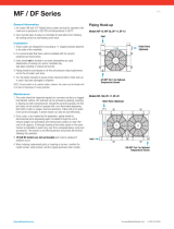
1. Locate the machine’s serial number:
The machine package serial number plate is
located inside the machine compartment on
the floor near to the generator mounting
location (see Figure W-1).
The engine and the compressor also have
individual serial numbers respectively (see
Figure W-1). For engine warranty issues,
consult the Engine Operator’s Manual for
the engine’s limited warranty details. For
particular compressor unit issues, the
compressor serial number may be needed.
In any case, engine and/or compressor
issues can be confirmed using the machine
serial number as found in Figure W-1.
2. Have a list of the symptoms/condition/
malfunctions along with any applicable
temperature and pressure readings, and
also the number of operational hours
available:
Note that the above information will also
need to be included on the Return Material
Authorization Form (per Step #6); this form
is necessary for warranty processing if the
warranty claim is deemed valid by the
service case review.
3. Contact the Vanair
®
Service Department
by phone (1-219-879-5100) to speak with
a Service Technician.
4. Vanair Service will troubleshoot the
problem based on the information
provided by the customer, and attempt to
return the unit to service as quickly as
possible.
5. If the unit cannot be returned to service,
and Vanair determines this matter is a
warranty issue, the Service Technician
will assign an RMA (Return Material
Authorization) number that will provide
for the return of the item to Vanair for
analysis and a final determination as to
the item’s warranty status.
6. Warranty Claims are solicited via a
Return Material Authorization (RMA)
Form. This form can be obtained via
download from the web site, or requested
directly from the Vanair Service
Department:
Once a current form has been obtained,
follow the instructions given on the form to fill
in the information needed. This form is used
for the purpose of soliciting a warranty case.
All of the field information except for the
bottom section block fields, which includes
NOTE
The RMA number must be placed on the
outside of the package being returned.
WARRANTY CLAIMS
PROCEDURE

WARRANTY PROCEDURE
AIR N ARC
®
I-300 SERIES ALL-IN-ONE POWER SYSTEM
®
PAGE - VIII 090045-OP_r1
KEY DESCRIPTION KEY DESCRIPTION
AMACHINE SERIAL PLATE / SERIAL # LOCATION CENGINE SERIAL NUMBER TAG
BCOMPRESSOR SERIAL PLATE / SERIAL #
LOCATION: Note alternative locations of plate
mounting
DWELDER GENERATOR SERIAL TAG
EAC GENERATOR SERIAL PLATE /
SERIAL # LOCATION
Figure W-1: Machine Serial Number Locations
E
D
C
A
PN
CO DE
KVA
COSPHI
D.C . V /A
BE ARIN GS
GE269530 SN 5XXX PHASE 1
SERVICE S1 INS. CL. H
6.8 V 120/240 A 55.7/28.3
1 Hz 60 RPM 3600
CON NECTION
II / I
Kg 23.7 IP 21 J .0098
6203 2ZC3 DATE 2011
10% OVER LOAD FOR 2 h I N A 24 h PERIOD
800 -5 26- 881 7 ww w .va na ir.co m
INSULATION SYSTEM
DIV-180-3 LOC. 2
C US
187963
B

AIR N ARC
®
I-300 SERIES ALL-IN-ONE POWER SYSTEM
®
WARRANTY PROCEDURE
090045-OP_r1 PAGE - IX
Disposition of Goods, Notifications and
Additional Notes, will be required.
Customers have 30 days after the RMA
number is issued to return the item. If the
part is not returned within this period, the
RMA is void and any claims will be denied.
Before sending a warranty part to a
customer, Vanair
®
will need a P.O. or credit
card number to cover the cost of the part and
shipping. After the part is analyzed and
deemed to be covered under warranty,
Vanair will issue credit to the customer. All
parts eligible for warranty must have the
RMA number on the invoice at the time of
purchase.
No items can be returned “freight collect”.
Freight costs will be addressed at the time
the claim is closed. The customer pays any
additional costs for warranty parts delivered
through expedited services (i.e., Next Day,
Second Day).
VANAIR WILL NEVER ACCEPT ANY
INVOICES FOR PARTS RETURNED: ANY
PARTS RETURNED VIA INVOICE WILL BE
RETURNED FREIGHT COLLECT: NO
PARTS ARE TO BE RETURNED FREIGHT
COLLECT!
Vanair Mfg., Inc. strives to continuously
improve its customer service. Please forward
any questions, comments, or suggestions to
Vanair Service (219-879-5100, ext. 400) or
e-mail us (service@vanair.com).
NOTE
All labor claims or invoices must be
approved by the Vanair Warranty
Administrator prior to starting repair work
along with the cost of the repair. All paper
work associated with the returned item
and warranty repair cost must reference
the RMA number issued against the part,
and be forwarded to Vanair within 30 days
of the completion of work.

PAGE - X 090045-OP_r1
BLANK PAGE

AIR N ARC
®
I-300 SERIES ALL-IN-ONE POWER SYSTEM
®
SECTION 1: SAFETY
090045-OP_r1 PAGE - 1
1.1 GENERAL INFORMATION
The products provided by Vanair
®
Manufacturing, Inc., are designed and
manufactured for safe operation and
maintenance. But it is ultimately the
responsibility of the users and maintainers
for safe use of this equipment. Part of this
responsibility is to read and be familiar with
the contents of this manual before operation
or performing maintenance actions.
1.2 DANGERS, WARNINGS,
CAUTIONS, AND NOTES
Specific safety and operation information
given throughout the manual may be
presented within a separate bordered frame
and header for easy and clear identification.
Those issues that regard safety measures
are also tagged with the international safety
symbol (see Section 1.3), and should
always be taken into consideration before
performing an operation. Specific definitions
of theses bordered instructions are as
follows:
IMPORTANT
It is mandatory that all operators read this
manual before operating or servicing the Air
N Arc
I-
300 Series All-In-One Power
System. Failure to do so could result in
death, bodily injury or damage to
equipment.
DANGER
Identifies actions or conditions which will
cause death, severe injury, equipment
damage or destructive malfunctions.
WARNING
Identifies actions or conditions which
may cause death, severe injury,
equipment damage or destructive
malfunctions.
CAUTION
Identifies actions or conditions which will
or can cause injuries, equipment damage
or malfunctions.
IMPORTANT
Additional information (or existing
information) which must be brought to the
attention of operators/maintainers
affecting safety, operation, maintenance,
or warranty requirements.
NOTE
Additional information (or existing
information) which should be brought to
the attention of operators/maintainers
affecting safety, operation, maintenance,
or warranty requirements.
SECTION 1:
SAFETY

SECTION 1: SAFETY AIR N ARC
®
I-300 SERIES ALL-IN-ONE POWER SYSTEM
®
PAGE - 2 090045-OP_r1
1.3 INTERNATIONAL SAFETY
SYMBOL -
The symbols shown and defined in Section
1: Safety are used throughout this manual to
call attention to and identify possible
hazards.
The international warning symbol shown
above is used on all decals, labels and signs
that concern information pertaining to bodily
harm. When you see the international
warning symbol, pay extremely careful
attention, and follow the given instructions
or indications to avoid any possible hazard.
1.4 ARC WELDING HAZARDS
1.4.1
ELECTRICAL SHOCK CAN KILL
Touching live electrical parts
can cause fatal shocks or
severe burns. The electrode
and work circuit is
electrically live whenever the
output is on. The input
power circuit and machine internal circuits
are also live when power is on. In semi-
automatic or automatic wire welding, the
wire, wire reel, drive roll housing, and all
metal parts touching the welding wire are
electrically live. Incorrectly installed or
improperly grounded equipment is a hazard.
DO NOT weld with the electrode holder
connected to the negative (-) port, and the
work piece connected to the vehicle: Bodily
harm and equipment damage may occur.
DO NOT touch live electrical parts.
Wear dry, hole-free insulating gloves and
body protection.
Insulate yourself from work and ground using
dry insulating mats or covers big enough to
prevent any physical contact with the work or
ground.
DO NOT use AC output in damp areas, if
movement is confined, or if there is a danger
of falling.
Additional safety precautions are required
when working in electrically hazardous
conditions such as in damp locations or while
wearing wet clothing; on metal structures
such as floors, gratings, or scaffolds; when in
cramped positions such as sitting, kneeling,
or lying; or when there is a high risk of
unavoidable or accidental contact with the
work piece or ground.
DO NOT work alone!
Disconnect input power or stop engine
before installing or servicing this equipment.
Lockout/tag out input power according to
OSHA29 CFR1910.147 (see Section 1.10,
Principal Safety Standards).
Properly install and ground this equipment
according to its Owner’s Manual and
national, state, and local codes.
Always verify the supply ground: check and
ensure that input power cord ground wire is
properly connected to ground terminal in
disconnect box or that cord plug is connected
to a properly grounded receptacle outlet.
When making input connections, attach
proper grounding conductor first and double-
check connections.
Frequently inspect input power cord for
damage or bare wiring; replace cord
immediately if damaged—bare wiring can
kill.
Turn off all equipment when not in use.
DO NOT use worn, damaged, undersized, or
poorly spliced cables.
DO NOT drape cables over your body.
If earth grounding of the work piece is
required, ground it directly with a separate
cable.
DO NOT touch electrode if you are in contact
with the work, ground, or another electrode
from a different machine.
Use only well-maintained equipment. Repair
or replace damaged parts at once. Maintain
unit according to manual.
DO NOT touch electrode holders connected
to two welding machines at the same time

AIR N ARC
®
I-300 SERIES ALL-IN-ONE POWER SYSTEM
®
SECTION 1: SAFETY
090045-OP_r1 PAGE - 3
since double open-circuit voltage will be
present.
Wear a safety harness if working above floor
level.
Keep all panels and covers securely in place.
Clamp work cable with good metal-to-metal
contact to work piece or work table as near
the weld as practical.
Insulate work clamp when not connected to
workpiece to prevent contact with any metal
object.
DO NOT connect more than one electrode or
work cable to any single weld output
terminal.
1.4.2 FUMES AND GASSES CAN BE
HAZARDOUS
Welding produces fumes and
gasses. Breathing these
fumes and gasses can be
hazardous to your health.
Keep your head out of the
fumes. DO NOT breathe the fumes.
If inside, ventilate the area and/or use local
forced ventilation at the arc to remove
welding fumes and gasses.
If ventilation is poor, wear an approved air-
supplied respirator.
Read and understand the Material Safety
Data Sheets (MSDS’s) and the
manufacturer’s instructions for metals,
consumables, coatings, cleaners, and
degreasers.
Work in a confined space only if it is well
ventilated, or while wearing an air-supplied
respirator. Always have a trained watch
person nearby.
Welding fumes and gasses can displace air
and lower the oxygen level causing injury or
death. Be sure the breathing air is safe.
DO NOT weld in locations near degreasing,
cleaning, or spraying operations.
The heat and rays of the arc can react with
vapors to form highly toxic and irritating
gases.
DO NOT weld on coated metals, such as
galvanized, lead, or cadmium-plated steel,
unless the coating is removed from the weld
area, the area is well-ventilated, and while
wearing an air-supplied respirator. The
coatings and any metals containing these
elements can give off toxic fumes if welded.
1.4.3
BUILD UP OF GAS CAN INJURE
OR KILL
Shut off shielding gas supply
when not in use.
Always ventilate confined
spaces or use approved air-
supplied respirator.
1.4.4
ENCLOSED SPACES CAN
CAUSE A BUILD-UP OF NOXIOUS
FUMES AND OVERHEATING
DO NOT use in enclosed
spaces where deadly exhaust
gasses can build up and
machine can overheat,
causing fire.
1.4.5
ARC RAYS CAN BURN EYES AND
SKIN
Arc rays from the welding
process produce intense
visible and invisible (ultraviolet
and infrared) rays that can
burn eyes and skin. Sparks fly
off from the weld.
Wear an approved welding helmet fitted with
a proper shade of filter lenses to protect your
face and eyes from arc rays and sparks
when welding or watching.
(See ANSI Z49.1 and Z87.1 listed in Safety
Standards). Wear approved safety glasses
with side shields under your helmet.
Use protective screens or barriers to protect
others from flash, glare, and sparks; warn
others not to watch the arc.

SECTION 1: SAFETY AIR N ARC
®
I-300 SERIES ALL-IN-ONE POWER SYSTEM
®
PAGE - 4 090045-OP_r1
Wear protective clothing made from durable,
flame-resistant material (leather, heavy
cotton, or wool) and foot protection.
1.4.6
WELDING CAN CAUSE FIRE AND
EXPLOSION
Welding on closed containers,
such as tanks, drums, or pipes,
can cause them to blow up.
Sparks can fly off from the
welding arc. The flying sparks,
hot workpiece, and hot equipment can cause
fires and burns. Accidental contact of
electrode to metal objects can cause sparks,
explosion, overheating, or fire. Check and be
sure the area is safe before doing any
welding.
Remove all flammables within 35 ft (10.7 m)
of the welding arc. If this is not possible,
tightly cover them with approved covers.
DO NOT weld where flying sparks can strike
flammable material.
Protect yourself and others from flying
sparks and hot metal.
Be alert that welding sparks and hot
materials from welding can easily go through
small cracks and openings to adjacent
areas.
Watch for fire, and keep a fire extinguisher
nearby.
Be aware that welding on a ceiling, floor,
bulkhead, or partition can cause fire on the
hidden side.
DO NOT weld on closed containers such as
tanks, drums, or pipes, unless they are
properly prepared according to AWSF4.1
(See Section 1.10, Principal Safety
Standards).
Connect ground cable as close to the
welding area as practical to prevent welding
current from traveling long, possibly
unknown paths and causing electric shock,
sparks, and fire hazards.
DO NOT use welder to thaw frozen pipes.
Remove stick electrode from holder or cut off
welding wire at contact tip when not in use.
Wear oil-free protective garments such as
leather gloves, heavy shirt, cuffless trousers,
boots, and a cap.
Remove any combustibles, such as a butane
lighter or matches, from your person before
doing any welding.
Follow requirements in OSHA1910.252 (a)
(2) (iv) and NFPA 51B for hot work and have
a fire watcher and extinguisher nearby.
1.4.7 FLYING METAL CAN INJURE EYES
Sparks and flying metal can
be caused by welding,
chipping, wire brushing, and
grinding. As welds cool,
they can throw off slag.
Wear approved safety glasses with side
shields even under your welding helmet.
1.4.8
HOT PARTS CAN CAUSE
SEVERE BURNS
DO NOT touch hot parts
bare handed.
Allow cooling period before
working on equipment.
1.4.9
NOISE CAN DAMAGE HEARING
To handle hot parts, use
proper tools and/or wear
heavy, insulated welding
gloves and clothing to prevent
burns.
Noise from some processes or equipment
can damage hearing. Wear approved ear
protection if noise level is high.
1.4.10
MAGNETIC FIELDS CAN
AFFECT PACEMAKERS
Pacemaker wearers keep
away. Wearers should consult
their doctor before going near

AIR N ARC
®
I-300 SERIES ALL-IN-ONE POWER SYSTEM
®
SECTION 1: SAFETY
090045-OP_r1 PAGE - 5
arc welding, gouging, or spot welding
operations.
Shielding gas cylinders contain gas under
high pressure. If damaged, a cylinder can
explode. Since gas cylinders are normally
part of the welding process, be sure to treat
them carefully.
1.4.11
CYLINDERS CAN EXPLODE IF
DAMAGED
Protect compressed gas
cylinders from excessive
heat, mechanical shocks,
physical damage, slag, open
flames, sparks, and arcs.
Install cylinders in an upright position by
securing to a stationary support or cylinder
rack to prevent falling or tipping.
Keep cylinders away from any welding or
other electrical circuits.
Never drape a welding torch over a gas
cylinder.
Never allow a welding electrode to touch any
cylinder.
Never weld on a pressurized
cylinder—explosion will result.
Use only correct shielding gas cylinders,
regulators, hoses, and fittings designed for
the specific application; maintain them and
associated parts in good condition.
Turn face away from valve outlet when
opening cylinder valve.
Keep protective cap in place over valve
except when cylinder is in use or connected
for use.
Use the right equipment, correct procedures,
and sufficient number of persons to lift and
move cylinders.
Read and follow instructions on compressed
gas cylinders, associated equipment, and
Compressed Gas Association (CGA)
publication P-1 listed in Safety Standards.
1.5 ENGINE HAZARDS
1.5.1
BATTERY EXPLOSION CAN
BLIND
Always wear a face shield,
rubber gloves, and protective
clothing when working on a
battery.
Stop engine before
disconnecting or connecting battery cables
or servicing battery.
DO NOT allow tools to cause sparks when
working on a battery.
DO NOT use weld mode to charge batteries
or jump start vehicles.
Observe correct polarity (+ and −) on
batteries.
Disconnect negative (−) cable first and
connect it last.
1.5.2
FUEL CAN CAUSE FIRE OR
EXPLOSION
Stop engine and let it cool
down before checking or
adding fuel.
Always keep nozzle in contact
with tank when fueling.
DO NOT mix gasoline or alcohol with diesel
fuel.
DO NOT add fuel while smoking or if unit is
near any sparks or open flames.
IMPORTANT
Operator must be familiar with all safety
precautions listed in the Engine Operator’s
Manual, in addition to the safety issues
listed in this section.

SECTION 1: SAFETY AIR N ARC
®
I-300 SERIES ALL-IN-ONE POWER SYSTEM
®
PAGE - 6 090045-OP_r1
DO NOT overfill tank—allow room for fuel to
expand.
DO NOT spill fuel. If fuel is spilled, clean up
before starting engine.
Dispose of rags in a fireproof container.
1.5.3
MOVING PARTS CAN CAUSE
INJURY
Keep away from fans, belts, and
rotors. Keep all doors, panels,
covers, and guards closed and
securely in place.
Stop engine before installing or connecting
unit.
Have only qualified people remove doors,
panels, covers, or guards for maintenance
and troubleshooting as necessary.
Disconnect negative (−) battery cable from
battery to prevent accidental starting during
servicing.
Keep hands, hair, loose clothing, and tools
away from moving parts.
Reinstall doors, panels, covers, or guards
when servicing is finished and before starting
engine.
Before working on generator, remove spark
plugs or injectors to keep engine from kicking
back or starting.
Block flywheel so that it will not turn while
working on generator components.
1.5.4
HOT PARTS CAN CAUSE
SEVERE BURNS
DO NOT touch hot parts bare
handed.
Allow cooling period before
working on equipment.
1.5.5
ENGINE EXHAUST GASSES CAN
KILL
If used in a closed area, vent
engine exhaust outside and
away from any building air
intakes.
Check the fuel system at a well-ventilated,
open space.
1.5.6
ENCLOSED SPACES CAN
CAUSE A BUILD-UP OF NOXIOUS
FUMES AND OVERHEATING
DO NOT use in enclosed
spaces where deadly
exhaust gasses can build up
and machine can overheat,
causing fire.
1.5.7
BATTERY ACID CAN BURN SKIN
AND EYES
DO NOT tip battery.
Replace damaged battery.
Flush eyes and skin
immediately with water.
1.5.8
ENGINE HEAT CAN CAUSE FIRE
DO NOT locate unit on, over,
or near combustible surfaces
or flammables.
Keep exhaust and exhaust
pipes way from flammables.
1.5.9
EXHAUST SPARKS CAN CAUSE
FIRE
Use approved engine exhaust
spark arrester in required
areas — see applicable codes.
1.6 COMPRESSED AIR
HAZARDS
1.6.1
BREATHING COMPRESSED AIR
CAN CAUSE SERIOUS INJURY
OR DEATH
DO NOT use compressed air for
breathing. Use only for cutting,
gouging, and tools.

AIR N ARC
®
I-300 SERIES ALL-IN-ONE POWER SYSTEM
®
SECTION 1: SAFETY
090045-OP_r1 PAGE - 7
1.6.2
ENCLOSED SPACES CAN
CAUSE A BUILD-UP OF
NOXIOUS FUMES AND
OVERHEATING
DO NOT use in enclosed
spaces where deadly
exhaust gasses can build
up and machine can
overheat, causing fire.
1.6.3
COMPRESSED AIR CAN CAUSE
INJURY
Wear approved safety
goggles.
DO NOT direct air stream
toward self or others.
1.6.4
TRAPPED AIR PRESSURE AND
WHIPPING HOSES CAN CAUSE
INJURY
Release air pressure from
tools and system before
servicing, adding or changing
attachments, or opening
compressor oil drain or oil fill
cap.
1.6.5 HOT METAL FROM AIR ARC
CUTTING AND GOUGING CAN
CAUSE FIRE OR EXPLOSION
DO NOT cut or gouge near
flammables.
Watch for fire; keep
extinguisher nearby.
1.6.6
HOT PARTS CAN CAUSE
SEVERE BURNS
DO NOT touch hot parts bare
handed.
Allow cooling period before
working on equipment.
1.6.7
READ INSTRUCTIONS
Read Owner’s Manual before
using or servicing unit.
Stop engine and release air
pressure before servicing.
Use only genuine Air N Arc replacement
parts.
1.7 HYDRAULIC PUMP
HAZARDS
1.7.1
CONTENTS UNDER PRESSURE
DO NOT operate the hydraulic
system if a leak is present.
Serious injury may result.
Hydraulic systems operate
under very high-pressure. Hydraulic fluid
escaping from a pressurized system can
penetrate unprotected body tissue. DO NOT
inspect for hydraulic leaks with bare hands
or other exposed body parts. As a minimum,
wear leather gloves prior to inspecting for
leaks and use cardboard or wood. If leaks
are present, relieve pressure and allow
system to cool prior to servicing. If injured by
escaping hydraulic oil, contact a physician
immediately. Serious complications may
arise if not treated immediately. If you have
questions regarding inspecting for hydraulic
leaks, please contact Vanair
®
prior to
servicing.
1.7.2 HEED PRESSURE LIMITS AND
RECOMMENDATIONS
Increasing hydraulic pressure
beyond the recommendations
may result in serious damage
to the pump and system or
serious personal injury and
may void the Vanair Warranty. If you have
questions concerning hydraulic pressures or
testing procedures, please contact Vanair
before attempting the test procedures or
making adjustments.

SECTION 1: SAFETY AIR N ARC
®
I-300 SERIES ALL-IN-ONE POWER SYSTEM
®
PAGE - 8 090045-OP_r1
1.7.3 HOSE AND TUBING INSPECTION
Hydraulic hoses and tubing
must be inspected on a daily
basis for leaks, cuts, abrasions,
damage and improper
clearance along any mounting
frame for hidden damage before the unit is
put into service. Replace damaged hoses or
hoses you suspect are damaged before the
system is returned to service! Hoses must be
replaced every two years. Failure to properly
inspect and maintain the system may result
in serious injury.
1.7.4 HOSE AND TUBING
REPLACEMENT
Use correct hoses, fittings, and adapters with
the correct SAE rating when replacing hoses
to prevent possible serious injury. Always
replace hoses, fittings, and adapters with
replacements that have a proper, suitable,
working pressure rating. Replacement hoses
must be of the correct length and must
comply with the hose manufacturer’s and
Vanair’s installation guidelines and
recommendations.
Hydraulic hoses have the SAE ratings
marked on the hose to assist you in selecting
the correct hose. The same manufacturer
must supply any replacement hydraulic
hoses and fitting assemblies. As an
example: Brand “X” hose and brand “Y”
fitting will not normally be compatible. No
“Twist” is allowed in the hydraulic hoses.
“Twist” may result in premature hose failure.
This can cause serious injury. Please contact
Vanair
®
for assistance when required.
1.7.5 HOT PARTS CAN CAUSE
SEVERE BURNS
Hydraulic systems are hot. DO
NOT TOUCH! Serious
personal injury may result from
hot oil. When you have
completed working on the
hydraulic system, thoroughly clean any
spilled oil from the equipment. DO NOT spill
any hydraulic fluids on the ground. Clean
any hydraulic fluids from your skin as soon
as you have completed maintenance and
repairs. Dispose of used oil and system
filters as required by law.
1.7.6 HYDRAULIC CYLINDERS MAY
HOLD A FUNCTION IN POSITION
EVEN WHEN THE PUMP IS OFF
Hydraulic cylinders can be holding a function
in a certain position when the pump is OFF.
An example of this is a function being held in
the lift or partial lift position by the cylinders.
If a hydraulic line is removed or the hydraulic
circuits or controls are being worked on,
gravity may allow the function being held in
position to drop. All workers and personnel
must remain clear of these areas when
working on or operating the hydraulic
system. Block and secure all devices and
functions which apply before beginning work
or operation. Failure to comply with this can
result in serious injury or death.
1.7.7 HYDRAULIC PIPING
REPLACEMENT MUST CONFORM
TO SAEJ1065 SPECIFICATIONS
Any hydraulic pipe that is replaced must
conform to SAE J1065 specifications. If
incorrect hydraulic pipe is installed, the
hydraulic system may fail, causing serious
injury. Damaged or leaking fittings, pipes or
hoses must be replaced before the system is
returned to service.
1.7.8 DO NOT HEAT HYDRAULIC PIPE
DO NOT heat hydraulic pipe.
The carbon content of this
steel tube is such that if
heated for bending, and
either water or air quenched,
the pipe may lose its ductility
and thereby be subject to failure under high-
pressure conditions. Serious injury can
result. Damaged or leaking pipes must be
replaced before the system is returned to
service. Please contact Vanair
®
if you
require assistance or have questions.
/