Page is loading ...

SL75
SL75H
SL SERIES
Installation, Operation and Maintenance Manual
Model: SL75 and SL75H shown

1.800.627.44992
S L- S e ri es
ERV
RISK OF ELECTRIC SHOCK OR EQUIPMENT DAMAGE
Whenever electrical wiring is connected, disconnected or
changed, the power supply to the ERV and its controls must
be disconnected. Lock and tag the disconnect switch or
circuit breaker to prevent accidental reconnection of
electric power.
CAUTION
Only persons who have been properly trained and autho-
rized are to access the ERV electrical box and the controller.
Changes to the controller are to be made only by trained
and authorized personnel.
IMPORTANT
RISK OF INJURY FROM FALLING OBJECTS
Installation of this unit requires hoisting hardware overhead
and working directly beneath heavy objects during the
installation process. Observe all OSHA-approved work
practices. Always wear OSHA-approved Personal Protective
Equipment (PPE).
CAUTION
RISK OF CONTACT WITH HIGH SPEED MOVING PARTS
This appliance has two high speed fans that can cause
injury or be damaged if objects come into contact with the
impellers when they are spinning. The fans may be con-
trolled by external controlling devices and switch on at any
time. When working in the area of the fans, electric power
to the unit must be disconnected.
CAUTION
This equipment is to be installed by following industry best
practices and all applicable codes. Any damage to
components, assemblies, subassemblies or the cabinet
which is caused by improper installation practices will void
the warranty.
IMPORTANT
All ductwork is to be designed and installed in accordance
with SMACNA guidelines.
IMPORTANT
This ERV is intended for ducted ventilation only. Ducting at
least 40 inches [1 meter] in length must be installed on all
four airstreams.
IMPORTANT

31.800.627.4499
S L- S e ri es ERV
Record information as shown below. In the unlikely event that factory assistance is ever
required, this information will be needed.
ERV Model:
Locate the RenewAire unit label, to be found outside of the appliance, near the terminal block.
Record the model and serial numbers below.
NOTE: This information is for purposes of identifying the specific air handling appliance. Unit-
specific option data can then be obtained, as needed, from the Model Number.
UNIT INFORMATION
OWNER INFORMATION
READ AND SAVE THIS MANUAL/LIRE ET CONSERVER CE MANUEL
This manual has space for recording operating settings at time of unit commissioning that
must be completed by the installer. See Sections 5.1 and 5.2 of this manual.
Information that is recorded is specific to just one ERV. If additional ERVs are being
documented, please make copies of these pages and identify each copy by its unit tag.
NOTICE
SL75
SL75H
UNIT INFORMATION
UNIT LABEL (TYPICAL)
Serial Number:

1.800.627.44994
Subject to change without notice: RENEWAIRE.COM | 1.800.627.4499 76 Subject to change without notice: RENEWAIRE.COM | 1.800.627.4499
SPECIFICATIONS & DIMENSIONS
SPECIFICATIONS
Ventilation Type:
Static plate, heat and humidity transfer
Typical Airflow Range: 30–130 CFM
Unit is HVI Tested/Certified per CSA C439
Protocol: Using one L-30-G5 Core
Standard Features:
White painted cabinet
Line-cord power supply
Low-voltage circuit for controls
Unit may be mounted in any orientation
Cross-core differential pressure ports
Dial-A-Flow: balance and airflow adjustment
Variable speed
Boost-mode
Controls:
Onboard digital controller with independent
variable speeds
Filters:
Total qty. 2, MERV 8, spun-polyester media:
7 1/2" x 10 1/2" x 1"
Unit Weight: 35 lbs.
Max. Shipping Dimensions & Weight (in carton):
31 1/4" L x 22 3/8" W x 14 3/8" H
41 lbs.
Motor(s):
Qty. 2, 120V EC motorized impellers
Accessories:
Backdraft damper: 6", 8"
Automatic balancing damper: 4", 5", 6"
Louvered wall vent 6": white, brown
Louvered wall vent 8": taupe vinyl, galvanized,
paintable galvanneal
Louvered wall vent with 8" round duct connection:
12" W x 8" H
Digital time clock: wall mount (TC7D-W),
in exterior enclosure (TC7D-E)
Carbon dioxide sensor/control: wall mount (CO2-W)
IAQ sensor: wall mount (IAQ-W)
Motion occupancy sensor/control:
ceiling mount (MC-C), wall mount (MC-W)
Push-button boost timer (PBT)
Percentage timer control (PTL)
Percentage timer control with furnace interlock (FM)
Push-button point-of-use controls (PBL), PTL req’d.
MERV 13 filter: OA airstream (shipped loose)
Wall bracket kit
Electric duct heater: RH series (1–4 kW);
designed for indoor ductwork installation only
75SL Energy Recovery Ventilator
EC Motor
Watts Volts Hz Phase
FLA
per
motor
Min.
Cir.
Amps
Max.
Overcurrent
Protection
Device
53 120 60 1 0.85 10 10
ELECTRICAL DATA
EC MOTOR OPERATING RANGE
0
0.2
0.4
0.6
0.8
1
1.2
1.4
1.6
1.8
0 20 40 60 80 100 120 140
ESP
CFM
= Actual tested
sample points
| = Operating Curves,
airflow is held
constant as static
pressure varies
Note: Watts is for the entire unit.
Note: Airflow performance includes effect of clean, standard filter
supplied with unit.
Note: Refer to CORES for specific operating point electrical data.
Sample Points Depicted in Larger Dots
Airflow (CFM)
External Static
Pressure
(Inches Water
Column)
Unit Power
Consumption
(Watts)
Max. Speed
138 0.1 135
131 0.2 134
125 0.3 133
117 0.4 132
110 0.5 131
102 0.6 129
95 0.7 126
87 0.8 123
78 0.9 119
68 1.0 114
49 1.2 102
34 1.4 81
Min. Speed
26 0.1 11
11 0.2 9
INDOOR UNIT NEW
Note: These are core-only ratings and are not HVI certified. Total EFF% calculated at 35/33wb OA and 70/58wb RA (winter)
and 98/78wb OA and 75/63wb RA (summer). HVI ratings apply to complete units only. This unit is HVI certified. See
HVI certified ratings on pg. 46 of Single/Multi-Family Catalog and at hvi.org.
CORE PERFORMANCE
Airflow (CFM) Sensible EFF% Total EFF% Winter/Summer
Max. Speed
138 63 54/36
131 64 55/38
125 65 57/40
117 67 59/42
110 68 60/44
102 69 62/46
95 70 64/48
87 72 66/51
78 73 68/53
68 75 70/56
49 78 75/61
34 82 78/66
Min. Speed
26 84 80/68
11 87 83/72

51.800.627.4499
Subject to change without notice: RENEWAIRE.COM | 1.800.627.4499 76 Subject to change without notice: RENEWAIRE.COM | 1.800.627.4499
SPECIFICATIONS & DIMENSIONS
AIRFLOW ORIENTATION
Available as shown in dimension drawing.
UNIT MOUNTING & APPLICATION
Can be mounted in any orientation. RA/EA
airstream can be switched with OA/SA airstream.
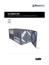
SL75 Energy Recovery Ventilator EC Motor
4 1/8" Typ.
4 1/8" Typ.
10 3/8" Typ.
SA
RA
OA
EA
34" Line Cord
Pressure Ports
(4) Typ.
9 1/2"
Overall
7 5/8" Minimum
Service Area
(Door can be
removed from
hinges.)
18 3/4"
19 7/8" Minimum
Service Area
2 1/8"
Minimum
Latch
Clearance
21 1/4" Overall
(With Hanging Brackets)
9 1/8"
Case
Door
Swing
2" Typ.
26 3/4" Case
4 1/4" Typ.
30 3/4" Overall
19" Case
6" Nominal Typ.
8" Nominal Typ.
22 1/4"- 23 1/4" Overall
With Ceiling Brackets
20 3/8" Overall
Control
Terminals
LEFT VIEW
(Hard Mount Depicted)
(Line Cord Hidden)
FRONT VIEW
RIGHT VIEW
(Hanging Mount Depicted)
TOP VIEW
Model: SL75
Drawing Type: Unit Dimension
Version: MAY22
ABBREVIATIONS
EA: Exhaust Air to outside
OA: Outside Air intake
RA: Room Air to be exhausted
SA: Supply Air to inside
INSTALLATION ORIENTATION
Unit may be installed in any
orientation.
NOTE
1.UNLESS OTHERWISE SPECIFIED,
DIMENSIONS ARE ROUNDED TO THE
NEAREST EIGHTH OF AN INCH.
2.SPECIFICATIONS MAY BE SUBJECT
TO CHANGE WITHOUT NOTICE.

1.800.627.44996
Subject to change without notice: RENEWAIRE.COM | 1.800.627.4499 54 Subject to change without notice: RENEWAIRE.COM | 1.800.627.4499
SPECIFICATIONS & DIMENSIONS
SPECIFICATIONS
Ventilation Type:
Static plate, heat and humidity transfer
Typical Airflow Range: 30–130 CFM
Unit is HVI Tested/Certified per CSA C439
Protocol: Using one L-30-G5 Core
Standard Features:
White painted cabinet
Hard wired to junction box
Low-voltage circuit for controls
Unit may be mounted in any orientation
Cross-core differential pressure ports
Dial-A-Flow: balance and airflow adjustment
Variable speed
Boost-mode
Controls:
Onboard digital controller with independent
variable speeds
Filters:
Total qty. 2, MERV 8, spun-polyester media:
7 1/2" x 10 1/2" x 1"
Unit Weight: 35 lbs.
Max. Shipping Dimensions & Weight (in carton):
31 1/4" L x 22 3/8" W x 14 3/8" H
41 lbs.
Motor(s):
Qty. 2, 120V EC motorized impellers
Accessories:
Backdraft damper: 6", 8"
Automatic balancing damper: 4", 5", 6"
Louvered wall vent 6": white, brown
Louvered wall vent 8": taupe vinyl, galvanized,
paintable galvanneal
Louvered wall vent with 8" round duct connection:
12" W x 8" H
Digital time clock: wall mount (TC7D-W),
in exterior enclosure (TC7D-E)
Carbon dioxide sensor/control: wall mount (CO2-W)
IAQ sensor: wall mount (IAQ-W)
Motion occupancy sensor/control:
ceiling mount (MC-C), wall mount (MC-W)
Push-button boost timer (PBT)
Percentage timer control (PTL)
Percentage timer control with furnace interlock (FM)
Push-button point-of-use controls (PBL), PTL req’d.
MERV 13 filter: OA airstream (shipped loose)
Wall bracket kit
Electric duct heater: RH series (1–4 kW);
designed for indoor ductwork installation only
75HSL Energy Recovery Ventilator
EC Motor
Watts Volts Hz Phase
FLA
per
motor
Min.
Cir.
Amps
Max.
Overcurrent
Protection
Device
53 120 60 1 0.85 10 10
ELECTRICAL DATA
EC MOTOR OPERATING RANGE
0
0.2
0.4
0.6
0.8
1
1.2
1.4
1.6
1.8
0 20 40 60 80 100 120 140
ESP
CFM
= Actual tested
sample points
| = Operating Curves,
airflow is held
constant as static
pressure varies
Note: Watts is for the entire unit.
Note: Airflow performance includes effect of clean, standard filter
supplied with unit.
Note: Refer to CORES for specific operating point electrical data.
Sample Points Depicted in Larger Dots
Airflow (CFM)
External Static
Pressure
(Inches Water
Column)
Unit Power
Consumption
(Watts)
Max. Speed
138 0.1 135
131 0.2 134
125 0.3 133
117 0.4 132
110 0.5 131
102 0.6 129
95 0.7 126
87 0.8 123
78 0.9 119
68 1.0 114
49 1.2 102
34 1.4 81
Min. Speed
26 0.1 11
11 0.2 9
INDOOR UNIT NEW
Note: These are core-only ratings and are not HVI certified. Total EFF% calculated at 35/33wb OA and 70/58wb RA (winter)
and 98/78wb OA and 75/63wb RA (summer). HVI ratings apply to complete units only. This unit is HVI certified. See
HVI certified ratings on pg. 46 of Single/Multi-Family Catalog and at hvi.org.
CORE PERFORMANCE
Airflow (CFM) Sensible EFF% Total EFF% Winter/Summer
Max. Speed
138 62 54/36
131 64 55/38
125 65 57/40
117 66 59/42
110 68 60/44
102 69 62/46
95 71 64/48
87 72 66/51
78 74 68/53
68 76 70/56
49 79 75/61
34 82 78/66
Min. Speed
26 84 80/68
11 87 83/72

71.800.627.4499
Subject to change without notice: RENEWAIRE.COM | 1.800.627.4499 54 Subject to change without notice: RENEWAIRE.COM | 1.800.627.4499
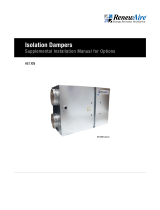
SPECIFICATIONS & DIMENSIONS
4 1/8" Typ.
4 1/8" Typ.
10 3/8" Typ.
1 3/4"
SA
RA
OA
EA
Power Outlet Box
7/8" Knockouts
Pressure Ports
(4) Typ.
9 1/2"
Overall
7 5/8" Minimum
Service Area
(Door can be
removed from
hinges.)
18 3/4"
19 7/8" Minimum
Service Area
2 1/8"
Minimum
Latch
Clearance
21 1/4" Overall
(With Hanging Brackets)
9 1/8"
Case
Door
Swing
2" Typ.
26 3/4" Case
4 1/4" Typ.
30 3/4" Overall
19" Case
6" Nominal Typ.
8" Nominal Typ.
22 1/4"- 23 1/4" Overall
With Ceiling Brackets
20 3/8" Overall
Control
Terminals
LEFT VIEW
(Hard Mount Depicted) FRONT VIEW
RIGHT VIEW
(Hanging Mount Depicted)
TOP VIEW
Model: SL75H
Drawing Type: Unit Dimension
Version: MAY22
ABBREVIATIONS
EA: Exhaust Air to outside
OA: Outside Air intake
RA: Room Air to be exhausted
SA: Supply Air to inside
INSTALLATION ORIENTATION
Unit may be installed in any
orientation.
NOTE
1.UNLESS OTHERWISE SPECIFIED,
DIMENSIONS ARE ROUNDED TO THE
NEAREST EIGHTH OF AN INCH.
2.SPECIFICATIONS MAY BE SUBJECT
TO CHANGE WITHOUT NOTICE.
AIRFLOW ORIENTATION
Available as shown in dimension drawing.
UNIT MOUNTING & APPLICATION
Can be mounted in any orientation. RA/EA
airstream can be switched with OA/SA airstream.
SL75H Energy Recovery Ventilator EC Motor

1.800.627.44998
S L- S e ri es
ERV
1.0 OVERVIEW 10
1.1 DESCRIPTION .......................................................10
1.2 OPERATING MODES ..............................................10
1.3 UNIT WEIGHTS ......................................................11
2.0 COMPONENT DESCRIPTION 11
2.1 CABINET ..............................................................11
2.1.1 Removable Door with Interlock Switch ............................... 11
2.2 FANS ....................................................................11
2.3 CONTROLLER .......................................................11
2.3.1 Controller Power Supply .................................................... 11
2.4 DUCTS .................................................................12
2.5 ENTHALPIC CORE .................................................14
2.6 FILTERS ...............................................................14
2.7 CONTROLS TERMINAL STRIP ................................14
3.0 UNIT PLACEMENT ...................................15
3.1 MOUNTING THE UNIT ............................................15
3.1.1 Horizontal Installation Between Wood Joists ...................... 15
3.1.2 Horizontal Installation Hanging From Chains ...................... 15
3.1.3 Vertical Installation on a Wall or Panel ............................... 16
3.2 SERVICE CLEARANCES .........................................16
3.3 AC POWER SOURCE ..............................................16
3.3.1 Model SL75 ...................................................................... 16
3.3.2 Model SL75H .................................................................... 16
3.4 LOAD BEARING CAPACITY OF SUPPORTS ..............16
4.0 INSTALLATION 17
4.1 USER-SUPPLIED INSTALLATION MATERIALS .......... 17
4.2 VERIFY INSTALLATION REQUIREMENTS .................17
4.3 L-BRACKET INSTALLATION ...................................18
4.4 CHAIN INSTALLATION ...........................................19
4.5 WALL BRACKET INSTALLATION .............................19
4.6 FACTORY-RECOMMENDED ELECTRIC
SERVICE ENTRY .................................................... 21
4.6.1 Model SL75 ......................................................................21
4.6.2 Model SL75H .................................................................... 21
4.7 FACTORY-RECOMENNDED LOW-VOLTAGE
SERVICE ENTRY .................................................... 21
4.8 ATTACHING DUCTS ...............................................21
4.9 SELECTING AIRFLOW SETTINGS ............................ 21
4.10 BALANCING AIRFLOWS .......................................21
4.11 WIRING SCHEMATICS ..........................................23
4.12 LOW-VOLTAGE WIRING DIAGRAMS ......................25
4.12.1 Single Speed Mode CONTINUOUS ....................................25
4.12.2 Low Speed CONTINUOUS/High Speed SWITCHED......................... 25
5.0 OPERATION 26
5.1 MANOMETER READINGS AT COMMISSIONING .......26
5.2 AIRFLOW READINGS AT COMMISSIONING ..............26
5.2.1 Conversion of Pressure Drop to Airflow .............................26
5.2.2 Continuous Mode (low speed) ...........................................26
5.2.3 Boost Mode (high speed) ..................................................26
6.0 MAINTENANCE 27
6.1 MAINTENANCE AFTER 30 DAYS OPERATION ..........27
6.2 RECALIBRATION OF AIRFLOWS .............................27
6.3 DOOR REMOVAL ...................................................27
6.4 SERVICE PARTS .................................................... 28
7.0 TROUBLESHOOTING 29
7.1 INDICATION OF PROBLEM .....................................29
7.2 ERV HAS AIRFLOW BUT IS MAKING NOISE .............29
7.3 NO APPARENT AIRFLOW FROM THE ERV ...............29
7.4 INADEQUATE OR REDUCED AIRFLOW
FROM THE ERV ..................................................... 30
7.5 ERV FAILS TO RUN IN EITHER LOW SPEED
OR HIGH SPEED .................................................... 30
7.6 NO APPARENT REASON FOR LOW AIRFLOW ..........30
8.0 FACTORY ASSISTANCE ...........................31
TABLE OF CONTENTS

91.800.627.4499
S L- S e ri es ERV
Figure 1.2.0 SL75/H Cutaway View ............................................ 10
Figure 2.1.0 Pressure Port Locations .......................................... 11
Figure 2.4.0 Airstream Illustration .............................................. 12
Figure 2.4.1 Separate Return Air Pick-up—Supply Air to Furnace
Return Air Trunk ..................................................... 13
Figure 2.4.2 Separate Return Air and Supply Air ......................... 13
Figure 2.4.3 Furnace Return Air back into Return Air .................. 13
Figure 2.4.4 Furnace Return Air back into Supply Air .................. 13
Figure 2.6.0 SL75/H Filter Locations .......................................... 14
Figure 2.7.0 Controls Terminal Strip. .......................................... 14
Figure 3.1.0 Recommended Horizontal Mounting Options ............ 15
Figure 3.1.1 Optional Vertical Mounting Option ........................... 16
Figure 4.4.0 Support Chain Installation ...................................... 19
Figure 4.5.0 Vertical Installation ................................................20
Figure 4.10.0 Pressure Port Locations ........................................ 22
Figure 4.10.1 Fan Speed Control Potentiometers .........................22
Figure 4.11.0 SL75 Wiring Schematic .........................................23
Figure 4.11.1 SL75H Wiring Schematic ....................................... 24
Figure 4.12.0 Low-Voltage Wiring Diagram 1 ..............................25
Figure 5.2.0 Pressure Drop to Airflow Conversions .....................26
Figure 6.4.0 SL75/H Service Parts .............................................28
TABLE OF CONTENTS
TABLE OF ILLUSTRATIONS

1.800.627.449910
S L- S e ri es
ERV
1.0 OVERVIEW
1.1 DESCRIPTION
1.2 OPERATING MODES
The SL75 & SL75H ERVs are multi-speed air-to-air energy recovery ventilators that are designed
for residential application and have multiple installation options. They can be installed between
joists that are spaced a minimum of 24" on center, they can be suspended from chains, or they
can be mounted on a wall or other object. Each type of installation can be accomplished by a
single person. The SL75 and SL75H are identical except for the method of wiring the power
source to the unit. The SL75 has an integral line cord, ready to be plugged into a standard
120VAC receptacle, while the SL75H is to be hard-wired by the installer.
The ERV exhausts stale Return Air (RA) while transferring both latent and sensible energy
between an incoming fresh outdoor airstream (OA). Energy recovery is accomplished by a static
plate heat exchanger core. Each airstream has a 120V EC fan, which provides airflow from 30 to
130 CFM.
The airflow rate can be changed from Continuous to Boost at any time, using many different
optional sensors or control devices.
The unit may operate with balanced or unbalanced airflow. However, balanced airflow provides
the best energy recovery. Airflow can be adjusted using the motor potentiometers and the
values read via the door pressure taps.
The hinged door has an opening for viewing and access to the potentiometers. The entire
cabinet is lined with foil-backed 1" thick foam insulation.
OVERVIEW
NOTE: This unit is
an Energy Recovery
Ventilator, or ERV.
It is commonly referred to
throughout this manual as
an ERV.
NOTE: Sensible
energy is often
referred to as
“heat energy.”
NOTE: Latent
energy is often
referred to as
“moisture energy.”
The SL75 & SL75H have two different operating modes: Continuous and Boost. Continuous
mode should be set to provide the minimum ventilation requirement. Boost mode can be used to
supply and exhaust a greater volume of air, up to 130 CFM.
The two operating modes are selectable and controlled independently so that different
controlling methods can be used to switch back and forth. Example: an IAQ sensor could be
used to switch the unit to Boost mode.
FIGURE 1.2.0 SL75/H CUTAWAY VIEW
RETURN AIR
DUCT
SUPPLY AIR
DUCT
ENTHALPIC
CORE
EXHAUST AIR
DUCT
OUTSIDE AIR
DUCT
ELECTRICAL BOX
AIR FILTERS
INTERLOCK
SWITCH
SUPPLY AIR
FAN
EXHAUST AIR
FAN

111.800.627.4499
S L- S e ri es ERV
2.0 COMPONENT DESCRIPTION
2.1 CABINET
2.2 FANS
2.3 CONTROLLER
The cabinet is built of 22 gauge (0.64 mm) galvanized steel and is painted white. It has a
hinged, removable door. The exterior of the unit boasts four air pressure test ports, one low-
voltage terminal strip, an access/viewing port, and locations for four duct connectors, (6" or 8",
shipped loose).
2.1.1 Removable Door with Interlock Switch
The insulated access door is hinged on one side and has two securing latches on the other side.
The hinges are separable to allow for removal of the access door for servicing. The door has an
access/viewing port built in to permit adjustment of the fan potentiometers. Directly behind the
access door is a pressure-sensitive interlock switch that will shut off power to the unit if the
door is opened during operation. Also installed on the door are four air pressure test ports, used
for connecting a manometer and taking air pressure measurements.
The SL75 & SL75H have two advanced, high efficiency electronically commutated (EC) 120VDC
variable speed fans. One fan is used for intake air (Outdoor Air/Supply Air) and the other fan
is for the exhaust airstream (Return Air/Exhaust Air). The speed of each fan is controlled
independently by a 0–10VDC signal from the controller.
The controller provides the signal to the EC motors using integral potentiometers. Incoming line
voltage powers both fans and also a step-down Class II transformer which provides 24VAC to
the externally-mounted low-voltage terminal strips. The controller has four potentiometers that
are adjusted by the user to establish fan speeds for each operation mode.
2.3.1 Controller Power Supply
Each SL75 & SL75H have one terminal strip mounted on the end of the unit. The terminal strip
is a 24VAC power supply terminal. The unit control board provides up to 6VA (approximately
0.25A) which can be used to power the various optional control accessories.
1.3 UNIT WEIGHTS
The hanging weight of each SL75/H is approximately 35 pounds.
The shipping weight of each SL75/H is approximately 41 pounds.
COMPONENT DESCRIPTION
FIGURE 2.1.0 PRESSURE PORT LOCATIONS
AIR PRESSURE
TEST PORTS (4)
DUCT CONNECTORS (4)
SEPARABLE HINGES (2)
ACCESS/VIEWING PORT

1.800.627.449912
S L- S e ri es
ERV
2.4 DUCTS
SL75 & SL75H units are supplied with a set of 4 duct connectors that must be field-installed.
The connectors can be used for either 6" round or 8" round ducts. It is preferable to keep duct
runs short and straight to maximize performance.
For all installations, SMACNA guidelines for duct installation should be followed. The most
commonly-used ducting is 6" diameter flexible due to ease of installation, sound attenuation,
and cost, however, rigid ducting is preferred because there is less resistance to airflow,
resulting in less power consumption to deliver the same amount of air.
A total of four duct runs will generally be used:
u One duct will provide clean outdoor air (Outside Air) to the SL75/H. This duct will normally be
capped by an air inlet cap mounted on the exterior side wall of a residence and equipped with
a bird screen.
Wall intakes must be located at least 10' from any appliance vent or any vent opening from
a plumbing drainage system. Wall intakes must also be 10' from any exhaust fan discharge
outlet unless that outlet is 3' or more above the intake location. (IRC 2006, Section M1602.2)
u One duct will be needed to exhaust stale air (Exhaust Air) to the outdoors. This duct will
normally end at an exhaust cap located on an exterior wall of a residence.
u One duct will be needed to deliver fresh, conditioned air (Supply Air) from the SL75/H to a
desired location in the residence. The Supply Air duct may end in a floor or wall grate with
an area of at least 28 square inches. Alternatively, the Supply Air duct may be connected
directly into the return air duct or the supply air duct for the main heating and cooling system.
When connecting to the main return air duct, it must be at least 3' from the return plenum to
minimize suction from the furnace blower.
u One duct is used to collect indoor air (Return Air), running from return grilles through the
energy exchange core in the SL75/H before being exhausted to the outdoors.
If the SL75/H is located in a conditioned space, only the OA and EA ducts need to be insulated.
If it is installed in an unconditioned space such as an attic or crawl space, the SA, OA, RA, and
EA ducts must be insulated.
COMPONENT DESCRIPTION
NOTE: Ducts inside a
building that are con-
nected to the outside
must be insulated with a
sealed vapor barrier on both
the inside and the outside of
the insulation.
FIGURE 2.4.0 AIRSTREAM ILLUSTRATION
EXHAUST AIR
(TO OUTDOORS)
SUPPLY AIR
(TO OCCUPIED SPACE)
RETURN AIR
(FROM OCCUPIED SPACE)
OUTSIDE AIR
(INTO UNIT)
IMPORTANT
It is important to understand and use the equipment airstream terminology as it is used in
this manual. The airstreams are defined as:
u Outside Air (OA): Air taken from the external atmosphere and, therefore, not previously
circulated through the system.
u Supply Air (SA): Air that is downstream of the enthalpic core and is either supplied to the
occupied space or to an additional conditioner.
u Conditioned Air (CA): Air that is supplied to an occupied space.
u Return Air (RA): Air that is returned to a heating or cooling appliance from a conditioned
space.
u Exhaust Air (EA): Air that is removed from a heating or cooling appliance and discharged.
NOTE: If you wish to
install the unit in an
attic or other uncon-
ditioned space, you must
insulate all of the unit’s
ductwork that is located in
the attic. Use at least R-6
insulation.

131.800.627.4499
S L- S e ri es ERV
COMPONENT DESCRIPTION
NOTE: For the setup
in Figure 2.4.3, the
furnace blower must
be operated any
time the ERV is operat-
ed. Use furnace fan “on”
continuous low speed or
optional FM control to
cycle furnace fan on ERV.
FIGURE 2.4.3 FURNACE RETURN AIR BACK INTO RETURN AIR
NOTE: ERV blower
may be operated
separate from fur-
nace blower.
FIGURE 2.4.1 SEPARATE RETURN AIR PICK-UP—SUPPLY AIR TO FURNACE RETURN AIR TRUNK
NOTE: ERV blower
may be operated
independently from
furnace blower.
Use caution to introduce FA
at low velocity and where
good mixing will occur to
minimize discomfort
from drafts
FIGURE 2.4.2 SEPARATE RETURN AIR AND SUPPLY AIR
NOTE: ERV blower
may be operated
separate from fur-
nace blower.
FIGURE 2.4.4 FURNACE RETURN AIR BACK INTO SUPPLY AIR

1.800.627.449914
S L- S e ri es
ERV
UNIT PLACEMENTUNIT PLACEMENT
2.7 CONTROLS TERMINAL STRIP
A single terminal strip is located at the end of each SL75 & SL75H, providing a 24VAC
connection to Boost mode or to control accessories. For detailed information, see the Low-
Voltage Wiring Diagrams in Section 4.11 of this manual.
FIGURE 2.7.0 CONTROLS TERMINAL STRIP
24VAC COMMON
HIGH SPEED (BOOST) MODE
120VAC LINE CORD (SL75 ONLY)
2.5 ENTHALPIC CORE
Each SL75 & SL75H has a static-plate, cross-flow core separates the outgoing, polluted
indoor airstream from the incoming supply airstream—while simultaneously transferring total
energy (heat and water vapor) between the two. Airstreams do not mix, and pollutants are not
transferred across partition plates.
NOTE: The cores
used in all ERVs are
static plate enthalpic
cores. They are commonly
referred to in this manual
as “cores.” 2.6 FILTERS
Each SL75 & SL75H is equipped at the factory with mesh-type anti-microbial MERV 8 filters on
both the OA and RA sides of the core. If desired, the mesh-type OA filter can be replaced with
an optional MERV 13 pleated paper filter accessory, which will ship loose.
FIGURE 2.6.0 SL75/H FILTER LOCATIONS
OA FILTER (FILTERS THE INCOMING
OUTDOOR AIR FOR USE IN THE OCCUPIED
SPACE AND ALSO PROTECTS THE CORE).
THIS FILTER CAN BE REPLACED WITH A
PLEATED PAPER MERV 13 FILTER.
RA FILTER (PROTECTS THE CORE
FROM DUST AND DIRT BEING
CARRIED BY THE
RETURN AIRSTREAM)

151.800.627.4499
S L- S e ri es ERV
UNIT PLACEMENT
Risk of injury when lifting
unit and installing
it overhead.
CAUTION
3.1 INSTALLATION HARDWARE
3.0 UNIT PLACEMENT
RenewAire recommends installation of the SL75 & SL75H by a professional HVAC installer with
knowledge of local building codes who is able to properly balance the airstreams prior to use.
The SL75 & SL75H can be installed by one person.
A variety of installation hardware is shipped with each unit, providing for mounting between
wood joists, hanging from owner-supplied and installed chains with vibration isolation springs
or mounting on a vertical surface, such as a wall or other support panel.
Supplied with all units:
u Four duct collars, to be field-installed on the SL75/H with factory-provided sheet metal
screws.
u One package of sheet metal screws for installation of the duct collars. The enclosed washers
are not needed for this application.
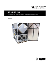
3.1.1 Horizontal Installation Between Wood Joists
Supplied with all units:
u Two long L-Brackets and two short L-Brackets, to be field-installed on the SL75/H.
For horizontal installation between wood structural members (joists) only. The short L-brackets
are used on the hinge side of the unit, the long L-brackets are used on the latch side. The
installer must provide thread-lock, one drop per machine screw, and must provide four 1-1/4
#10 pan head screws for anchoring the brackets to wood joists. The minimum distance between
joists is 22" and the maximum distance is 23".
3.1.2 Horizontal Installation Hanging From Chains
Supplied with all units:
u Four Chain Support Brackets and four vibration isolation springs, to be field-installed on the
SL75/H.
Chain support brackets are field-installed on each corner of the SL75/H with two of the factory-
supplied machine screws per bracket. Installer must provide thread-lock, one drop per machine
screw. Installer must provide chain with a minimum load-bearing rating of 90 pounds and all
anchoring/connecting hardware. Supporting chains are to be angled outward from the brackets
to the anchor points to reduce sway. Vibration Isolation Springs are to be installed on each of
the four installed support chains as shown in Section 4.4 of this manual. Support chains are
attached to the chain support brackets by S-hooks supplied by others, and then crimped shut.
0_D08
RenewAire LLC
SCALE:1:12
SIZE
DWG. NO.
A
MATERIAL:
FINISH:
SEE BILL OF MATERIAL
DO NOT SCALE DRAWING.
REMOVE ALL BURRS, BREAK
SHARP EDGES.
APPLICABLE STANDARDS: DIM.
AND TOL. ANSI Y14.5
UNLESS OTHERWISE SPECIFIED,
DIMENSIONS ARE IN INCHES.
TOLERANCES:
LINEAR
0.015
HOLE SIZE
0.005
ANGULARITY
3
SURFACE FINISH =
63 MICROINCH MINIMUM
DATE:
DRAWN BY:
CRF
6/20/18
160010_000
SHEET 1 OF 4
201 Raemisch Rd.
Waunakee, WI 53597 USA
TEL: (608) 221-4499
FAX: (608) 221-2824
TOLL FREE: (800) 627-4499
TITLE:
CHECKED BY:
DATE:
-- --
SL130L
LEVEL
DESCRIPTION OF REVISION
DATE
BY
---
-
-
SEE BILL OF MATERIAL
FLOOR
JOISTS
SUB-FLOOR
RenewAire LLC
SCALE:1:12
SIZE
DWG. NO.
A
MATERIAL:
FINISH:
SEE BILL OF MATERIAL
DO NOT SCALE DRAWING.
REMOVE ALL BURRS, BREAK
SHARP EDGES.
APPLICABLE STANDARDS: DIM.
AND TOL. ANSI Y14.5
UNLESS OTHERWISE SPECIFIED,
DIMENSIONS ARE IN INCHES.
TOLERANCES:
LINEAR
0.015
HOLE SIZE
0.005
ANGULARITY
3
SURFACE FINISH =
63 MICROINCH MINIMUM
DATE:
DRAWN BY:
CRF
6/20/18
160010_000
SHEET 2 OF 4
201 Raemisch Rd.
Waunakee, WI 53597 USA
TEL: (608) 221-4499
FAX: (608) 221-2824
TOLL FREE: (800) 627-4499
TITLE:
CHECKED BY:
DATE:
-- --
SL130L
LEVEL
DESCRIPTION OF REVISION
DATE
BY
---
-
-
SEE BILL OF MATERIAL
(4) USER-SUPPLIED SUPPORT CHAINS
(SPLAYED OUTWARD FOR STABILITY)
FIGURE 3.1.0 RECOMMENDED HORIZONTAL MOUNTING OPTIONS
NOTE: If you wish to
install the unit in an
attic or other
unconditioned space, you
must insulate all of the
unit’s ductwork that is
located in the attic. Use at
least R-6 insulation.

1.800.627.449916
S L- S e ri es
ERV
3.2 SERVICE CLEARANCES
Primary consideration is sufficient space to open door latches and for the door to be able to
swing open at least 90°. See the dimensioned drawing in the front of this manual for required
clearances.
RenewAire LLC
SCALE:1:12
SIZE
DWG. NO.
A
MATERIAL:
FINISH:
SEE BILL OF MATERIAL
DO NOT SCALE DRAWING.
REMOVE ALL BURRS, BREAK
SHARP EDGES.
APPLICABLE STANDARDS: DIM.
AND TOL. ANSI Y14.5
UNLESS OTHERWISE SPECIFIED,
DIMENSIONS ARE IN INCHES.
TOLERANCES:
LINEAR
0.015
HOLE SIZE
0.005
ANGULARITY
3
SURFACE FINISH =
63 MICROINCH MINIMUM
DATE:
DRAWN BY:
CRF
6/20/18
160010_000
SHEET 3 OF 4
201 Raemisch Rd.
Waunakee, WI 53597 USA
TEL: (608) 221-4499
FAX: (608) 221-2824
TOLL FREE: (800) 627-4499
TITLE:
CHECKED BY:
DATE:
-- --
SL130L
LEVEL
DESCRIPTION OF REVISION
DATE
BY
---
-
-
SEE BILL OF MATERIAL
3.1.3 Vertical Installation on a Wall or Panel
Optional Vertical Installation Kit:
For vertical installation on stud walls or user-supplied support/backing panels. The installer
must provide eight #10 x 2" coarse thread pan head sheet metal screws for installation in wood
studs, two screws per stud per bracket. Installer to provide #10 fine thread pan head screws for
installation into steel studs. When mounted on field-supplied plywood panel, the panel should
be a minimum of 3/4" thick. Mounting screws should be #12 x 3/4" pan head. Factory-provided
mounting screw holes will have to be enlarged.
FIGURE 3.1.1 OPTIONAL VERTICAL MOUNTING OPTION
UNIT PLACEMENTUNIT PLACEMENT
3.3 AC POWER SOURCE
3.3.1 Model SL75
Power requirements: 120VAC, 3.0 amps
The SL75 has an integral 34" long power supply cord. The installer must provide a standard,
grounded 120VAC outlet in the proximity of the ERV. Check all local codes.
3.3.2 Model SL75H
Power requirements: 120VAC, 3.0 amps
The SL75H must be hard-wired by the installer. Check all locals codes before wiring. A
disconnect switch on the AC supply line may be required.
3.4 LOAD BEARING CAPACITY OF SUPPORTS
The SL75 & SL75H ERVs are to be installed by attachment to building structural members such
as joists, bar joists, beams, wall studs, and columns. It is not be supported by attachment to
fixtures such as ductwork or air handlers unless the fixtures are permanently installed and
capable of providing adequate support. Whenever an ERV is installed on or supported by a
fixture, the installation must be approved by a design engineer.

171.800.627.4499
S L- S e ri es ERV
INSTALLATION
4.0 INSTALLATION
4.1 USER-SUPPLIED INSTALLATION MATERIALS
RISK OF INJURY FROM FALLING OBJECTS
Installation of this unit requires hoisting hardware overhead and working directly beneath
heavy objects during the installation process. Observe all OSHA-approved work practices.
Always wear OSHA-approved Personal Protective Equipment (PPE).
CAUTION
RenewAire suggests the use of a duct hoist for hoisting the SL75 & SL75H into position.
For all installations:
u Medium-strength thread-lock,
u UL-181—rated mastic for duct connections,
u Common hand tools such as pliers, drill, screwdriver bits, stud finder, etc.
For wall bracket installations between wood joists:
u Four #10 x 1-1/4" coarse thread sheet metal screws
For chain-suspended installations:
u Chain with a 90 pound load rating,
u Anchoring hardware as needed,
u Attaching hardware such as “S” hooks to connect the chains to the unit support brackets.
For wall bracket installations:
u 24" level,
u Framing square (optional),
u 8 screws for attaching the brackets to the studs or to a plywood panel.
NOTE: Wall brackets
must be supported
by two wall studs.
If the desired location
of the SL75/H does not
permit support by two wall
studs, the SL75/H must be
mounted on a user-sup-
plied 3/4" thick plywood
panel that is anchored on
two wall studs.
NOTE: Hex head
sheet metal screws
may be substituted
for pan head sheet
metal screws.
4.2 VERIFY INSTALLATION REQUIREMENTS
Verify required clearances, availability of 120VAC, access to motor potentiometers, visibility of
LEDs, clearances for ductwork and length of ductwork. See Section 3.0 of this manual.

1.800.627.449918
S L- S e ri es
ERV
INSTALLATION
4.3 L-BRACKET INSTALLATION
User-supplied materials required:
u 1-1/4" x #10 coarse thread pan head sheet metal screws (4)
u Thread-lock
Installation instructions:
See Section 3.1.1 Horizontal Installation Between Wood Joists
u Install the four duct collars on the ends of the SL75/H, using the sheet metal screws
provided.
u Loosely install the four L-brackets on the SL75/H using the factory-provided 1/4–20 machine
screws. Apply a drop of thread-lock to each screw as it is installed. The L-brackets should be
positioned toward the center of the SL75/H, providing clearance for the unit when it is raised
into position.
u Raise the SL75/H into its final location.
u Screw the two brackets on one side to its support joist with user-supplied 1-1/4" #10 coarse
thread sheet metal screws.
u Screw the other two brackets on the other side of the SL75/H to the other support joist.
u Adjust the SL75/H side-to-side, as desired and then tighten all four L-brackets.
Alternate Installation instructions:
An alternate method of installing an SL75/H is to provide temporary support screws in the joists
and then hang the unit on those screws by means of the second set of pre-punched holes in the
L-brackets.
u Install the four duct collars on the SL75/H, using the sheet metal screws provided.
u Loosely install the four L-brackets on the SL75/H using the factory-provided 1/4–20 machine
screws. Apply a drop of thread-lock to each screw as it is installed. The L-brackets should be
positioned toward the center of the SL75/H, providing clearance for the unit when it is raised
into position between the joists.
u From the underside of the joists, identify where the unit is to be located.
u On either side of the joist space the unit will occupy, mark four screw locations, one for each
of the corner L-brackets. Space the marks such that they are 1" or more below the underside
of the sub-floor and 27-1/4" apart. Mark one joist first, then transfer the marks to the second
joist, ensuring that the marks on both joists are aligned.
u Use a scratch awl to start each screw hole and install four 1-1/2" x #10 pan head sheet metal
screws, leaving them about 1/4" out.
u Raise the SL75/H into position and slip the large bracket holes onto the temporary screws.
u Install and tighten four 1-1/4" x #10 coarse thread pan head sheet metal screws through the
smaller holes in the L-brackets.
u Adjust the SL75/H side-to-side as desired. Ensure there is adequate clearance for the door
latches to open and for the door to swing open at least 90 degrees.
u Tighten the eight 1/4–20 machine screws that secure the L-brackets in place.
u Remove the temporary holding screws.
NOTE: When hanging
an SL75/H between
joists, the unit may
be lowered so that it hangs
below the joists. When this
is done, the L-brackets
must still be anchored to
the joists a minimum of
1" above the bottoms of
the joists.
NOTE: When
installing machine
screws into the rivet
nuts on the SL75/H, do not
over-tighten the screws.
The threads in the rivet
nuts can be stripped.
NOTE: These
instructions are
intended for when
a duct hoist is not
available and installation
is being performed by a
single person.

191.800.627.4499
S L- S e ri es ERV
INSTALLATION
4.4 CHAIN INSTALLATION
User-supplied materials required:
u Chain with a minimum load bearing capacity of 90 pounds
u S-hooks for attaching the chains to the SL75/H mounting brackets
u Fastening hardware for attaching the chains to supports
u Thread-lock, medium strength
Installation instructions:
See Section 3.1.2 Horizontal Installation Hanging From Chains
u Install the four duct collars on the SL75/H, using the sheet metal screws provided.
u Attach the four corner brackets to the SL75/H using the factory-supplied 1/4–20 machine
screws. Apply a drop of thread-lock (provided by installer) to each machine screw when it is
installed.
u Install the four support chains from support points. Chains should be located so that they are
splayed slightly outward from the SL75/H, providing sway resistance.
u Install an S-hook on each support chain.
u Raise the SL75/H and slip the S-hooks onto the mounting brackets. Crimp the S-hooks shut.
u Install a Vibration Isolator Spring onto each chain such that it shortens the chain and permits
the springs to support the SL75/H. Correctly installed springs and chains should result in the
springs extending about 1" each.
INSTALL SUPPORT
CHAINS, HANG UNIT
FROM CHAINS
INSTALL VIBRATION
ISOLATOR SPRINGS ON
SUPPORT CHAINS
4.5 WALL BRACKET INSTALLATIONS
User-supplied materials required:
u Thread-lock
u 2" x #10 pan head sheet metal screws (8) if installing directly into wood wall studs
u 3/4" x #12 pan head sheet metal screws (8) if installing on a user-supplied plywood panel
u 3/4" thick plywood for mounting panels if two wall studs can not be spanned
Installation instructions:
See Section 3.1.3 Vertical Installation on a Wall or Panel
u Install the four duct collars on the SL75/H, using the sheet metal screws provided.
u Using a spirit level, draw a level line 26-1/4" long on the wall or the mounting panel. This
represents (approximately) the bottom edge of the SL75/H.
u Draw a second level line exactly 17-1/4" above the first level line.
FIGURE 4.4.0 SUPPORT CHAIN INSTALLATION
NOTE: Wall brackets
are to be supported
by two wall studs,
with two screws per
bracket at each wall stud
location. If the SL75/H
must be positioned such
that the brackets can not
span two wall studs, a
3/4" thick plywood mount-
ing panel that is large
enough to span two wall
studs must be provided
and installed.
NOTE: When
installing machine
screws into the rivet
nuts on the SL75/H, do no
over-tighten the screws.
The threads in the rivet
nuts can be stripped.

1.800.627.449920
S L- S e ri es
ERV
u Place a framing square on the lower level line and extend a plumb line onto both the upper
and the lower lines. This will establish the left-to-right positions of the two wall brackets.
Alternatively, use a spirit level to make a plumb line.
u Carefully install one wall bracket directly ABOVE the lower level line. The wall bracket must
be lined up exactly with the plumb line and must rest precisely above the level line. Pre-drill
the holes into the wall studs to prevent the screws from wandering when they are driven in.
If the bracket is being anchored directly into wood wall studs, use two 2" x #10 coarse thread
pan head sheet metal screws per bracket per stud.
If the bracket is being anchored on metal studs, use two 2" x #10 fine thread pan head sheet
metal screws per bracket per stud.
u If the bracket is being mounted on a plywood mounting panel, use two 3/4" x #12
coarse thread pan head sheet metal screws per bracket, with two screws at each end
of the bracket.
u If #12 screws are being used, the pre-punched holes in the brackets will have to
be enlarged.
u Carefully align and install the second wall bracket above the upper line.
u Using four of the factory-supplied 1/4–20 machine screws, place a grommet on each screw
and install the screws in the rivet nuts as shown in Figure 4.5.0. Apply a drop of thread-lock
on each screw and leave the screws loose, to help in aligning and installing the unit on the
two brackets.
u Raise the SL75/H into position and slide the grommets into the hooked part of each
bracket end.
u Tug the SL75/H away from the wall to seat the grommets in the brackets and then tighten all
four of the machine screws. Do not over-tighten.
RISK OF ELECTRIC SHOCK OR EQUIPMENT DAMAGE
Whenever electrical wiring is connected, disconnected or changed, the power supply to the ERV
and its controls must be disconnected. Lock and tag the disconnect switch or circuit breaker to
prevent accidental reconnection of electric power.
CAUTION
RenewAire LLC
SCALE:1:12
SIZE
DWG. NO.
A
MATERIAL:
FINISH:
SEE BILL OF MATERIAL
DO NOT SCALE DRAWING.
REMOVE ALL BURRS, BREAK
SHARP EDGES.
APPLICABLE STANDARDS: DIM.
AND TOL. ANSI Y14.5
UNLESS OTHERWISE SPECIFIED,
DIMENSIONS ARE IN INCHES.
TOLERANCES:
LINEAR
0.015
HOLE SIZE
0.005
ANGULARITY
3
SURFACE FINISH =
63 MICROINCH MINIMUM
DATE:
DRAWN BY:
CRF
6/20/18
160010_000
SHEET 3 OF 4
201 Raemisch Rd.
Waunakee, WI 53597 USA
TEL: (608) 221-4499
FAX: (608) 221-2824
TOLL FREE: (800) 627-4499
TITLE:
CHECKED BY:
DATE:
-- --
SL130L
LEVEL
DESCRIPTION OF REVISION
DATE
BY
---
-
-
SEE BILL OF MATERIAL
Use the UPPER
Rivet Nut
for Each
Machine Screw
FIGURE 4.5.0 VERTICAL INSTALLATION
NOTE: When
installing machine
screws into the rivet
nuts on the SL75/H, do not
over-tighten the screws.
The threads in the rivet
nuts can be stripped.
/