Raycus XZ Series High Power
Continuous Wave Fiber Laser User
Guide
Applicable:
RFL-C3000XZ RFL-C4000XZ RFL-C6000XZ
RFL-C8000XZ
RFL-C10000XZ
RFL-C12000XZ
Wuhan Raycus Fiber Laser Technologies Co.,
Ltd.
Vol. 2.5

Wuhan Raycus Fiber Laser Technologies Co., Ltd.
User Guide of RFL-C3000XZ~RFL-C12000XZ
CONTENT
1 SAFETY INFORMATION................................................................................................................................................... 1
1.1 SECURITY LABEL........................................................................................................................................................ 2
1.2 LASER SAFETY GRADE..................................................................................................................................................... 2
1.3 OPTICAL SAFETY.............................................................................................................................................................. 3
1.4 ELECTRICAL SAFETY........................................................................................................................................................ 3
1.5 OTHER SAFETY GUIDELINES............................................................................................................................................ 4
2 PRODUCT DESCRIPTION.................................................................................................................................................5
2.1 FEATURES.........................................................................................................................................................................5
2.2 PACKAGE PARTS...............................................................................................................................................................5
2.3 UNPACKING AND INSPECTION.......................................................................................................................................... 5
2.4 OPERATION ENVIRONMENT.............................................................................................................................................. 6
2.5 ATTENTIONS..................................................................................................................................................................... 6
2.6 SPECIFICATIONS................................................................................................................................................................7
3 INSTALLATION................................................................................................................................................................... 9
3.1 DIMENSIONS..................................................................................................................................................................... 9
3.2 INSTALLATION REQUIREMENTS...................................................................................................................................... 13
3.3 COOLING REQUIREMENTS...............................................................................................................................................15
3.3.1 Requirements for Cooling Water:.......................................................................................................................... 15
3.3.2 Requirements for Delivery Cable Cooling System:............................................................................................... 15
3.3.3 Other Requirements:..............................................................................................................................................16
4 USING THE PRODUCT.....................................................................................................................................................17
4.1 FRONT PANEL.................................................................................................................................................................17
4.1.1 REM/OFF/ON (Key Switch).................................................................................................................................. 17
4.1.2 POWER Indicator (White)..................................................................................................................................... 17
4.1.3 LASER Button/Indicator (Green)...........................................................................................................................17
4.1.4 ALARM Indicator...................................................................................................................................................18
4.1.5 EMERGENCY STOP Button..................................................................................................................................18
4.1.6 Status Lamp............................................................................................................................................................18
4.2 REAR PANEL...................................................................................................................................................................18
4.2.1 AC Input.................................................................................................................................................................18
4.2.2 INTERFACES.........................................................................................................................................................18
4.2.3 WATER Inlet/Outlet for Delivery Cable Connector and Laser Source..................................................................18
4.3 POWER CONNECTION......................................................................................................................................................20
4.4 CONTROL INTERFACE DEFINITION.................................................................................................................................. 22
4.4.1 Safety XP2 24 Pin Interface...................................................................................................................................23

Wuhan Raycus Fiber Laser Technologies Co., Ltd.
User Guide of RFL-C3000XZ~RFL-C12000XZ
1) Mode Signal.......................................................................................................................................................................24
2) Passive Laser-Emitting Indication and Main Power-On Indication.................................................................................25
3) Active Light Indicator and Main Power on Indicator....................................................................................................... 25
4) Power On the Remote-Control Board............................................................................................................................... 26
5) Remote Main Power Supply.............................................................................................................................................. 26
6) The Control Board is Powered on And Output..................................................................................................................26
4.4.2 Hardwire XP1........................................................................................................................................................ 26
4.4.3 XP3 RS232 Interface..............................................................................................................................................29
4.4.4 XP4 Analog Interface.............................................................................................................................................29
4.4.5 XP5 Ethernet Interface.......................................................................................................................................... 29
4.5 INTERLOCKING................................................................................................................................................................30
4.6 SCHEMATIC DIAGRAM OF THE LASER ELECTRICAL CIRCUIT.........................................................................................30
4.7 OPERATION START-UPS SEQUENCES...............................................................................................................................31
5 CONTROL MODE SELECTION...................................................................................................................................... 32
5.1 ON MODE...................................................................................................................................................................... 34
5.1.1 AD Mode Enable....................................................................................................................................................34
5.1.2 Emission External Control Enable........................................................................................................................ 34
5.1.3 Guide laser (Red Guide Beam) Control.................................................................................................................34
5.1.4 Programming Mode............................................................................................................................................... 34
5.1.5 AD Mode................................................................................................................................................................ 35
5.2 REM MODE....................................................................................................................................................................35
5.2.1 AD Mode................................................................................................................................................................ 35
5.2.2 External Control.................................................................................................................................................... 35
5.2.3 Guide laser Control............................................................................................................................................... 35
5.2.4 Programming Mode............................................................................................................................................... 35
6 LASER WIRING MODE AND OPERATION STEPS.................................................................................................... 36
6.1 INTERNAL CONTROL IN ON MODE................................................................................................................................. 36
6.2 LASER OPERATING IN EXTERNAL CONTROL MODE....................................................................................................... 37
6.3 INON MODE,THE LASER EMISSION POWER IS EXTERNALLY CONTROLLED BY ANALOG SIGNAL............................... 38
6.4 LASER OPERATING IN PROGRAMMING MODE................................................................................................................39
6.5 SET THE POWER ANALOG QUANTITY IN REM MODE TO CONTROL THE LASER EMISSION........................................... 40
6.6 POWER COMMUNICATION SETTING IN REM MODE....................................................................................................... 41
6.7 PROGRAMMING MODE IN REM MODE.......................................................................................................................... 42
7 RS232 AND INTERNET COMMUNICATION COMMANDS......................................................................................44
7.1 PORT CONFIGURATION................................................................................................................................................... 44
7.2 LASER COMMUNICATION PROTOCOL (ETHERNET PORT & SERIAL PORT)..................................................................... 44
8 RAYCUS LASER CONTROL SYSTEM INSTRUCTIONS............................................................................................49

Wuhan Raycus Fiber Laser Technologies Co., Ltd.
User Guide of RFL-C3000XZ~RFL-C12000XZ
8.1 MAIN INTERFACE OF THE SOFTWARE............................................................................................................................. 49
8.2 MULTI-LASER CONTROL.................................................................................................................................................49
8.2.1 Add/Delete Laser................................................................................................................................................... 50
8.2.2 Delete Laser...........................................................................................................................................................51
8.2.3 Modify Laser IP..................................................................................................................................................... 51
8.3 MAIN WORKING STATUS DISPLAY................................................................................................................................. 52
8.3.1 Laser’s Cumulative Operating Time Display Area................................................................................................ 53
8.3.2 Laser Working Status Display Area....................................................................................................................... 53
8.3.3 Laser Power-up, Mode Selection, Laser Emission Control Area.......................................................................... 54
8.3.4 Programming Mode Test Area............................................................................................................................... 55
8.3.5 Power Slow Rise & Down Parameter Setting Area...............................................................................................56
8.3.6 Laser Emission Parameters Read the Settings Area..............................................................................................57
8.4 LASER PARAMETER DISPLAY AREA................................................................................................................................ 58
8.5 ALARM TYPE DISPLAY AREA..........................................................................................................................................58
8.6 RAYCUS LASER CONTROL SOFTWARE OPERATING MODE SELECTION...........................................................................59
8.7 LANGUAGE..................................................................................................................................................................... 60
8.8 AUTHORIZATION (TIME-LIMITED LOCKING)...................................................................................................................61
8.8.1 Authorization in User Mode.................................................................................................................................. 61
8.8.2 Authorization in Authorization Mode.................................................................................................................... 62
8.9 ABOUT............................................................................................................................................................................63
8.10 XP1 INTERFACE STATUS INDICATION (IN DIAGNOSTIC MODE)..................................................................................... 64
8.11 LOG (IN DIAGNOSTIC MODE)......................................................................................................................................... 65
8.11.1 Download Log........................................................................................................................................................65
8.11.2 Download Record of Historical Fault................................................................................................................... 65
8.11.3 Downloaded File Address......................................................................................................................................66
8.12 MODULE PARAMETERS (IN DIAGNOSTIC MODE)............................................................................................................66
8.13 PROGRAMMING SETTINGS (WAVEFORM EDITING)..........................................................................................................67
8.13.1 View the Number of Wave Bars Inside the Current Laser..................................................................................... 67
8.13.2 Check Waveform Content.......................................................................................................................................68
8.13.3 Empty All Waveforms............................................................................................................................................. 68
8.13.4 Edit Waveform........................................................................................................................................................69
8.13.5 Command Explanations.........................................................................................................................................70
9 WARRANTY, REPAIR AND RETURN............................................................................................................................72
9.1 GENERAL WARRANTY.................................................................................................................................................... 72
9.2 LIMITATIONS OF WARRANTY.......................................................................................................................................... 72
9.3 SERVICE AND REPAIR..................................................................................................................................................... 72

Wuhan Raycus Fiber Laser Technologies Co., Ltd.
User Guide of RFL-C3000XZ~RFL-C12000XZ
Figure List
Figure 1 Dimensions of RFL-C3000XZ/C4000XZ...................................................................................................................... 10
Figure 2 Dimensions of RFL-C6000XZ/8000XZ......................................................................................................................... 11
Figure 3 Dimensions of RFL-C10000XZ/12000XZ.....................................................................................................................12
Figure 4 External dimensions of the RFL-HQBH fiber delivery cable connector........................................................................12
Figure 5 External dimensions of the RFL-QD fiber delivery cable connector............................................................................. 13
Figure 6 Product top lifting rings and bottom level adjustment casters........................................................................................14
Figure 7 Front panel...................................................................................................................................................................... 17
Figure 8 View of RFL-C3000XZ - C12000XZ.............................................................................................................................20
Figure 9 Power cords of different models..................................................................................................................................... 21
Figure 10 Power cord plug and socket.......................................................................................................................................... 21
Figure 11 Control signal connectors............................................................................................................................................. 23
Figure 12 Mod signal schematic diagram..................................................................................................................................... 24
Figure 13 Internal schematic diagram...........................................................................................................................................25
Figure 14 Recommended wiring diagram.....................................................................................................................................25
Figure 15 Internal circuit diagram.................................................................................................................................................25
Figure 16 Recommend wiring diagram.........................................................................................................................................26
Figure 17 Recommended wiring diagram.....................................................................................................................................26
Figure 18 XP2 Remote main power supply wiring diagram.........................................................................................................26
Figure 19 Schematic diagram of the laser electrical circuit.......................................................................................................... 30
Figure 20 Key switch at “ON” position software mode wiring diagram...................................................................................... 36
Figure 21 Wiring diagram of power internal and external control of laser emission by MODE..................................................37
Figure 22 In ON mode, the power and laser emission controlled by analog wiring diagram.......................................................38
Figure 23 Wiring diagram of external control laser emission in programming mode, in ON mode............................................ 39
Figure 24 REM mode power and laser emission are externally controlled wiring diagram.........................................................40
Figure 25 Timing diagram.............................................................................................................................................................41
Figure 26 Wiring diagram of power internal control and laser emission external........................................................................ 41
Figure 27 Wiring diagram of programming mode in REM Mode................................................................................................ 42
Figure 28 Timing diagram.............................................................................................................................................................43
Figure 29 Raycus Laser Control Software displays main interface.............................................................................................. 49
Figure 30 Multi-laser control interface......................................................................................................................................... 50
Figure 31 Communication status interface between rlcs and the laser......................................................................................... 50
Figure 32 Adding the fiber laser....................................................................................................................................................50
Figure 33 Procedure for Adding the IP Address to Laser..............................................................................................................51
Figure 34 Delete laser................................................................................................................................................................... 51
Figure 35 Change the IP address of laser...................................................................................................................................... 51
Figure 36 Modify the IP address of laser...................................................................................................................................... 52
Figure 37 A diagram of the laser's main display area....................................................................................................................52
Figure 38 Laser cumulative operating time display interface....................................................................................................... 53

Wuhan Raycus Fiber Laser Technologies Co., Ltd.
User Guide of RFL-C3000XZ~RFL-C12000XZ
Figure 39 A diagram of the laser's working status display area.................................................................................................... 53
Figure 40 Laser power-on, mode selection, laser emission control display area..........................................................................55
Figure 41 Laser programming mode test area display interface................................................................................................... 55
Figure 42 Slow rise and fall parameter area..................................................................................................................................56
Figure 43 Slow rise and fall setting...............................................................................................................................................56
Figure 44 The power ramping time rise........................................................................................................................................ 56
Figure 45 The power ramping time fall.........................................................................................................................................56
Figure 46 Laser emission parameter setting area display interface.............................................................................................. 57
Figure 47 The output waveform of the laser when the internal pulse duty cycle is 100%........................................................... 57
Figure 48 The output waveform of the laser when the internal pulse duty cycle is less than 100%............................................ 58
Figure 49 Laser parameter display area display interface.............................................................................................................58
Figure 50 Laser alarm type display area interface........................................................................................................................ 59
Figure 51 Laser operating mode selecting.................................................................................................................................... 59
Figure 52 The display area interface of the user mode selecting.................................................................................................. 60
Figure 53 Language selection interface........................................................................................................................................ 60
Figure 54 The authorization settings operating interface in user mode........................................................................................ 61
Figure 55 Authorization settings operating interface in authorization mode................................................................................ 62
Figure 56 Generate authorization code......................................................................................................................................... 63
Figure 57 Lock set successfully.................................................................................................................................................... 63
Figure 58 Laser relevant information query interface...................................................................................................................64
Figure 59 The XP1 interface view................................................................................................................................................ 64
Figure 60 Laser’s working log interface....................................................................................................................................... 65
Figure 61 Log download interface................................................................................................................................................ 65
Figure 62 Historical fault record download interface................................................................................................................... 66
Figure 63 The file address query interface for all downloaded information.................................................................................66
Figure 64 Module parameters query interface in diagnostic mode...............................................................................................67
Figure 65 The programming interface in waveform editing mode............................................................................................... 67
Figure 66 Operating interfaces of wave bar stored inside the current laser.................................................................................. 68
Figure 67 Waveform content interface in the current laser waveform mode................................................................................ 68
Figure 68 Interface of empty all waveform stored in the current laser waveform mode.............................................................. 69
Figure 69 Step 1: Left click the pre-edited waveform number..................................................................................................... 69
Figure 70 Step 2: Select the command under the command type, click “Add”............................................................................69
Figure 71 Step 3: Enter the parameters and click “Save”............................................................................................................. 70
Figure 72 Step 4: After editing all commands, click “Write Laser”............................................................................................. 70
Figure 73 Step 5: New waveform number will turn green when users re-click the “Refresher List”.......................................... 70

Wuhan Raycus Fiber Laser Technologies Co., Ltd.
User Guide of RFL-C3000XZ~RFL-C12000XZ
Table List
Table 1 Operation conditions for the laser...................................................................................................................................... 6
Table 2 Product specifications.........................................................................................................................................................7
Table 3 Water cooling requirements..............................................................................................................................................15
Table 4 Definition and parameter requirements of AC interface.................................................................................................. 22
Table 5 Safety XP2 24 pin interface definition............................................................................................................................. 23
Table 6 XP1 Hardwire interface definition................................................................................................................................... 27
Table 7 XP3 serial interface definitions........................................................................................................................................ 29
Table 8 XP4 analog interface definitions...................................................................................................................................... 29
Table 9 XP5 communication interface definition..........................................................................................................................29
Table 10 Control modes and their subsequent operating methods................................................................................................32
Table 11 Laser protocol contents and command examples........................................................................................................... 44
Table 12 The laser main display content and meanings................................................................................................................52
Table 13 The laser main display area clarification........................................................................................................................53
Table 14 Laser power-on, mode selection, laser emission control display area explanation........................................................55
Table 15 Laser operating mode and explanation...........................................................................................................................59
Table 16 Command explanations in laser working status............................................................................................................. 70

Wuhan Raycus Fiber Laser Technologies Co., Ltd.
User Guide of RFL-C3000XZ~RFL-C12000XZ
1
1 Safety Information
Thank you for choosing Raycus Fiber Laser Products, hereinafter refers as the Product/Products or
Lasers/Laser. This users’ manual provides you with important safety, operation, maintenance, and other
relevant information. Please read the manual carefully before using the product. To ensure safe operation
and optimum product operation, please observe the following cautions and warnings as well as other
information within this manual.

Wuhan Raycus Fiber Laser Technologies Co., Ltd.
User Guide of RFL-C3000XZ~RFL-C12000XZ
2
1.1 SECURITY LABEL
WARNING: May cause serious injury to the person or even endanger
the safety of life.
CAUTION: May cause general injury to the person or damage to
products or equipment.
Englis
h label
Chinese label
English label (12000W as
example)
Chinese label (12000W as example)
English
label
Chinese label
1. Laser Emission Aperture
2.Class 4 Laser Product
3.Class 2M laser Product
– 1 mW Guide laser
4.CE Certification
5.Product Nameplate
(12000W as an example)
6.Laser Radiation Hazard
7. Electrical Hazard
1.2 Laser Safety Grade
According to European Standard EN 60825-1, Clause 9, this series of laser products are Class 4 laser
products. This product emits laser radiation at a wavelength of 1080 nm or around 1080 nm, and the
average laser power of the products listing in this User Guide radiated from the fiber delivery cable is

Wuhan Raycus Fiber Laser Technologies Co., Ltd.
User Guide of RFL-C3000XZ~RFL-C12000XZ
3
ranged from 3000W to 12000W (depending on the product model). Either directly or indirectly being
exposed to high power laser radiation will bring permanent damage to the eye or skin. Even though the
radiant laser is not visible at the wavelength of about 1080nm, the beam will cause irreparable damage to
the retina or cornea, so appropriate and certified laser safety glasses must be worn throughout the laser
emitting.
WARNING: Users must wear appropriate laser goggles when operating
this device. The laser goggles should be selected according to the range
of wavelength emitted from this product. Users must ensure that the
protect range of laser goggles over the entire range of laser wavelengths.
It is forbidden to watch the laser fiber delivery connector during laser
emission.
1.3 Optical Safety
The dust on the end of the fiber delivery connector may bring damage to the lens or the entire laser
device.
CAUTION: DO NOT emit the laser when the black plastic protective
cap is not removed, otherwise the lens or the crystal will be damaged.
1.4 Electrical Safety
1) Ensure that the product is effectively grounded, and the installation environment is safe and reliable.
WARNING: The disconnection of the product grounding will cause the
product shell to become electrified, which may result in personal injury
to the operator.
2) Ensure that the AC voltage is supplied normally.
CAUTION: Wrong wiring mode or power supply voltage will cause an
irrecoverable damage to the laser device.

Wuhan Raycus Fiber Laser Technologies Co., Ltd.
User Guide of RFL-C3000XZ~RFL-C12000XZ
4
1.5 Other Safety Guidelines
1) DO NOT watch the fiber delivery connector of the product directly by anytime when the product is
powered on.
2) DO NOT use the product in a dark or dim place.
3) If the product is used in a manner not specified in this document, the resulted impairment to the laser
will not be covered by the warranty.
4) There are no user serviceable parts, equipment, or assemblies inside the product. All service and
maintenance shall be performed and conducted by the Raycus engineer or authorized personnel. In
order to prevent electric shock, DO NOT break the seal or remove the shell. Failure to comply with
this instruction and the resulted impairment to the laser will not be covered by the warranty.

Wuhan Raycus Fiber Laser Technologies Co., Ltd.
User Guide of RFL-C3000XZ~RFL-C12000XZ
5
2 Product Description
2.1 Features
Fiber lasers are compact and ready to use in comparison with conventional laser products, featuring
higher electrical to optical conversion efficiencies, lower power consumption and better beam quality.
Furthermore, thanks to its flexible laser emission design by using a shielded optical fiber, it can be easily
and safely integrated into a varies of laser application systems.
Main features:
High beam quality;
High reliability;
Maintenance-free operation;
High electrical-optical efficiency;
Convenient control interface;
Fast modulation.
Typical Applications:
Industrial metal cutting and welding;
Scientific research.
2.2 Package Parts
Please refer to the enclosed Package Parts List to cross check what accessories should be contained in the
packing box.
2.3 Unpacking and Inspection
Through the specially designed packaging materials and cabinets, Raycus ensures that the lasers are fully
protected during the transportation. Nevertheless, in order to prevent any unpredictable situation during
transportation, the users still need to carefully check whether the package is correctly handled before
unpacking, and whether there is any damage or suspicious appearance such as collision, crack or water
stain on the outside of the box. Once users find that there is an abnormality in the external cabinet, please
inform Raycus at once.
Please double check if each listed content is inside the package; and contact Raycus as soon as possible if
there is any unusual issue.
Take extra care when removing the product from the package and try to make the fiber delivery cable
with its connector staying away from collision and vibration. Please DO NOT distort, bend, or pull the
delivery cable when unpacking the device; and avoid any collision to the quartz or protective cap of

Wuhan Raycus Fiber Laser Technologies Co., Ltd.
User Guide of RFL-C3000XZ~RFL-C12000XZ
6
laser emission.
CAUTION: The fiber delivery cable and its connector are precise optic
instrument, any vibration or impact to the fiber delivery cable or connector, twist
or excessive bend will damage the product.
2.4 Operation Environment
The required operation conditions are listed as in the Table 1:
Table 1 Operation conditions for the laser
Model
C3000Z
C4000XZ
C6000XZ
C8000XZ
C10000XZ
C12000XZ
Supply Voltage
Three-phase four-wire, AC 323V~AC 437V, 50/60Hz (with PE)
Power Supply Capacity
>15 kVA
> 18 kVA
> 25 kVA
> 35 kVA
> 45 kVA
> 50 kVA
Water Cooling Flow
>35 L/min
> 35 L/min
> 52 L/min
> 64 L/min
> 79 L/min
> 94 L/min
Installation Environment
Flat, no vibration nor impact
Ambient Temperature
10℃~ 40 ℃
Relative Humidity
<70%
1) Make sure the product is properly grounded before use.
2) The fiber delivery cable connector is well connected with the fiber optic cable (delivery cable).
Please inspect the fiber delivery cable connector carefully for dust or other contaminations. Use
appropriate lens cleaning paper to remove the dust before laser emission.
3) Failure to follow the instructions when using the laser may cause malfunction or damage.
4) DO NOT install the fiber delivery cable connector during laser emission.
5) DO NOT watch the fiber delivery cable connector lens directly if the laser is powered on. MUST
wear the appropriate protective goggles all the time when operating the laser.
TIPS:
Install the laser in an air-conditioned environment will offer the product to benefit a longer life and better
performance.
2.5 Attentions
1) Make sure that the mail power supply of AC 380V correctly connected. Wrong connection will
damage the product.

Wuhan Raycus Fiber Laser Technologies Co., Ltd.
User Guide of RFL-C3000XZ~RFL-C12000XZ
7
2) It is important to keep the fiber delivery cable connector clean, otherwise it will damage the product.
3) Please cap the fiber delivery cable connector when it is not in use. DO NOT touch the top lens of the
connector at any time. Use appropriate lens cleaning paper to clean it when any dust or dirt is
noticed.
4) Keep the cap safety in the storage box when using the product. To avoid dust inside the cap that may
pollute the lens of the connector, make sure the opening direction of the cap is put down.
5) Failure to follow those above instructions may cause laser power loss, such loss will not be covered
by warranty.
2.6 Specifications
Table 2 Product specifications
Optical Characteristics
Product
C3000XZ
C4000XZ
C6000XZ
C8000XZ
C10000XZ
C12000XZ
Remark
Emission Power
3 kW
4 kW
6 kW
8 kW
10 kW
12 kW
/
Operation Mode
Continuous Wave / Modulated
/
Polarization
Random
/
Emission Power
Range
10% ~ 100 %
/
Emission
Wavelength
1080 ± 5 nm
Nominal
Emission Power
Emission Power
Instability
≤ ± 1.5 %
Nominal
Emission
Power;
Duration: >5hrs;
Ambient Temp.:
24±1℃
Modulation
Frequency
50~5k Hz
50~2k Hz
Nominal
Emission Power
Red Guide Laser
Power
0.5~1 mW
/
Fiber delivery
cable connector
RFL-HQBH
RFL-QD
/
Beam Quality
(BPP)
≤4 mm •mrad
Nominal
Emission Power
Fiber Core
Diameter
100 μm
Customizable
Fiber Delivery
Cable Length
20 meters
Customizable
Electrical Characteristics
Operating Voltage
Three-phase four-wire system AC 340V ~ 420V, 50/60Hz (with PE)
/

Wuhan Raycus Fiber Laser Technologies Co., Ltd.
User Guide of RFL-C3000XZ~RFL-C12000XZ
8
Max. Power
Consumption
9 kW
11.5 kW
17.5 kW
23 kW
28.5 kW
34.5 kW
/
Way to Control
Serial Communication / AD
/
Other Characteristics
Dimension
W×H×D (mm)
670×990×1160
900×960×1160
1200×960×1160
Includes casters
and rings,
without warning
lights
Weight
< 250 kg
< 280 kg
< 360 kg
< 400 kg
< 450 kg
< 500 kg
Air conditioning
included
Operating
Ambient
Temperature
10 ~ 40 °C
/
Humidity
<70 %
/
Storage
Temperature
-10 ~ 60 °C
/
Cooling Method
Water Cooling
/

Wuhan Raycus Fiber Laser Technologies Co., Ltd.
User Guide of RFL-C3000XZ~RFL-C12000XZ
9
3 Installation
3.1 Dimensions
The mechanical dimensions of RFL-C3000XZ/C4000XZ/C6000XZ/C8000XZ/C10000XZ/ C12000XZ
are shown as follow:
1) The dimensions of the RFL-C3000XZ/C4000XZ are shown in Figure 1 (taking RFL-C4000XZ as an
example).
Figure 1.a - Front and rear view

Wuhan Raycus Fiber Laser Technologies Co., Ltd.
User Guide of RFL-C3000XZ~RFL-C12000XZ
10
Figure 1.b - Top and left side view of the product
Figure 1 Dimensions of RFL-C3000XZ/C4000XZ
Those two models of RFL-C3000XZ and C4000XZ share a same cabinet, henceforth the same
dimensions of 670 ×990 ×1160mm (width ×depth ×height, including casters and rings, excluding the
stats lamps), and the weight is about 250 kg for RFL-C3000XZ, and about 280 kg for RFL-C4000XZ.
2) The dimensions of the RFL-C6000XZ and C8000XZ are shown in Figure 2 (taking RFL-C8000XZ
as an example)
Figure 2.a - Front and rear view

Wuhan Raycus Fiber Laser Technologies Co., Ltd.
User Guide of RFL-C3000XZ~RFL-C12000XZ
11
Figure 2.b -Top and left side view
Figure 2 Dimensions of RFL-C6000XZ/8000XZ
RFL-C6000XZ and C8000XZ share a same cabinet, and henceforth the same dimensions of 900 ×960 ×
1160 mm (width ×depth ×height, casters and rings, excluding alarm lights), and the weight is about 360
kg for RFL-C6000XZ and 400 kg for RFL-C8000XZ.
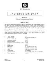
3) dimensions of the RFL-C10000XZ/C12000XZ are shown in Figure 3 (taking RFL-C12000XZ as an
example)
Figure 3.a - Front and rear view

Wuhan Raycus Fiber Laser Technologies Co., Ltd.
User Guide of RFL-C3000XZ~RFL-C12000XZ
12
Figure 3.b - Top and left side view
Figure 3 Dimensions of RFL-C10000XZ/12000XZ
Those two models of RFL-C10000XZ and C12000XZ share a same set of cabinet, and henceforth the
same dimensions of 1200 ×960 ×1160 mm (width ×depth ×height, including casters and rings,
excluding alarm lights); The weight is about 450 kg for RFL-C10000XZ and 500 kg for RFL-C12000XZ.
The type and dimensions of RFL-C3000XZ/C4000XZ/C6000XZ/C8000XZ/C10000XZ/C12000XZ’s
fiber delivery cable and cable connector are as follows:
1) RFL-C3000XZ/C4000XZ/C6000XZ uses the RFL-HQBH model cable connector, and the external
dimensions of the cable connector are shown in Figure 4:
Figure 4 External dimensions of the RFL-HQBH fiber delivery cable connector
2) RFL-C8000XZ/C10000XZ/C12000XZ uses the RFL-QD model cable connector, and the external
dimensions of the output optical cable connector are shown in Figure 5:

Wuhan Raycus Fiber Laser Technologies Co., Ltd.
User Guide of RFL-C3000XZ~RFL-C12000XZ
13
Figure 5 External dimensions of the RFL-QD fiber delivery cable connector
NOTE:
1) The dimensions in the above figures are in the unit of mini-meter (mm).
2) Before the laser is powered on, make sure that the two copper contacts (interlock pins) on the fiber
connector are shorted well, otherwise the laser will not work properly.
3) Before installing the fiber delivery cable connector into the laser processing head, the lens of the fiber
delivery cable must be inspected carefully.
4) If the fiber delivery cable lens is dirty, the lens must be cleaned well. It is forbidden to disassemble
the protective lens by anyone other than staff of Raycus or Raycus authorized personnel, otherwise
the warranty will be invalidated.
3.2 Installation Requirements
1) Place the laser horizontally in a suitable position and fix it as necessary;
2) Before the laser is powered on, check if the power supply has the correct voltage (AC 323V ~ 437V,
50/60Hz, see Table 2 Product Technical Data Sheet for details), and the grounding line (PE) shall
be well grounded all time during powering on;
3) Connect the power cable and control cable to the product when power supply is OFF;
4) Connect the cooling system to the laser and output optical cable connector according to the water
inlet and outlet signs;
5) Please check the laser fiber delivery connector and make sure to clean it before installing it in the
equipment;
6) DO NOT step on, squeeze, or excessively bend the protective tube during the installation of the
output optical cable to avoid damage to the optical fiber;
7) In the process of installing the fiber delivery connector, ensure the cleanliness of the surrounding
environment (DO NOT use electric fans to dissipate heat when it is hot in summer to avoid large
dust in the air);
8) The minimum bending diameter of the laser transmission cable in non-working conditions such as
transportation and storage shall not be less than 20 cm. When the laser is emitting, the minimum
bending diameter shall not be less than 30 cm;
Page is loading ...
Page is loading ...
Page is loading ...
Page is loading ...
Page is loading ...
Page is loading ...
Page is loading ...
Page is loading ...
Page is loading ...
Page is loading ...
Page is loading ...
Page is loading ...
Page is loading ...
Page is loading ...
Page is loading ...
Page is loading ...
Page is loading ...
Page is loading ...
Page is loading ...
Page is loading ...
Page is loading ...
Page is loading ...
Page is loading ...
Page is loading ...
Page is loading ...
Page is loading ...
Page is loading ...
Page is loading ...
Page is loading ...
Page is loading ...
Page is loading ...
Page is loading ...
Page is loading ...
Page is loading ...
Page is loading ...
Page is loading ...
Page is loading ...
Page is loading ...
Page is loading ...
Page is loading ...
Page is loading ...
Page is loading ...
Page is loading ...
Page is loading ...
Page is loading ...
Page is loading ...
Page is loading ...
Page is loading ...
Page is loading ...
Page is loading ...
Page is loading ...
Page is loading ...
Page is loading ...
Page is loading ...
Page is loading ...
Page is loading ...
Page is loading ...
Page is loading ...
Page is loading ...
Page is loading ...
/