Page is loading ...

1
IT-ES2010-IU-2GS
Unmanaged Industrial
Ethernet switch
user manual
【Summarize】
IT-ES2010-IU-2GS is a type of plug-and-play industrial unmanaged redundant Ethernet switch, which supports 8 10/100M ports, and 2 gigabit
Ethernet ports (SFP slots). No fan, low consumption and industrial grade design. More steadily work capability. To satisfy applications in different
industrial environments, IT-ES2010-IU-2GS can also provide wide temperature type in accommodation with limit temperature (-40 ~ 75°C) and we
have got CE, FCC approvals.
【Packing List】
The first time use this product, please check the packaging is intact or not and the attachment is complete or not at first.
IT-ES2010-IU-2GS x1
User manual x1
Certificate x1
Warranty card x1
DIN-rail kit
If you find that the device is damaged or any parts of it is missing during transportation, please notify the Company or the Company’s distributor,
we will give you proper solution as soon as possible.
【Features】
1. Support 8 10/100M ports, and 2 gigabit Ethernet ports (SFP slots)
2. Support IEEE802.3/802.3u /802.3x
3. Support 10/100M, half/full duplex, MDI/MDI-X
4. Support broadcast storm shield
5. DC12~48V Power input
6. Support industrial grade 4 level
7. IP30 protection, metal shell, DIN Rail

2
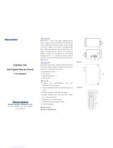
【Panel layout】
IT-ES2010-IU-2GS:
Dimension(mm)
【Power input】
Top view Front view
IT-ES2010-IU-2GS-P(12/48VDC) top panel provided 4 bit industrial terminal block, power input is 24VDC(12~48VDC) , the sign of the terminal
block is V1-, V1+, V2-, V2+, it is redundant power input, both of them are 12~48VDC
IT-ES2010-IU-2GS-P(12/48VDC) DC power input had redundant function, provided PWR1 and PWR2 power input, can use for single, and
can connect 2 separately power supply system, use 1 pair terminal block connect the device at the same time. If one of the power system broke, the

3
device can work un-interruptible, built-in overcorrect protection, Reverse connection protection
Note:1, Power ON: please insert the power cable’s terminal block into device’s power pot at first and then insert the power supply.
2, Power OFF, please pluck the plug of the power supply and then strike the terminal block parts.
【Communication interfaces】
IT-ES2010-IU-2GS provide 8 port 10/100BaseT(X) Ethernet(RJ45) and 2 port gigabit SFP optic fiber.
10/100BaseT(X) Ethernet port
10/100BaseT(X) Ethernet port is in front panel of the device. The connector type is RJ45 and its pin definition is shown below. The pinout of
RJ45 port display as below, connect by UTP or STP. The connect distance is no more than 100m. 100Mbps is used 100Ωof UTP 5 , 10Mbps is
used 100Ωof UTP 3,4,5.
RJ 45 port supports automatic MDI/MDI-X operation. It can connect the PC, Server, Converter and HUB. Corresponding connection of Pin
1,2,3,6 in MDI: 1→1, 2→2, 3→3, 6→6; corresponding connection of pin 1,2,3,6 in MDI-X: 1→3, 2→6, 3→1, 6→2. the definition of Pin in the
table as below.
PIN
MDI
MDI-X
1
TX+
RX+
2
TX-
RX-
3
RX+
TX+
6
RX-
TX-
4, 5, 7, 8
—
—
Note:“TX±” transmit data ±,“RX±” receive data ±,“—” no use。
MDI (straight-through cable)
MDI-X (crossover cable)
1 8

4
1000BaseSFP port (mini-GBIC)
IT-ES2010-IU-2GS-P (12/48VDC)’s 1000BaseSFP port adopted gigabit mini-GBIC optic fiber, can choice different type fiber according to
different transfer distance, fiber port must used for pair, TX port is fiber transmit side, connect to other device’s RX receive side, RX port is fiber
receive side, connect to other device’s TX transmit side. Fiber port support off-line indicator, can effective increase the reliability of network
running。
Suggestion: please make a sign for the optic fiber (Figure as follows: A-A, B-B), easy to use
【LED indicator】
LED indicator in front panel of IT-ES2010-IU-2GS-P (12/48VDC) monitor working status, it is convenience to find the problem, the function of
each LED is described in the table as below.
System status LED
LED
Statue
Description
PWR
(Green)
ON
PWR2 connect and running normal
OFF
Power supply have no connection or
unwonted
Link/ACT
(Green)
ON
Port made effective connection
Blinking
Port is in active statue
OFF
Port did not make
effective connection
【Installation】
Before installation, confirm that the work environment meet the installation require, including the power needs and abundant space. Whether it is
close to the connection equipment and other equipment are prepared or not.
Installation require as below
1. Avoid in the sunshine, keep away from the heat fountainhead or the area where in intense EMI.
2. Examine the cables and plugs that installation requirements.
3. Examine whether the cables be seemly or not (less than 100m) according to reasonable scheme.
4. Screw, nut, tools provide by yourselves.
5. Power need: power inputs (12~48DC)
6. Environment: -40°C to 85°C
Storage Temperature: -40°C to 85°C

5
Relative humidity 10% to 95%
DIN-Rail Installation
In order to use in industrial environments expediently, IT-ES2010-IU-2GS adopt 35mm DIN-Rail installation, the installation steps as fellows: 1.
Examine the DIN-Rail attachment
2. Examine DIN Rail whether be firm and the position be suitability or not.
3. Insert the top of the DIN-Rail into the slot just below the stiff metal spring.
4. The DIN-Rail attachment unit will snap into place as shown below.
Wiring Requirements
Wiring need to meet the following requirements:
It is needed to check whether the type, quantity and specification of cable match the requirement before cable laying;
It is needed to check the cable is damaged or not, factory records and quality assurance booklet before cable laying;
The required cable specification, quantity, direction and laying position need to match construction requirements, and cable length depends
on actual position;
All the cable cannot have break-down and terminal in the middle;
Cables should be straight in the hallways and turning;
Cable should be straight in the groove, and cannot beyond the groove in case of holding back the inlet and outlet holes. Cables should be
banded and fixed when they are out of the groove;
User cable should be separated from the power lines. Cables, power lines and grounding lines cannot be overlapped and mixed when they
are in the same groove road. When cable is too long, it cannot hold down other cable, but structure in the middle of alignment rack;
Pigtail cannot be tied and swerved as less as possible. Swerving radius cannot be too small (small swerving causes terrible loss of link). Its
banding should be moderate, not too tight, and should be separated from other cables;
It should have corresponding simple signal at both sides of the cable for maintaining.
Technology:
Standard: IEEE802.3, IEEE802.3u, IEEE802.3x, IEEE802.3z
Bandwidth: 5.6G
MAC address: 8K
Flow control: IEEE802.3x
Interfaces:
RJ45 Ports: 10/100BaseT(X) auto connection, Full /Half duplex or force work mode, and support MDI/MDI-X connection
Fiber Ports: 1000BaseSX/LX/LHX/ZX (LC)
LED indicator: PWR, 10/100M, Link/ACT, Link1, Link2, Link3, Link4, Link9, Link10

6
Power:
Input power: 24VDC (12~48VDC)
Input type: 4 bits terminal block
Over voltage protection
Environmental
Operating Temperature: -40 to 75°C
Storage Temperature: -45°C to 85°C
Relative Humidity: 10 to 95% (non-condensing)
Mechanical
Shell: IP30 protection, metal case
Installation: DIN Rail mounting
W×H×D: 136mm×52mm×105mm
Weight: 800g
Approvals:
EMI: FCC Part 15, CISPR (EN55022) class A
EMS: EN61000-4-2 (ESD), Level 3
EN61000-4-3 (RS), Level 3
EN61000-4-4 (EFT), Level 3
EN61000-4-5 (Surge), Level 3
EN61000-4-6 (CS), Level 3
EN61000-4-8, Level 5
Shock: IEC 60068-2-27
Free Fall: IEC 60068-2-32
Vibration: IEC 60068-2-6
Warranty: 5 years
Approvals: FCC, CE, RoHS approvals
/