Sperry instruments DSA-1010 Owner's manual
- Category
- Measuring, testing & control
- Type
- Owner's manual

OPERATING INSTRUCTIONS
MODEL DSA-660
:600A AC Only Type
MODEL DSA-1010
:1000A AC/DC Type
DIGISNAP
SNAP-AROUND
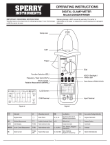
1. Features
Designed to meet international safety standards.
IEC61010-1 & IEC61010-2-032
Measurement Category (CAT.) IV 600V
Pollution Degree 2
Double molded main body provides comfortable
single handed grip
Data Hold Function
LCD Backlight function to facilitate working at dimly lit
situations. (DSA1010 only)
REL function to indicate measurement variation.
(Current, voltage, Resistance measurement)
MIN/MAX function enables easy reading of min & max
value during measurement.
With Continuity & Diode Check Function
NCV (Non Contact Voltage )Function for wiring
check
600V input protection
Sleep function to extend battery life.
With Bar Graph, 6039 count display
2. Safety Warnings
This instrument has been designed, manufactured and
tested according to IEC 61010: Safety requirements for
Electronic Measuring apparatus, and delivered in the
best condition after passed the inspection. This
instruction manual contains warnings and safety rules
which must be observed by the user to ensure safe
operation of the instrument and retain it in safe
condition.
Therefore, read through these operating instructions
before using the instrument.
WARNING
Read through and understand the instructions
contained in this manual before using the
instrument.
Keep the manual at hand to enable quick reference
whenever necessary.
The instrument is to be used only in its intended
applications.
Understand and follow all the safety instructions
contained in the manual.
It is essential that the above instructions are
adhered to.
Failure to follow the above instructions may cause
injury, instrument damage and/or damage to
equipment under test.
The symbol indicated on the instrument means that
the user must refer to the related parts in the manual for
safe operation of the instrument. It is essential to read
the instructions wherever the symbol appears in the
manual.
DANGER is reserved for conditions and
actions that are likely to cause serious or fatal
injury.
WARNING is reserved for conditions and
actions that can cause serious or fatal injury.
CAUTION is reserved for conditions and actions
that can cause injury or instrument damage.
Marks listed in the table below are used on this
instrument.
User must refer to the manual.
Instrument with double or reinforced insulation
Indicates that this instrument can clamp on
bare conductors when measuring a voltage
corresponding to the applicable measurement
category, which is marked next to this symbol.
AC
DC
AC & DC
DANGER
Never make measurement on a circuit in which voltage
over AC600V exists.
Do not attempt to make measurement in the presence
of flammable gasses. Otherwise, the use of the
instrument may cause sparking, which can lead to an
explosion.
Transformer jaw tips are designed not to short the
circuit under test. If equipment under test has exposed
conductive parts, however, extra precaution should be
taken to minimize the possibility of shorting.
Never attempt to use the instrument if its surface or
your hand is wet.
Do not exceed the maximum allowable input of any
measuring range.
Never open the Battery cover during a measurement.
The instrument is to be used only in its intended
applications or conditions. Otherwise, safety functions
equipped with the instrument doesn’t work, and
instrument damage or serious personal injury may be
caused.
WARNING
Never attempt to make measurement if any abnormal
conditions, such as broken case and exposed metal parts
are found on the instrument.
Do not rotate the Function Switch while the test leads are
being connected.
Do not install substitute parts or make any modification to the
instrument. For repair or re-calibration, return the instrument
to your local distributor from where it was purchased.
Do not try to replace the batteries if the surface of the
instrument is wet.
Disconnect all the cords and cables from the object under
test and power off the instrument before opening the Battery
Cover for Battery replacement.
CAUTION
Set the Function Switch to an appropriate position before
starting measurement.
Firmly insert the test leads.
Disconnect the test leads from the instrument for current
measurement.
Do not expose the instrument to the direct sun, high
temperature and humidity or dewfall.
This instrument is designed for indoor use. Altitude 2000m or
l ess. Appropriate operating temperature is within 0ºC and
40ºC.
This instrument isn’t dust & water proofed. Keep away from
dust and water.
Be sure to power off the instrument after use. When the
instrument will not be in use for a long period, place it in
storage after removing the batteries.
Use a cloth dipped in water or neutral detergent for cleaning
the instrument. Do not use abrasives or solvents.
Measurement categories (Over-voltage categories)
To ensure safe operation of measuring instruments,
IEC61010 establishes safety standards for various
electrical environments, categorized as CAT.I to CAT.IV,
and called measurement categories.
Higher-numbered categories correspond to electrical
environments with greater momentary energy, so a
measuring instrument designed for CAT.III
environments can endure greater momentary energy
than one designed for CAT.II.
CAT.I : Secondary electrical circuits connected to an
AC electrical outlet through a transformer or similar
device.
CAT.II : Primary electrical circuits of equipment
connected to an AC electrical outlet by a power cord.
CAT.III: Primary electrical circuits of the equipment
connected directly to the distribution panel, and
feeders from the distribution panel to outlets.
CAT.IV: The circuit from the service drop to the service
entrance, and to the power meter and primary
over current protection device (distribution panel).
3. Specification
3-1. Measuring range & accuracy
(accuracy guaranteed at 23Cº±5 Cº, humidity 45~85%)
AC Current 600A, 1000A Function
Accuracy
Function Measuring
Range DSA-660 DSA-1010
600A 0-600.0A
±1.5%rdg±5dgt
(50/60Hz)
±3.5%rdg±8dgt
(40-400Hz)
1000A 600-1000A N/A
±1.5%rdg±5dgt
(50/60Hz)
±3.0%rdg±5dgt
(40-400Hz)
DC Current 600A, 1000A Function
Accuracy
Function Measuring
Range DSA-660 DSA-1010
600A 0-600.0A N/A
1000A 600-1000A N/A ±1.5%rdg±5dgt
AC Voltage Function
(Auto-ranging, Input impedance: approx. 10M)
Accuracy
Range Measuring
Range DSA-660 DSA-1010
6/60/600V 0-600.0V ±1.3%rdg±4dgt (50/60Hz)
±3.0%rdg±5dgt (40~400Hz)
DC Voltage Function
(Auto-ranging, Input impedance: approx. 10M)
Accuracy
Range Measuring
Range DSA-660 DSA-1010
600mV/6/
60/600V 0-600.0V ±1.0%rdg±3dgt
Resistance(Continuity/Diode Check)Function
Accuracy
Range Measuring
Range DSA-660 DSA-1010
600/6k/
60k/600k
/6M
0-6.000M ±1.0%rdg±5dgt
60M 6.00M –
60.00M ±5%rdg±8dgt
Cont
Buzzer 0-600.0 Buzzer sounds at 100 or less
Diode Test voltage: 0-2V
Frequency/ DUTY Function (Auto-ranging for Frequency)
Accuracy
Range Measuring
Range DSA-660 DSA-1010
ACA 40Hz - 400Hz
ACV 1Hz~10kHz ±0.5%rdg±5dgt
0.1-99.9%
(Pulse width/Pulse period) ±2.5%rdg±5dgt
Note: Measurable inputs are: 40Vrms@ACV or
50Arms@AC600A, 350A@AC1000A Range
3-2. General Specification
Mode of operation : mode
Display : max. 6039 counts
(Frequency: 9999) & Bar graph
Over-range indication: “OL” displayed when exceeding
the measuring range.
(except for AC/DCV and 1000A Function)
Range switching :
Auto-ranging / Voltage, Resistance Range
Single range / Continuity, Diode check and DUTY
Sample rate : three times per second
Functional construction :
OFF/ACA/ACV/DCV/ DSA-660
OFF/ACA/DCA/ACV/DCV/ DSA-1010
Keys :
SELECT(AC/DC switching & / / / ), REL∆,
Hz/DUTY, MIN/MAX, HOLD/ Back Light (DSA-1010)
Power source : DC3V/ R03(UM-4) x 2pcs
Low battery warning : “ “ mark is displayed at
2.4V±0.15V or less.
Temperature& humidity : 23ºC±5ºC, relative humidity
accuracy guaranteed 85% or less (no condensation)
Operating temperature : 0~40ºC, relative humidity 85%
& humidity range or less (no condensation)
Storage temperature : -20 ~ 60ºC, relative humidity
& humidity range 85% or less (no condensation)
Current consumption : approx. 12 mA
Sleep Function : Automatically powered off in about
15 min after the last Function switch operation. Press
any key or rotate the Function Switch from OFF to any
position to exit from the Sleep state.
Applicable Standards
IEC 61010-1:2001
Measurement CAT. IV 600V Pollution degree 2
IEC 61010-031:2002, IEC 61010-2-032
EMC:EN 61326
・ EN 55022
・ EN 61000-4-2(perfomance criterion B)
・ EN 61000-4-3(perfomance criterion B)
Overload Protection
Current Range : 720A AC/ 10 sec @ DSA660
1200A AC/DC/ 10 sec @ DSA1010
Voltage Range : 720V AC/DC/ 10sec
Resistance Range : 600V AC/DC/ 10sec
Withstand Voltage
6880V AC (TRMS 50/60Hz)/ 5 sec
(between Jaws and electrical circuit/ between internal
circuit and enclosure)
Insulation Resistance : 10M or more/ 1000V
(between electrical circuit and enclosure)
Conductor size
DSA-660: approx. 33mm
DSA-1010: approx. 40mm
Dimension
approx. 254(L)×82(W)×36(D)mm / DSA-1010
approx. 243(L)×77(W)×36(D)mm / DSA-660
Weight : approx.: 300 g @ DSA-660
: 310g @ DSA-1010
Accessories
Test Leads TL75 / 1 set
Battery R03(UM-4)/ 2pcs
Instruction manual English, Spanish, French / 1pce
Carrying Case C90
3-3. Function Keys
The “” mark shows available function at each Range.
DC Current Measurement (DSA1010 only)
HOLD SELECT ZERO Hz/
DUTY
MAX/
MIN
ACA
ACV -
DCA -
DCV - -
-
- - - -
- - - -
4. Preparation for measurement
4-1. Checking Battery Voltage
Set the Function Switch to any position other than
“OFF”. When the display is clear without “BATT” mark,
showing, battery voltage is enough. When the display is
blank or “BATT” mark is indicated, replace the
batteries according to Section 7, Battery Replacement.
CAUTION
The Sleep feature automatically powers the
instrument off in about 15 min after the last switch or
key operation. Therefore, the display may be blank
even with the Function Switch set to a position other
than “OFF”. To operate the instrument in this case,
turn the switch back to the “OFF” position, then to any
other position, or press any key. Replace the batteries
if nothing was displayed after above operations.
4-2. Checking Switch Setting & Operation
Confirm the Function Switch is set to the correct
position, the instrument is set to the correct
measurement mode, and the Data hold function is
disabled. Otherwise, desired measurement cannot be
made.
5. Measurement
5-1. AC Current Measurement
DANGER
Never make measurement on a circuit in which
voltage over AC600V exists to avoid getting
electrical shock.
Transformer jaw tips are designed not to short the
circuit under test. If equipment under test has
exposed conductive parts, however, extra pre-
caution should be taken to minimize the possibility
of shorting.
Do not make measurement with the Battery Cover
removed.
Disconnect the test leads from the instrument for
current measurement.
(1) Set the Function Switch to “600A” or “1000A”
position.(on DSA660, only “600A” is available)
AC has been selected by default; press the SELECT
key, when DC has been selected, to change it to AC.
AC mark is displayed at the upper left on the display.
(DSA1010 only)
(2) Press the trigger to open the transformer jaws and
clamp them onto the one conductor under test, then
take the reading on the display. Pressing the
“Hz/DUTY” Key switches the indication in following
sequence.
AC Current Hz DUTY
Hz/DUTY Function requires 40A or more at AC600A
Range and 350A or more at AC1000A range.
CAUTION
Max conductor size for DSA660 is approx dia.
33mm and for DSA1010 is approx dia. 40mm.
During current measurement, keep the trans-
former jaws fully closed. Other wise, accurate
measurements cannot be taken.
5-2. DC Current Measurement (DSA1010 only)
DANGER
Never make measurement on a circuit in which
voltage over DC600V exists to avoid getting
electrical shock.
Do not make measurement with the Battery Cover
removed.
(1) Set the Function Switch to “600A” or “1000A”
position. AC has been selected by default; press the
SELECT key, when AC has been selected, to change
it to DC. DC mark is displayed at the upper left on the
display.
(2) With the transformer jaws closed and without
clamping them onto the conductor, press the “ZERO”
key to zero adjust the display. (mark is displayed at
the upper right on the display.)
(3) Press the trigger to open the transformer jaws and
clamp them onto the one conductor under test, the
conductor should be at the center of the jaws, then
take the reading on the display.
(4) Set the Function Switch to an appropriate position
according to current under test.
(5) Pressing the “ZERO” key again releases “ZERO”
function. (mark at the upper right on the display
disappears.)
5-3. AC Voltage Measurement
DANGER
Never make measurement on a circuit in which
voltage over AC600V exists to avoid getting
electrical shock.

Do not make measurement with the Battery Cover
removed.
Keep your fingers behind the barrier on the
instrument during measurement.
(1) Set the Function Switch to “ACV” position.
(2) Connect the red test lead to V/ terminal and the
black test lead to COM terminal.
(3) Connect the test leads to the circuit under test.
Take the reading on the display. Pressing the
“Hz/DUTY” key while reading is indicated on the
display switches the indication in following sequence.
AC Voltage Hz DUTY
CAUTION
Hz/DUTY Function requires AC40V or higher.
To measure a frequency, measure the voltage on
the electrical circuit in advance.
Then press the Hz/DUTY key to enter into
frequency measurement.
Readings of frequency may fluctuate or be
influenced under noisy environment.
5-4. DC Voltage Measurement
DANGER
Never make measurement on a circuit in which
voltage over DC600V exists to avoid getting
electrical shock.
Do not make measurement with the Battery Cover
removed.
Keep your fingers behind the barrier on the
instrument during measurement.
(1) Set the Function Switch to “DCV” position.
(2) Connect the red test lead to V/ terminal and the
black test lead to COM terminal.
(3) Connect the red and black test leads to the positive
(+)and negative (-) sides of the circuit under test
respectively. Take the reading on the display. If the
connection is reversed, the display indicates the
“-“ mark.
5-5. Resistance/ Cont/ Diode Measurement
DANGER
Never use the instrument on an energized circuit.
Do not make measurement with the Battery Cover
removed.
Resistance
(1) Set the Function Switch to “Ω / Cont / Diode”
position.
(2) Connect the red test lead to V/ terminal and the
black test lead to COM terminal. Confirm “OL” is
indicated on the display, and then short-circuit the tips
of test leads to make the indication zero.
(3) Connect the test leads to the both ends of the
resistor under test.
(4) Take the reading on the display.
CAUTION
Even if short the test lead tips, indicated value may
not be zero. But this is because of the resistance
of test leads and not a failure.
When test leads are open, “OL” is indicated on the
display.
Continuity
(1) Set the Function Switch to “Ω/ Cont/ Diode”
position. “ “ has been selected by default; press the
SELECT key to change it to “Continuity”
Resistance Cont Diode
(2) Connect the red test lead to V/ terminal and the
black test lead to COM terminal. Confirm “OL” is
indicated on the display and short-circuit the tips of test
leads.
Indication should become zero and buzzer sounds.
(3) Connect the test leads to the both ends of the
conductor under test. The buzzer sounds, if the
resistance under test is 100 or less.
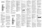
Diode
(1) Set the Function Switch to “Ω/ Cont/ Diode”
position. “Ω “ has been selected by default; press the
SELECT key to change it to “Diode”
Resistance Cont Diode
(2) Connect the red test lead to V/ terminal and the
black test lead to COM terminal.
(3) Connect the red and black test leads to the Anode
and Cathode of the diode under test respectively.
Take the reading on the display. If the connection is
reversed, the display indicates “OL”.
CAUTION
Some of diodes cannot be tested. Indication on
the display will be “OL”.
(Zener diode, LED and so on)
6. Other functions
6-1. Sleep Function
(1) This is a function to prevent the instrument from
being left powered on in order to conserve battery life.
This function causes the instrument to enter Sleep
mode about 15 minutes after the last key operation. To
exit the Sleep mode, turn the Function switch to “OFF”,
then to any other position, or press any Key.
(2) Sleep Function is disabled when;
MIN/MAX Function is selected. Continuous measure-
ment is made with the Sleep Function being disabled.
To activate Sleep Function again, disable the MIN/MAX
function.
CAUTION
The instrument consumes small amount of battery
power in the Sleep mode. Set the Function Switch
to the OFF position after use.
6-2. HOLD Key
(1) Data Hold Function
This is a function to freeze the measured value on the
display. Press the “HOLD” key to freeze the reading.
The reading will be held regardless of subsequent
variation in input. “H” is indicated on the upper left
corner of the display while the instrument is in the Data
Hold mode. To exit Data Hold mode, press the “HOLD”
key again.
CAUTION
Held readings are released when Sleep Function
is activated while the instrument is in the Data Hold
mode.
(2) Backlight ON/OFF (DSA1010 only)
Pressing the HOLD key 2 sec or more lights up the
Backlight. Pressing the HOLD key 2 sec or more again
turns off the Backlight.
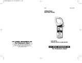
6-3. NCV Function
Red LED on the upper area on the Panel lights up at
all ranges except for OFF when electric field exceeding
100V is detected by the sensor installed in the Jaws.
It indicates a presence of voltage in an electrical circuit
or equipment without touching them.
NCV Sensor can detect electrical
field only from the direction
indicated in the right figure.
Put the fixed element
(left side) closer to the
conductor under test.
Detection against in-wall outlet
is impossible.
DANGER
The LED may not light up due to installation
condition of electrical circuit or equipment. Never
touch the circuit under test to avoid possible
danger even if the LED for NCV doesn’t light up.
Check the functionality of LED on a well-known
power supply prior to measurement. When the
LED doesn’t light up, do not make measurement.
NCV indication is affected by external voltage, how
to hold or place the instrument.
6-4. MIN/MAX Function
CAUTION
SELECT, ZERO, Hz/DUTY keys are disabled
while MIN/MAX Function is being activated.
(1) AC/DC Current Range(AC600A only on DSA660)
Pressing the MIN/MAX Key at 600A & 1000A Function
enables min or max value measurement. Press the
MIN/MAX Key to select MAX or MIN. The max or min
value within measuring range is being held until this
function is disabled. “MIN” or “MAX” is indicated on the
display while this function is being activated.
To disable this function, press down the MIN/MAX
Key at least 2 sec or change functions.
(2) AC/DC Voltage Range
CAUTION
Pressing the MIN/MAX Key without applying voltage
disables the Auto-ranging function and fixes the
range to 6V. Connect the test leads to the circuit
under test and press the MIN/MAX Key after an
appropriate range is selected by Auto-ranging
function.
Pressing the MIN/MAX Key enables min or max value
measurement. Press the MIN/MAX Key to select MAX
or MIN. The max or min value within measuring range
is being held until this function is disabled.
“MIN” or “MAX” is indicated on the display while this
function is being activated.
To disable this function, press down the MIN/MAX Key
at least 2 sec or change functions.
6-5. ZERO Function
CAUTION
MIN/MAX, keys are disabled while ZERO Function is
being activated.
Zero Adjustment Function at Current Range “” mark
is to be indicated at the upper right on the display while
ZERO function is being operated. Indication of relative
value at Current, Voltage, Resistance :Pressing the
ZERO Key indicates REL(relative value) Press the
ZERO Key to save the initial value at the start of
measurement as a reference value. Then the
difference between the later measured values and the
reference value is indicated on the display.
The Auto-ranging function is disabled, while this
function is being activated, and the Range is fixed to
the Range selected at the start of measurement.
Relative value is indicated within following ranges.
(Measuring range) =
(Full-scale value at the fixed Range) – (initial value)
To disable this function, press down the MIN/MAX Key
at least 2 sec or change functions.
A
node
Cathode
6-6. Over-flow indication
When the input exceeds the measuring range at each
Function other than Voltage and 1000A Range, "OL"
or "-OL" is indicated on the display.
7. Battery Replacement
WARNING
To avoid electrical hazard, set the Function Switch
to “OFF” and remove the test leads from the
instrument before trying to replace batteries.
CAUTION
Do not mix old and new batteries.
Install batteries in correct polarity as indicated in
the Battery Compartment.
(1) Replace the batteries when a Low Battery Voltage
warning “BATT” mark is indicated on the display. Note
that when the battery is completely exhausted, the
display blanks without “BATT” mark shown.
(2) Set the Function Switch to “OFF” position.
(3) Unscrew and remove the Battery Compartment
Cover on the bottom of the instrument.
(4) Replace the batteries observing correct polarity.
Use new R03 (AAA) or LR03 / 1.5V batteries.
(5) Install the Battery Compartment and tighten the
screws.
8. Maintenance
Cleaning
Use a cloth dipped in water or neutral detergent for
cleaning the instrument.
Do not use abrasives or solvents. Otherwise, instrument
get damaged, deformed or discolored.
Lifetime Limited Warranty
The attention to detail of this fine snap-around instrument
is further enhanced by the application of A.W. Sperry's
unmatched service and concern for detail and reliability.
These A.W. Sperry snap - arounds are internationally
accepted by craftsmen and servicemen for their
unmatched performance. All A.W. Sperry's snap-around
instruments are unconditionally warranted against defects
in material and workmanship under normal conditions of
use and service; our obligation under this warranty being
limited to repairing or replacing free of charge, at A.W.
Sperry snap-around instrument that malfunctions under
normal operating conditions at rated use.1
Replacement procedure
Securely wrap the instrument and its accessories in a box
or mailing bag and ship prepaid to the address below.
Be sure to include your name and address, as well the
name of the distributor, with a copy of your invoice from
whom the unit was purchased, clearly identifying the
model number and date of purchase.
A.W.SPERRY INSTRUMENTS INC.
ATT: Customer service dept.
2150 Joshua's Path, Suit 302,
Hauppauge, N.Y. 11788
1 .The warranty is not applicable if the instrument has
been: misused, abused, subjected to loads in excess
of specifications, has had unauthorized repair or has
been improperly assembled or used.
*Note: Recommended calibration interval should not
exceed one year. Calibration service charges are not
covered terms and conditions of warranty.
05-11 92-1805
-
 1
1
-
 2
2


Sperry instruments DSA-1010 Owner's manual
- Category
- Measuring, testing & control
- Type
- Owner's manual
Ask a question and I''ll find the answer in the document
Finding information in a document is now easier with AI
Related papers
-
 Sperry instruments DSA-2433R Owner's manual
-
 Sperry instruments DSA500A Owner's manual
-
 Sperry instruments DSA-2417 Owner's manual
-
 Sperry instruments 3165 Owner's manual
-
 Sperry instruments DSA-2002R Owner's manual
-
 Sperry instruments SP-10A Owner's manual
-
 Sperry instruments DSA2003 Owner's manual
-
 Sperry instruments AV2A Owner's manual
-
 Sperry instruments DM-2001 Owner's manual
-
 Sperry instruments DSA600TRMSR Owner's manual


Other documents
-
Sperry DSA1020TRMS User manual
-
Amprobe ACD-330T Clamp-On Multimeter User manual
-
HT HT9025T User manual
-
-
-
 A.W. Sperry Instruments DSA-500 Operating instructions
-
Milwaukee 2236-20 Repair Service Instructions
-
Sanwa DCL1000 User manual
-
RS PRO IPM 244 User manual
-
