Page is loading ...

A
A
Au
u
ut
t
to
o
om
m
ma
a
at
t
ti
i
ic
c
c
T
T
Tr
r
ra
a
an
n
ns
s
sf
f
fo
o
or
r
rm
m
me
e
er
r
r
T
T
Te
e
es
s
st
t
t
S
S
Sy
y
ys
s
st
t
te
e
em
m
m
O
OP
PE
ER
RA
AT
TI
IO
ON
N
M
MA
AN
NU
UA
AL
L
SM6030A

II
Contents
Chapter 1 Out of Box Audit .......................................................................................................... 1
1.1 To Inspect the package ................................................................................................. 1
1.2 Power connection ......................................................................................................... 1
1.3 Fuse .............................................................................................................................. 1
1.4 Environment ................................................................................................................. 1
1.5 Use of Test Fixture ....................................................................................................... 2
1.6 Warm-up ....................................................................................................................... 2
1.7 Other features ............................................................................................................... 2
Chapter 2 Introduction .................................................................................................................. 4
2.1 Introduction to front panel ........................................................................................... 4
2.2 Introduction to rear panel ............................................................................................. 5
2.3 Introduction to display zone ......................................................................................... 6
2.4 Main menu keys and corresponding displayed pages .................................................. 7
2.4.1 [DISP] .......................................................................................................... 7
2.4.2 [SETUP] ....................................................................................................... 8
2.4.3 [SYSTEM SETUP] ...................................................................................... 8
2.5 Basic Operation ............................................................................................................ 9
2.6 Start the instrument ...................................................................................................... 9
Chapter 3 Introduction to [DISP] ................................................................................................ 10
3.1 <MEAS DISPLAY> ................................................................................................... 10
3.1.1 Test function ............................................................................................... 10
3.1.2 Test range ................................................................................................... 13
3.1.3 Test frequency ............................................................................................ 14
3.1.4 Test level .................................................................................................... 15
3.1.5 DC BIAS .................................................................................................... 15
3.1.6 Test speed ................................................................................................... 16
3.1.7 Tools ........................................................................................................... 16
3.1.8 Use USB to Save LCR Test Results ........................................................... 17
3.2 <BIN NO. DISP> ....................................................................................................... 18
3.2.1 Comparator function .................................................................................. 19
3.3 <BIN COUNT DISP> ................................................................................................ 19
3.3.1 PARAM ...................................................................................................... 20
3.3.2 NOM. ......................................................................................................... 20
3.3.3 BIN ............................................................................................................. 20
3.3.4 HIGH/LOW ................................................................................................ 20
3.3.5 COUNT ...................................................................................................... 21
3.3.6 OUT ........................................................................................................... 21
3.4 <LIST SWEEP DISP> ............................................................................................... 21
3.4.1 Sweep mode ............................................................................................... 22
3.4.2 FREQ (Hz) ................................................................................................. 23
3.4.3 Cp[:] D[:] .................................................................................................... 23
3.4.4 CMP (Compare) ......................................................................................... 23

III
3.5 <MEASURE SETUP> ............................................................................................... 23
3.5.1 Trigger mode .............................................................................................. 24
3.5.2 Auto level control function ........................................................................ 25
3.5.3 Average ...................................................................................................... 25
3.5.4 Voltage/Current Level Monitor function .................................................... 25
3.5.5 Trigger Delay ............................................................................................. 26
3.5.6 Step delay ................................................................................................... 26
3.5.7 Output Impedance ...................................................................................... 27
3.5.8 DCR Polarity .............................................................................................. 27
3.5.9 DC Resistance Range ................................................................................. 27
3.5.10 DC Level .................................................................................................... 27
3.5.11 Deviation Test Function ............................................................................. 28
3.6 <CORRECTION> ...................................................................................................... 29
3.6.1 OPEN ......................................................................................................... 30
3.6.2 SHORT ....................................................................................................... 31
3.6.3 LOAD ......................................................................................................... 32
3.6.4 Load correction test function ...................................................................... 34
3.6.5 Cable length selection ................................................................................ 34
3.7 <LIMIT TABLE> ....................................................................................................... 34
3.7.1 Swap parameter .......................................................................................... 35
3.7.2 Limit modes of compare function .............................................................. 35
3.7.3 Set nominal value of tolerance mode ......................................................... 36
3.7.4 Comparator function ON/OFF ................................................................... 37
3.7.5 Auxiliary bin ON/OFF ............................................................................... 37
3.7.6 HIGH/LOW ................................................................................................ 38
3.8 <LIST SWEEP SETUP> ............................................................................................ 39
3.8.1 MODE ........................................................................................................ 39
3.8.2 Test parameter ............................................................................................ 39
3.8.3 Sweep parameter setup ............................................................................... 40
Chapter 4 [SYSTEM] and <FILE MANAGE> .......................................................................... 41
4.1 <SYSTEM SETUP> .................................................................................................. 41
4.1.1 MAIN FUNC ............................................................................................. 41
4.1.2 THEME ...................................................................................................... 41
4.1.3 PASS BEEP ................................................................................................ 42
4.1.4 FAIL BEEP................................................................................................. 42
4.1.5 LANGUAGE .............................................................................................. 43
4.1.6 PASS WORD ............................................................................................. 43
4.1.7 BUS MODE ............................................................................................... 43
4.1.8 GPIB ADDR ............................................................................................... 44
4.1.9 TALK ONLY .............................................................................................. 44
4.1.10 BIAS SRC .................................................................................................. 44
4.1.11 BAUD RATE ............................................................................................. 45
4.1.12 DATA/TIME ............................................................................................... 45
4.2 LCR <FILE LIST> ..................................................................................................... 45

IV
4.2.1 Setup file for single-group component (*.STA) ......................................... 46
4.2.2 U-disk manage performance ...................................................................... 47
4.2.3 Operation steps for file management.......................................................... 47
Chapter 5 Execute LCR operation and some examples .............................................................. 50
5.1 Correction operation................................................................................................... 50
5.1.1 Sweep correction ........................................................................................ 50
5.1.2 Point-frequency correction ......................................................................... 50
5.2 Correct connection of DUT ........................................................................................ 51
5.3 Eliminate the influence of stray impedance ............................................................... 52
5.4 Operation example for testing inductance with SM6030A ........................................ 53
5.5 Operation example of testing capacitance by multi-frequency list sweep ................. 54
5.6 Operation Example of Load Correction ..................................................................... 56
Chapter 6 Transformer Stand Alone Test .................................................................................... 58
6.1 Circuit for Transformer Stand Alone Test .................................................................. 58
6.1.1 Some Parameters of Transformer ............................................................... 58
6.1.2 Capacitance Test between Transformer Windings ...................................... 58
6.2 <TRANS TEST SET> interface ................................................................................. 58
6.2.1 Delay .......................................................................................................... 59
6.2.2 Bias ............................................................................................................. 60
6.2.3 Mode .......................................................................................................... 60
6.2.4 Setting Lx Test Conditions ......................................................................... 61
6.2.5 Setting DCR Test Conditions ..................................................................... 61
6.2.6 Test Frequency, Voltage and Switch ........................................................... 61
6.3 <TRANS LIMIT SET> interface ............................................................................... 62
6.3.1 LMT MODE ............................................................................................... 62
6.3.2 Parameter Column ...................................................................................... 62
6.4 <TRANS MEAS DISP> interface ............................................................................. 62
6.4.1 Save Transformer Single-Group Test Result by U Disk ............................. 63
Chapter 7 Transformer Auto Scanning Test ................................................................................ 64
7.1 Introduction to Scan Test Function ............................................................................ 64
7.2 Install and Connect the Scanning Test System ........................................................... 64
7.3 Upper Panel of Scanning Box .................................................................................... 66
7.4 Lower Panel of Scanning Box .................................................................................... 68
7.5 HANDLER Interface ................................................................................................. 68
7.5.1 Timing Diagram of HANDLER signal ...................................................... 68
7.5.2 Distribution and Connection Diagram for HANDLER .............................. 68
7.6 Example of Transformer ............................................................................................ 70
7.7 <Transformer ID> ...................................................................................................... 70
7.7.1 CLEAR RAM ............................................................................................. 71
7.7.2 Transformer Pin Label ................................................................................ 71
7.7.3 Handler Mode ............................................................................................. 72
7.7.4 AUTOTRIG DELAY ................................................................................. 73
7.7.5 PASS DISP TIME ...................................................................................... 74
7.7.6 SAVE LOG AS ........................................................................................... 74

V
7.7.7 HDL VALID TIME .................................................................................... 75
7.7.8 RELAY ACT TIME .................................................................................... 75
7.7.9 LK. RELAY DLY+ ..................................................................................... 76
7.7.10 DCR RELAY DLY+ ................................................................................... 76
7.7.11 TRANSFORMER ID ................................................................................. 76
7.7.12 PRIMARY NUMS ..................................................................................... 77
7.7.13 SECONDARY NUMS ............................................................................... 77
7.7.14 RESCAN INTERVAL ................................................................................ 77
7.7.15 SCAN DISP MODE ................................................................................... 77
7.7.16 FAIL RESCAN ........................................................................................... 78
7.7.17 DCR MEAS DELAY ................................................................................. 78
7.7.18 DCR OVER DELAY .................................................................................. 78
7.7.19 BIAS ON DELAY ...................................................................................... 78
7.7.20 IGNORE NOM .......................................................................................... 78
7.7.21 TRIGGER DELAY .................................................................................... 79
7.7.22 CYLINDER CTRL .................................................................................... 79
7.8 ALLOCATE PIN TO FIXTURE ................................................................................ 79
7.8.1 PIN TO FIXTURE ..................................................................................... 79
7.9 PIN SETUP ................................................................................................................ 80
7.10 SERIES PIN SHORT SETUP .................................................................................... 82
7.11 PARALELL PIN SHORT SETUP ............................................................................. 82
7.12 <TEST CONDITION> interface ................................................................................ 83
7.12.1 Frequency, Voltage, Switch and Scanning Sequence ................................. 84
7.12.2 Setting TURN Test Conditions ................................................................... 84
7.12.3 Setting Lx Test Conditions ......................................................................... 87
7.12.4 Setting Lk Test Conditions ......................................................................... 91
7.12.5 Setting Cx Test Conditions ......................................................................... 92
7.12.6 Setting Zx Test Conditions ......................................................................... 94
7.12.7 Setting ACR Test Conditions ..................................................................... 95
7.12.8 Setting DCR Test Conditions ..................................................................... 96
7.12.9 Setting PS Test Conditions ......................................................................... 96
7.12.10 Setting BL Test Conditions......................................................................... 98
7.13 <TRANS SCAN TEST> ............................................................................................ 99
7.13.1 Display Zone ............................................................................................ 100
7.13.2 Function Key ............................................................................................ 101
7.13.3 PRI Page-Turning Function ...................................................................... 102
7.13.4 <FILE MANAGE> .................................................................................. 102
7.13.5 Operation Steps for File Manage .............................................................. 103
7.13.6 Stored File of SM6030A .......................................................................... 105
7.13.7 Compatibility of Stored Files ................................................................... 105
7.13.8 Transformer Deviation-Deduction ........................................................... 106
7.13.9 Save Scan Test Results by U Disk ............................................................ 109
7.14 Statistic Page of Transformer Scan Test ................................................................... 109
7.14.1 Reset Statistic Count Value ...................................................................... 110

VI
7.15 Frequently asked questions and answers in transformer scan test............................ 110
7.15.1 High & Low Limits .................................................................................. 110
7.15.2 Measurement item loss ............................................................................. 110
7.15.3 Measurement Interruption ........................................................................ 110
7.15.4 Poor DCR Accuracy ................................................................................. 111
7.15.5 Poor Lk Accuracy ..................................................................................... 111
7.15.6 Inaccurate Turn ......................................................................................... 111
7.15.7 Unstable Turn ........................................................................................... 111
7.15.8 Difference between the first and the second Lx ....................................... 111
7.15.9 Poor Stability of Cx and Zx Open Test Data ............................................ 112
7.15.10 DCR and PS Open Cannot Reach Infinite Large ..................................... 112
7.16 User-made Test Fixture ............................................................................................ 112
7.16.1 Use 1831-EXT1 to Make Test Fixture ..................................................... 112
7.16.2 Example of using 1801-EXT11A(5.0)-B pin signal ................................. 114
7.17 Self-check Function of Scanner Relay ..................................................................... 114
7.17.1 Operation steps for scan self-check .......................................................... 114
7.17.2 Displayed Information on Screen ............................................................. 115
7.17.3 Detection Method for Relay Short ........................................................... 116
7.18 RELAYS ACT COUNT ........................................................................................... 116
7.18.1 View Steps of Scan Box for <RELAYS ACT COUNT>.......................... 116
7.18.2 Screen Display Information Description .................................................. 117
Chapter 8 Performance and Test ............................................................................................... 118
8.1 Test Function ............................................................................................................ 118
8.1.1 Parameter and Symbol ............................................................................. 118
8.1.2 Test combination ...................................................................................... 118
8.1.3 Mathematical Operation ........................................................................... 118
8.1.4 Equivalent mode ....................................................................................... 118
8.1.5 Range ....................................................................................................... 118
8.1.6 Trigger ...................................................................................................... 119
8.1.7 Delay time ................................................................................................ 119
8.1.8 Connection modes of test terminals ......................................................... 119
8.1.9 Test speed (Frequency>=10kHz).............................................................. 119
8.1.10 Average .................................................................................................... 119
8.1.11 Display digit ............................................................................................. 119
8.2 Test signal................................................................................................................. 119
8.2.1 Test signal frequency ................................................................................ 119
8.2.2 Signal mode .............................................................................................. 120
8.2.3 Test signal level ........................................................................................ 120
8.2.4 Output impedance .................................................................................... 120
8.2.5 Monitor for test signal level ..................................................................... 120
8.2.6 Maximum measurement display range ..................................................... 120
8.2.7 DC bias voltage source ............................................................................. 121
8.3 Measurement accuracy ............................................................................................. 121
8.3.1 Accuracies of │Z│,│Y│, L, C, R, X, G, B ........................................ 121

VII
8.3.2 Accuracy of D .......................................................................................... 121
8.3.3 Accuracy of Q .......................................................................................... 122
8.3.4 Accuracy of θ ........................................................................................... 122
8.3.5 Accuracy of G .......................................................................................... 122
8.3.6 Accuracy of Rp ........................................................................................ 122
8.3.7 The accuracy of Rs ................................................................................... 123
8.3.8 Accuracy factor ........................................................................................ 123
8.3.9 Accuracy of DCR ..................................................................................... 126
8.3.10 Lk Accuracy ............................................................................................. 126
8.3.11 Turns to Ratio accuracy ............................................................................ 127
8.4 Safety requirement ................................................................................................... 127
8.4.1 Insulation resistance ................................................................................. 127
8.4.2 Insulation intensity ................................................................................... 127
8.4.3 Leakage current ........................................................................................ 127
8.5 Electromagnetic compatibility ................................................................................. 127
8.6 Performance test ....................................................................................................... 128
8.6.1 Working condition .................................................................................... 128
8.6.2 The used instruments and devices ............................................................ 128
8.6.3 Function check ......................................................................................... 129
8.6.4 Test signal level ........................................................................................ 129
8.6.5 Frequency ................................................................................................. 129
8.6.6 Measurement accuracy ............................................................................. 129
8.6.7 Accuracy of C and D ................................................................................ 129
8.6.8 Accuracy of L ........................................................................................... 129
8.6.9 Accuracy of Z ........................................................................................... 130
8.6.10 Accuracy of DCR ..................................................................................... 130
Chapter 9 Command Reference ................................................................................................ 131
9.1 Subsystem commands for SM6030A ....................................................................... 131
9.1.1 DISPlay subsystem commands ................................................................ 131
9.1.2 FREQuency subsystem commands .......................................................... 133
9.1.3 VOLTage subsystem commands .............................................................. 134
9.1.4 CURRent subsystem commands .............................................................. 134
9.1.5 AMPLitude subsystem commands ........................................................... 134
9.1.6 Output RESister subsystem commands .................................................... 135
9.1.7 BIAS subsystem commands ..................................................................... 135
9.1.8 FUNCtion subsystem commands ............................................................. 137
9.1.9 LIST subsystem commands...................................................................... 140
9.1.10 APERture subsystem commands.............................................................. 144
9.1.11 TRIGger subsystem commands ............................................................... 145
9.1.12 FETCh? subsystem commands ................................................................ 146
9.1.13 CORRection subsystem commands ......................................................... 149
9.1.14 COMParator subsystem commands ......................................................... 155
9.1.15 Mass MEMory subsystem commands ...................................................... 159
9.1.16 TRAN Subsystem Commands ................................................................. 160

VIII
9.2 GPIB Common Commands ...................................................................................... 166
Chapter 10 The description for Handler (optional) ..................................................................... 170
10.1 Technical description ............................................................................................... 170
10.2 The operation description ......................................................................................... 170
10.2.1 The definition for the signal line .............................................................. 170
10.2.2 Electrical feature ...................................................................................... 177
10.2.3 HANDLER Interface board circuit .......................................................... 178
10.2.4 Operation .................................................................................................. 181
Announcement
The description of the manual may not cover all contents of the instrument, and our company is
subject to change and to improve the performance, function, inner structure, appearance, accessory
and package of the instrument without notice. If there is puzzle caused by inconsistency of manual
and instrument, then you can contact with our company by the address on the cover.

1
Chapter 1 Out of Box Audit
When you receive the instrument, some inspections are necessary, and the condition must be
understood and available before installing the instrument.
1.1 To Inspect the package
Inspect the shipping container for damage after unpacking it. It is not recommended to power on the
instrument in the case of a damaged container.
If the contents in the container do not conform to the packing list, notify us or your dealer.
1.2 Power connection
1) Power-supplying voltage range: 100 ~ 120 Vac or 198 ~ 242 Vac. Related to the rear panel
power setting.
2) Power-supplying frequency range: 47~63Hz.
3) Power-supplying power range: not less than 80VA.
4) Power supplying input phase line L, zero line N, ground lead E should be as same as the power
plug of the instrument.
5) After careful design, the instrument can reduce the clutter jamming caused by AC power
terminal input; however, it should be used under the environment with low-noise. Please install
power filter if being unavoidable.
———————————————————————————————————————
Warning: In order to prevent user and instrument from being hurt by leakage, it is necessary
for user to guarantee the ground line of supply power being reliably grounded.
———————————————————————————————————————
1.3 Fuse
The instrument has installed fuse, so operators should use the installed fuse of our company.
———————————————————————————————————————
Warning: Be sure that the location of fuse is consistent with power-supplying voltage range
before charging.
———————————————————————————————————————
1.4 Environment
1) Please do not operate the instrument in the place that is vibrative, dusty, under direct sunlight

2
or where there is corrosive air.
2) The normal working temperature is 0℃~40℃, relative humidity ≤75%, so the instrument
should be used under above condition to guarantee the accuracy.
3) There is heat abstractor on the rear panel to avoid the inner temperature rising. In order to keep
good airiness, please don’t obstruct the left and right airiness holes to make the instrument
maintain the accuracy.
4) Although the instrument has been specially designed for reducing the noise caused by ac power,
a place with low noise is still recommended. If this cannot be arranged, please make sure to use
power filter for the instrument.
5) Please store the instrument in the place where temperature is between 5℃ and 40℃, humidity
is less than 85%RH. If the instrument will not be put in use for a time, please have it properly
packed with its original box or a similar box for storing.
6) The instrument, especially the test cable should be far from strong electro-magnetic field, to
avoid the jamming on measurement.
1.5 Use of Test Fixture
Please use the accessory test fixture or cable, the test fixture made by user or from other
company may cause the incorrect measurement result. The test fixture or cable should be kept
clean, as well as the pin of DUT, thus to guarantee the good connection between DUT and fixture.
Connect the fixture or cable to four test terminals Hcur, Hpot, Lcur, Lpot on the front panel. As for
the DUT with shielding shell, connect shielding layer or ground “┴”.
Note: When test fixture or cable has not being installed, the instrument will display an unstable test
result.
1.6 Warm-up
1) To guarantee the accurate measurement, the warm-up time is no less than 15min.
2) Please not turn on or off instrument frequently, in order to avoid the inner data fluster.
1.7 Other features
1) Power: consumption power≤80VA.
2) Dimension (W*H*D): 235mm*105mm*360mm
3) Shelf Size (W*H*D): 215mm*88mm*335mm
4) Weight: About 3.6 kg.

4
Chapter 2 Introduction
In this chapter, the basic operation features of SM6030A series are described. Please read the
content carefully before using SM6030A series instruments, thus you can learn the operation of
SM6030A.
2.1 Introduction to front panel
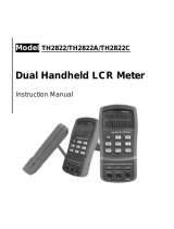
Figure 2-1 shows the front panel of SM6030A.
Figure 2-1 Front panel
1) Brand and model
Brand and model.
2) [DISP]
Press this key to enter into the corresponding measurement display page of instrument
functions.
3) [SETUP]
Press this key to enter into the corresponding measurement setup page of instrument functions.
4) CURSOR
This key is used to move the cursor on the LCD displayed page. When the cursor moves to a
zone, the corresponding zone will be lightened.
5) Numerical keys
These keys are used to input data to the instrument. The key consists of numerical keys [0] to
[9], decimal point [.] and [+/-] key. If the first digit of the input data is the symbol selection,
otherwise it is equivalent to BACKSPACE, the function of deleting the last digit.
(NOTE: long press [.] key is equivalent to copying screen function)

5
6) [KEYLOCK]
Press [KEYLOCK], it will be lighted, which means the function of current panel is locked.
Press it again, it will be off, which means discharging the lock status. If the password function
is ON, it means correct password is necessary when discharging the key-lock, otherwise the
key cannot be unlocked.
When the instrument is controlled by RS232, [KEYLOCK] will be lighted. Press [KEYLOCK]
again, it will be off, which means returning to the local discharging lock status.
7) [BIAS]
[BIAS] is used to permit or forbid the output of 0-50mA/5V DC bias source. Press this key, it
will be lighted which means DC bias output is permitted. Press this key once more, it will be
off which means DC bias output is prohibited. The key is useless in some pages where the DC
BIAS cannot be added. In some non-test pages that cannot be added to DC BIAS, pressing this
key will have no response. When the FUNC is set as DCR, Lp-Rd, Ls-Rd, this function is
invalid.
8) PASS/FAIL indicator
PASS LED indicator shows the test result has passed.
FAIL LED indicator shows the test result has failed.
9) USB HOST interface
Connect U flash disk so as to save or load the file.
10) [RESET]
Press this key to stop scanning only in transformer automatic scanning. No operation will be
executed on other pages.
11) [TRIGGER]
When the trigger mode is set to MAN mode, press this key to trigger the instrument.
12) Test terminals (UNKNOWN)
4-teminal test pair is used to connect 4-terminal test fixture or cable to measure DUT.
The 4 terminals are respectively as follows: Hcur, Hpot, Lpot and Lcur.
Current excitation high end: (Hcur)
High voltage sampling: (Hpot)
Low voltage sampling: (Lpot)
Current excitation low end: (Lcur)
13) LCD
480*272 colorful TFT LCD displays measurement results and conditions.
14) Soft keys
Five soft keys are used to select parameters. The corresponding function of each soft key has
been displayed above. The function definition varies with different pages.
15) POWER
Power switch
2.2 Introduction to rear panel
Figure 2-2 shows the rear panel of SM6030A.

6
RS-232C
DEVICETRIGGER
GPIB HANDLER
!
TO AVOID ELECTRIC SHOCK,
THE POWER CORD PROTECTIVE GROUNDING
CONDUCTOR MUST BE CONNECTED TO GROUND.
DISCONNECT POWER SUPPLY BEFORE
REPLACING FUSE.
WARNING
FUSE
220V/50Hz 80VA T1AL 250V
~
RATING
贴标签
SCANNER
1 2
5 4 3678
9
Figure 2-2 Rear panel
1) SCANNER Interface
Control transformer scan box via SCANNER interface.
2) HANDLER interface
Handler interface is used to realize the sorting output of test results.
3) RS232C interface
Series communication interface can realize the communication with PC.
4) USB DEVICE interface
The tester can communicate with PC through the USB DEVICE interface.
5) TRIGGER interface
The tester can communicate with foot control and other external trigger devices.
6) Power socket
Input AC power.
7) Ground terminal
The ground terminal is connected with instrument casing, being available for protecting or
shielding ground connection.
8) Nameplate
Information about production date, instrument number and manufacturer etc..
9) IEEE-488 (GPIB) interface
The tester can communicate with PC through GPIB interface.
———————————————————————————————————————
Warning: Be sure that the direction of fuse is accordant with power-supply voltage range
before charging.
———————————————————————————————————————
2.3 Introduction to display zone
SM6030A applies a 65k, 4.3-inch TFT display. The display screen is divided into the following

7
zones:
Figure 2-3 display zones
1) Display page name
Indicate the name of the currently displayed page.
2) Soft keys
The zone is used to display the function definition of soft key. The definition of soft key can be
different as the difference of cursor’s direction in the zone.
3) Test result/ condition display zone
In this zone, test result information and current condition are displayed.
4) Assistant Display Zone
This area is used to display system prompts.
2.4 Main menu keys and corresponding displayed pages
2.4.1 [DISP]
When the LCR function is active, press this key-[DISP] to enter into the LCR measurement display
page, mainly about the start button of the capacitance, resistance, inductance, impedance
measurement function menu, the following soft keys will be displayed in the soft key zone.
<MEAS DISPLAY>
<BIN NO. DISP>
<BIN COUNT DISP>
<LIST SWEEP DISP>
<FILE MANAGE>
When the transformer measurement function is active, it is used to enter the transformer
measurement display page. This part of the function page has

8
<TRANS MEAS DISP>
<FILE MANAGE>
When the transformer sweep function is active, it is used to enter the transformer sweep display
page. The function pages of this section are:
<TRANS DEVIATION SETUP>
When positioning scan function is active, there is no function page here.
2.4.2 [SETUP]
When the LCR function is active, press this key-[SETUP], the following soft keys will be displayed
in the soft key zone on the LCR measurement setup page.
<MEASURE SETUP>
<CORRECTION>
<LIMIT TABLE SETUP>
<LIST SWEEP SETUP>
MORE
1/2
<FILE MANAGE>
<SYSTEM SETUP>
<TOOLS>
MORE
2/2
When the transformer measurement function is active, it is used to enter the transformer
measurement display page. This part of the function page has
<TRANS TEST SET>
<TRANS LIMIT SET>
<CORRECTION>
<FILE MANAGE>
When the transformer scan function is active, it is used to enter the transformer scan display page.
The function pages of this section are:
<TRANSFORMER ID>
<PIN SETUP>
<TEST CONDITION>
<STAT>
<FILE MANAGE>
<TOOLS>
When positioning sweep function, same as sweep function.
2.4.3 [SYSTEM SETUP]
This key-[SYSTEM SETUP] is used to enter into the system setup page. The following soft keys
will be available:
<SYSTEM SETUP>
<MEAS SETUP>

9
<DEFAULT SETTING>
<SYSTEM RESET>
2.5 Basic Operation
Basic operation of SM6030A is as follows:
Use menu keys ([DISP], [SETUP]) and soft keys to select the desired page.
Use cursor keys ([←][→] [↑] [↓]) to move the cursor to the desired zone. When the cursor
moves to a specified zone, the zone will become reverse expression.
The soft key functions corresponding to the current zone of the cursor will be displayed in the
soft key zone. Users can select and use the desired soft keys, numeric keys, [BACKSPACE]
and [ENTER] to input data.
When a numeric key is pressed down, the usable unit soft key will be displayed in the soft key
zone. You can choose a unit soft key or [ENTER] to end data inputting. When the data input is
ended using the [ENTER] key, the data unit is the default unit of the corresponding domain
parameter: Hz, V or A. Such as the default unit for test frequency is Hz.
2.6 Start the instrument
Plug in 3-line power plug.
Caution: Keep the power-supply voltage and frequency conform to above specifications. Power
input phase line L, zero line N, ground line E should be the same as that of the instrument.
Press the power switch at the left corner on the front panel and then a boot screen will appear which
displays our company logo, instrument model, and the version number of the software.
Note: The factory password is set in this series of products. The factory password is 2832X. The
user can reset the password according to their needs during use. For details, see the password item
on the <System Settings> page.

10
Chapter 3 Introduction to [DISP]
3.1 <MEAS DISPLAY>
When the LCR function is applied, press [DISP], the <MEAS DISPLAY> page will be displayed on
screen as shown in the following figure.
Pic301
On this page, the test result is displayed in upper-case character. The measurement control
parameters can be set on this page:
Test function (FUNC)
Test frequency (FREQ)
Test level (LEVEL)
Test range (RANGE)
DC BIAS (BIAS)
Test speed (SPEED)
There are 6 zones in this page: FUNC, FREQ, LEVEL, RANG, BIAS and SPEED. The details
will be discussed later.
The test result/ condition display zone shows the information about test condition. These conditions
can be set on <MEAS SETUP> page or <CORRECTION> page.
Signal source voltage/ current monitor (Vm, Im)
Open, short, load correction ON/OFF status (CORR)
3.1.1 Test function
In a measurement period, SM6030A can test four parameters for an impedance component: two
primary parameters and two secondary parameters. Parameters that can be tested are as follows:
Primary parameters
|Z| (Module of impedance)

11
|Y| (Module of admittance)
L (Inductance)
C (Capacitance)
R (Resistance)
G (Conductance)
DCR (DC resistance)
Secondary Parameters
D (Dissipation factor)
Q (Quality factor)
Rs (Equivalent Series Resistance ESR)
Rp (Equivalent Parallel Resistance)
Rd (DC resistance)
X (Reactance)
B (Susceptance)
θ (Phase Angle)
Test results of primary and secondary parameters are respectively displayed in two lines in the form
of upper-case characters. The primary parameter displays in the upper line while the secondary
parameter displays in the lower line.
Operation steps for setting test function:
1) Move the cursor to FUNC zone, the following soft keys will be displayed on the screen.
Cp—…→
Cs—…→
Lp—…→
Ls—…→
MORE→
1/3
2) Press the soft key corresponding to Cp—…→, the following parameters will be shown for your
choice.
Cp-D
Cp-Q
Cp-G
Cp-Rp
RETURN←
Press the soft key corresponding to your desired parameter. Then press RETURN← to return to
upper soft key menu.
3) Press Cs—…→, the following parameters will be shown for your choice.
Cs-D
Cs-Q
Cs-Rs
RETURN←
Press the soft key corresponding to your desired parameter. Then press RETURN← to return to
upper soft key menu.

12
4) Press Lp—…→, the following parameters will be shown for your choice.
Lp-Q
Lp-Rp
Lp-Rd
MORE→
1/2
RETURN←
Press the soft key corresponding to your desired parameter. Then press RETURN← to return to
upper soft key menu.
5) Press MORE→, the following parameters will be shown for your choice.
Lp-D
Lp-G
MORE→
2/2
RETURN←
Press the soft key corresponding to your desired parameter. Then press RETURN← to return to
upper soft key menu.
6) Press Ls—…→, the following parameters will be shown for your choice.
Ls-D
Ls-Q
Ls-Rs
Ls-Rd
RETURN←
Press the soft key corresponding to your desired parameter. Then press RETURN← to return to
upper soft key menu.
7) Press MORE→1/3, the following parameters will be shown for your choice.
Z—…→
Y—…→
R—…→
G-B
MORE→
2/3
Press the soft key corresponding to your desired parameter. Then press MORE to switch to the next
set of functions
8) Press Z—…→, the following parameters will be shown for your choice.
Z-d
Z-r
RETURN←
Press the soft key corresponding to your desired parameter. Then press RETURN← to return to

13
upper soft key menu.
9) Press Y—…→, the following parameters will be shown for your choice.
Y-d
Y-r
RETURN←
Press the soft key corresponding to your desired parameter. Then press RETURN← to return to
upper soft key menu.
10) Press R—…→, the following parameters will be shown for your choice.
R-X
Rp-Q
Rs-Q
RETURN←
Press the soft key corresponding to your desired parameter. Then press RETURN← to return to
upper soft key menu.
11) Press MORE→2/3, the following parameters will be shown for your choice.
DCR
MORE→
3/3
Press DCR, choose the desired parameter. Then press MORE→3/3 to return to the first page of soft
key menu.
3.1.2 Test range
Measurement range should be selected in accordance with the impedance value of the tested LCR
component.
SM6030A has 10 AC measurement ranges: 3Ω, 10Ω, 30Ω, 100Ω, 300Ω, 1kΩ, 3kΩ, 10kΩ, 30kΩ,
100kΩ.
SM6030A has 11 DCR measurement ranges: 1Ω, 3Ω, 10Ω, 30Ω, 100Ω, 300Ω, 1kΩ, 3kΩ, 10kΩ,
30kΩ, 100kΩ.
Operation steps for setting test range:
1) Move the cursor to the RANGE zone, the following soft keys will be displayed:
AUTO The soft key is used to set the range mode to AUTO.
HOLD The soft key is used to switch the AUTO mode to the HOLD mode. When the
range mode is set to HOLD, the range will be locked in the current measurement range.
The current measurement range will be displayed in the range zone.
DECR- The soft key is used to decrease the range under HOLD mode.
INCR+ The soft key is used to increase the range under HOLD mode.
2) Use soft keys to set measurement range.
/