Page is loading ...


Contents
1. INTRODUCTION ............................................................. 1
1.1 G
ENERAL
.......................................................................... 1
1.2 I
MPEDANCE
P
ARAMETERS
................................................ 3
1.3 S
PECIFICATION
.................................................................. 6
1.4 A
CCESSORIES
................................................................. 19
2. OPERATION ................................................................... 20
2.1 P
HYSICAL
D
ESCRIPTION
................................................. 20
2.2 M
AKING
M
EASUREMENT
............................................... 21
2.2.1 Battery Replacement ............................................................... 21
2.2.2 Battery Recharging/AC operation.......................................... 22
2.2.3 Open and Short Calibration ...................................................23
2.2.4 Display Speed.......................................................................... 24
2.2.5 Relative Mode ......................................................................... 24
2.2.6 Range Hold ............................................................................. 24
2.2.7 DC Resistance Measurement.................................................. 25
2.2.8 AC Impedance Measurement.................................................. 25
2.2.9 Capacitance Measurement ..................................................... 25
2.2.10 Inductance Measurement........................................................ 26
2.3 A
CCESSORY
O
PERATION
................................................. 27
3. INFRARED OPERATION............................................. 29
3.1 C
OMMAND
S
YNTAX
........................................................ 30
3.2 C
OMMANDS
.................................................................... 31
4. APPLICATION ............................................................... 39
4.1 T
EST
L
EADS
C
ONNECTION
............................................. 39
4.2 O
PEN
/S
HORT
C
OMPENSATION
........................................ 44
4.3 S
ELECTING THE
S
ERIES OR
P
ARALLEL
M
ODE
................. 46
5. WARRANTY INFORMATION ..................................... 49
6. SAFETY PRECAUTION ............................................... 51

1
1. Introduction
1.1 General
The MT4080 is a high accuracy handheld LCR meter that can
perform the inductor, capacitor and resistor measurement up to
100KHz within 0.2% basic accuracy. It is the most advanced
handheld AC/DC impedance measurement instrument to date. The
MT4080 can help engineers and students to understand the
characteristic of electronics components. It is also of great
assistance to those people who want to do the quality control of the
electronics components.
The instrument is auto or manual ranging. Test frequencies of
100Hz, 120Hz, 1KHz, 10KHz or 100KHz (MT4080A only) may
be selected on all applicable ranges. The test voltages of
50mVrms, 0.25Vrms, 1Vrms or 1VDC (DCR only) may also be
selected on all applicable ranges. The dual display feature permits
simultaneous measurements.
Components can be measured in the series or parallel mode as
desired; the more standard method is automatically selected first
but can be overridden.
The highly versatile MT4080 can perform virtually all the
functions of most bench type LCR bridges. With a basic accuracy
of 0.2%, this economical LCR meter may be adequately
substituted for a more expensive LCR bridge in many situations.
The meter is powered from two AA Batteries and is supplied with
an AC to DC charging adapter and two AA Ni-Mh Rechargeable

2
Batteries.
The instrument has applications in electronic engineering labs,
production facilities, service shops, and schools. It can be used to
check ESR values of capacitors, sort values, select precision values,
measure unmarked and unknown inductors, capacitors or resistors,
and to measure capacitance, inductance, or resistance of cables,
switches, circuit board foils, etc.
The key features are as following:
Test condition:
1 Frequency : 100Hz / 120Hz / 1KHz / 10KHz /
100KHz (MT4080A only)
2. Level : 1Vrms / 0.25Vrms / 50mVrms /
1VDC (DCR only)
Measurement Parameters : Z, Ls, Lp, Cs, Cp,
DCR, ESR, D, Q and
θ
Basic Accuracy: 0.2%
Dual Liquid Crystal Display
Fast/Slow Measurement
Auto Range or Range Hold
Infrared Interface Communication
Open/Short Calibration
Primary Parameters Display:
Z : AC Impedance
DCR : DC Resistance
Ls : Serial Inductance
Lp : Parallel Inductance
Cs : Serial Capacitance
Cp : Parallel Capacitance

3
Second Parameter Display:
θ
: Phase Angle
ESR : Equivalence Serial Resistance
D : Dissipation Factor
Q : Quality Factor
Combinations of Display:
Serial Mode : Z –
θ
, Cs – D, Cs – Q, Cs – ESR, Ls –
D, Ls – Q, Ls – ESR
Parallel Mode : Cp – D, Cp – Q, Lp – D, Lp – Q
1.2 Impedance Parameters
Due to the different testing signals on the impedance measurement
instrument, there are DC impedance and AC impedance. The
common digital multi-meter can only measure the DC impedance,
but the MT4080 can do both. It is a very important issue to
understand the impedance parameters of the electronic component.
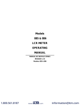
When we analysis the impedance by the impedance measurement
plane (Figure 1.1). It can be visualized by the real element on the
X-axis and the imaginary element on the y-axis. This impedance
measurement plane can also be seen as the polar coordinates. The
Z is the magnitude and the
θ
is the phase of the impedance.

4
(
)
()
()
()
()
Ohm
Reactance
Resistance
Impedance
1
22
=Ω
=
=
=
==
+==
Ω∠=+=
−
S
S
s
s
s
sss
ss
X
R
Z
R
X
TanSinZX
XRZCosZR
ZjXRZ
θθ
θ
θ
There are two different types of reactance: Inductive (X
L
) and
Capacitive (X
C
). It can be defined as follows:
Also, there are quality factor (Q) and the dissipation factor (D) that
need to be discussed. For component, the quality factor serves as a
measure of the reactance purity. In the real world, there is always
s
X
s
R
(
)
sX,RZ s
Z
θ
Imaginary Axis
Real Axis
Figure 1.1
)(
)(tan
2
11
)(tan2
HzFrequencyf
FceCapaciC
fCC
X
HceInducLfLLX
C
L
=
===
=
==
πω
π
ω

5
some associated resistance that dissipates power, decreasing the
amount of energy that can be recovered. The quality factor can be
defined as the ratio of the stored energy (reactance) and the
dissipated energy (resistance). Q is generally used for inductors
and D for capacitors.
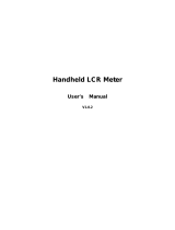
There are two types of the circuit mode. One is series mode, the
other is parallel mode. See Figure 1.2 to find out the relation of the
series and parallel mode.
pp
p
p
p
p
sss
s
s
s
RC
L
R
X
R
G
B
RCR
L
R
X
D
Q
ω
ω
ω
ω
δ
===
=
===
==
1
tan
11

6
1.3 Specification
LCD Display Range:
Parameter Range
Z 0.000
Ω
to 9999 M
Ω
L 0.000 µH to 9999 H
C 0.000 pF to 9999 F
DCR 0.000
Ω
to 9999 M
Ω
ESR 0.000
Ω
to 9999
Ω
D 0.000 to 9999
Q 0.000 to 9999
θ
-180.0
°
to 180.0
°
Figure 1.2
Real and imaginary components are serial
ss jXRZ
+
=
Rs jX
s
Real and imaginary components are Parallel
G=1/Rp
j
B=1/jXp
jBGY
+
=
j
Xp
Rp
P
jX
1
P
R
1
Y+=

7
Accuracy (
Ae
):
Z Accuracy:
|Zx|
Freq.
20M ~
10M
(
Ω
)
10M ~
1M
(
Ω
)
1M ~
100K
(
Ω
)
100K ~
10
(
Ω
)
10 ~ 1
(
Ω
)
1 ~ 0.1
(
Ω
)
DCR
100Hz
120Hz
1KHz
2%
±
1
1%
±
1
10KHz 5%
±
1
2%
±
1
0.5%
±
1
0.2%
±
1
0.5%
±
1
1%
±
1
100KHz
(4080A)
NA 5%
±
1
2%
±
1 0.4%
±
1
2%
±
1 5%
±
1
Note : 1. The accuracy applies when the test level is set to 1Vrms.
2
.Ae
multiplies 1.25 when the test level is set to
250mVrms.
3
.Ae
multiplies 1.50
when the test level is set to 50mVrms.
4.When measuring L and C, multiply
Ae
by
2
1Dx+
if
the Dx
>
0.1.
:
Ae
is not specified if the test level is set to 50mV.

8
C Accuracy :
79.57
pF
159.1
pF
159.1
pF
|
1.591
nF
1.591
nF
|
15.91
nF
15.91
nF
|
159.1
uF
159.1
uF
|
1591
uF
1591
uF
|
15.91
mF
100Hz
2%
±
1
X
1%
±
1 0.5%
±
1
0.2%
±
1
0.5%
±
1
1%
±
1
X
66.31
pF
|
132.6
pF
132.6
pF
|
1.326
nF
1.326
nF
|
13.26
nF
13.26
nF
|
132.6
uF
132.6
uF
|
1326
uF
1326
uF
|
13.26
mF
120Hz
2%
±
1
X
1%
±
1 0.5%
±
1
0.2%
±
1
0.5%
±
1
1%
±
1
X
7.957
pF
|
15.91
pF
15.91
pF
|
159.1
pF
159.1
pF
|
1.591
nF
1.591
nF
|
15.91
uF
15.91
uF
|
159.1
uF
159.1
uF
|
1.591
mF
1KHz
2%
±
1
X
1%
±
1 0.5%
±
1
0.2%
±
1
0.5%
±
1
1%
±
1
X
0.795
pF
|
1.591
pF
1.591
pF
|
15.91
pF
15.91
pF
|
159.1
pF
159.1
pF
|
1.591
uF
1.591
uF
|
15.91
uF
15.91
uF
|
159.1
uF
10KHz
5%
±
1
X
2%
±
1 0.5%
±
1
0.2%
±
1
0.5%
±
1
1%
±
1
X
NA 0.159
pF
|
1.591
pF
1.591
pF
|
15.91
pF
15.91
pF
|
159.1
nF
159.1
nF
|
1.591
uF
1.591
uF
|
15.91
uF
100KHz
(4080A)
NA 5%
±
1
X
2%
±
1 0.4%
±
1
2%
±
1 5%
±
1
X

9
L Accuracy :
31.83
KH
|
15.91
KH
15.91
KH
|
1591
H
1591
H
|
159.1
H
159.1
H
|
15.91
mH
15.91
mH
|
1.591
mH
1.591
mH
|
159.1
uH
100Hz
2%
±
1
X
1%
±
1 0.5%
±
1
0.2%
±
1
0.5%
±
1
1%
±
1
X
26.52
KH
|
13.26
KH
13.26
KH
|
1326
H
1326
H
|
132.6
H
132.6
H
|
13.26
mH
13.26
mH
|
1.326
mH
1.326
mH
|
132.6
uH
120Hz
2%
±
1
X
1%
±
1 0.5%
±
1
0.2%
±
1
0.5%
±
1
1%
±
1
X
3.183
KH
|
1.591
KH
1.591
KH
|
159.1
H
159.1
H
|
15.91
H
15.91
H
|
1.591
mH
1.591
mH
|
159.1
uH
159.1
uH
|
15.91
uH
1KHz
2%
±
1
X
1%
±
1 0.5%
±
1
0.2%
±
1
0.5%
±
1
1%
±
1
X
318.3
H
|
159.1
H
159.1
H
|
15.91
H
15.91
H
|
1.591
H
1.591
H
|
159.1
uH
159.1
uH
|
15.91
uH
15.91
uH
|
1.591
uH
10KHz
5%
±
1
X
2%
±
1 0.5%
±
1
0.2%
±
1
0.5%
±
1
1%
±
1
X
31.83
H
|
15.91
H
15.91
H
|
1.591
H
1.591
H
|
159.1
mH
159.1
mH
|
15.91
uH
15.91
uH
|
1.591
uH
1.591
uH
|
0.159
uH
100KHz
(4080A)
NA 5%
±
1
X
2%
±
1 0.4%
±
1
2%
±
1 5%
±
1
X

10
D Accuracy :
|Zx|
Freq.
20M ~
10M
(
Ω
)
10M ~
1M
(
Ω
)
1M ~
100K
(
Ω
)
100K ~
10
(
Ω
)
10 ~ 1
(
Ω
)
1 ~ 0.1
(
Ω
)
100Hz
120Hz
1KHz
±
0.020
±
0.010
10KHz
±
0.050
±
0.020
±
0.005
±
0.002
±
0.005
±
0.010
100KHz
(4080A)
NA
±
0.050
±
0.020
±
0.004
±
0.020
±
0.050
θ Accuracy :
|Zx|
Freq.
20M ~
10M
(
Ω
)
10M ~
1M
(
Ω
)
1M ~
100K
(
Ω
)
100K ~
10
(
Ω
)
10 ~ 1
(
Ω
)
1 ~ 0.1
(
Ω
)
100Hz
120Hz
1KHz
±
1.046
±
0.523
10KHz
±
2.615
±
1.046
±
0.261
±
0.105
±
0.261
±
0.523
100KHz
(4080A)
NA
±
2.615
±
1.046
±
0.209
±
1.046
±
2.615

11
Z Accuracy:
As shown in table 1.
C Accuracy:
Cxf
Zx ⋅⋅⋅
=
π
2
1
C
Ae
= Ae of |Zx|
f : Test Frequency (Hz)
Cx : Measured Capacitance Value (F)
|Zx| : Measured Impedance Value (
Ω
)
Accuracy applies when Dx (measured D value)
≦
0.1
When Dx > 0.1, multiply C
Ae
by
2
1Dx+
Example:
Test Condition:
Frequency : 1KHz
Level : 1Vrms
Speed : Slow
DUT : 100nF
Then
Ω=
⋅⋅⋅⋅
=
⋅⋅⋅
=
−1590
10100102
1
2
1
93
π
π
Cxf
Zx
Refer to the accuracy table, get C
Ae
=±0.2%

12
L Accuracy:
LxfZx ⋅⋅⋅=
π
2
L
Ae
= Ae of |Zx|
f : Test Frequency (Hz)
Lx : Measured Inductance Value (H)
|Zx| : Measured Impedance Value (
Ω
)
Accuracy applies when Dx (measured D value)
≦
0.1
When Dx > 0.1, multiply L
Ae
by
2
1Dx+
Example:
Test Condition:
Frequency : 1KHz
Level : 1Vrms
Speed : Slow
DUT : 1mH
Then
Ω=⋅⋅⋅=
⋅⋅⋅=
−283.610102
2
33
π
π
LxfZx
Refer to the accuracy table, get L
Ae
=±0.5%
ESR Accuracy:
100
Ae
XxESRAe ⋅±=
Cxf
LxfXx ⋅⋅⋅
=⋅⋅⋅=
π
π
2
1
2

13
ESR
Ae
= Ae of |Zx|
f : Test Frequency (Hz)
Xx : Measured Reactance Value (
Ω
)
Lx : Measured Inductance Value (H)
Cx : Measured Capacitance Value (F)
Accuracy applies when Dx (measured D value)
≦
0.1
Example:
Test Condition:
Frequency : 1KHz
Level : 1Vrms
Speed : Slow
DUT : 100nF
Then
Ω=
⋅⋅⋅⋅
=
⋅⋅⋅
=
−1590
10100102
1
2
1
93
π
π
Cxf
Zx
Refer to the accuracy table, get
C
Ae
=±0.2%,
Ω±=⋅±= 18.3
100
Ae
XxESRAe
D Accuracy:
100
Ae
DAe ±=

14
D
Ae
= Ae of |Zx|
Accuracy applies when Dx (measured D value)
≦
0.1
When Dx > 0.1, multiply Dx by (1+Dx)
Example:
Test Condition:
Frequency : 1KHz
Level : 1Vrms
Speed : Slow
DUT : 100nF
Then
Ω=
⋅⋅⋅⋅
=
⋅⋅⋅
=
−1590
10100102
1
2
1
93
π
π
Cxf
Zx
Refer to the accuracy table, get
C
Ae
=±0.2%,
002.0
100 ±=⋅±= Ae
DAe
Q Accuracy:
DeQx
DeQx
Ae
Q⋅
⋅
±= m1
2
Q
Ae
= Ae of |Zx|
Qx : Measured Quality Factor Value
De : Relative D Accuracy


16
Example:
Test Condition:
Frequency : 1KHz
Level : 1Vrms
Speed : Slow
DUT : 100nF
Then
Ω=
⋅⋅⋅⋅
=
⋅⋅⋅
=
−1590
10100102
1
2
1
93
π
π
Cxf
Zx
Refer to the accuracy table, get
Z
Ae
=±0.2%,
deg115.0
100
2.0180
100
Ae180
Ae
±=⋅
π
±=
⋅
π
±=θ
Testing Signal:
Level Accuracy :
±
5%
Frequency Accuracy : 0.1%
Output Impedance : 100
Ω
±
5%
Measuring Speed:
Fast : 4.5 meas. / sec.
Slow : 2.5 meas. / sec.

17
General:
Temperature : 0
°
C to 70
°
C (Operating)
-20
°
C to 70
°
C (Storage)
Relative Humidity : Up to 85%
Battery Type : 2 AA size Ni-Mh or Alkaline
Battery Charge : Constant current 150mA
approximately
Battery Operating Time : 2.5 Hours typical
AC Operation : 110/220V AC, 60/50Hz with
proper adapter
Low Power Warning : under 2.2V
Dimensions : 174mm x 86mm x 48mm (L x W
x H) 6.9” x 3.4” x 1.9”
Weight : 470g
Considerations
Test Frequency. The test frequency is user selectable and can be
changed. Generally, a 1kHz test signal is used to measure
capacitors that are 0.01uF or smaller and a 120Hz test signal is
used for capacitors that are 10uF or larger. Typically a 1 kHz test
signal is used to measure inductors that are used in audio and RF
(radio frequency) circuits. This is because these components
operate at higher frequencies and require that they be measured at
a higher frequency of 1kHz. Generally, inductors below 2mH
should be measured at 1 kHz and inductors above 200H should be
measured at 120Hz.
It is best to check with the component manufacturer’s data sheet to
determine the best test frequency for the device.

18
Charged Capacitors. Always discharge any capacitor prior to
making a measurement since a charged capacitor may seriously
damage the meter.
Effect Of High D on Accuracy. A low D (Dissipation Factor)
reading is desirable. Electrolytic capacitors inherently have a
higher dissipation factor due to their normally high internal
leakage characteristics. If the D (Dissipation Factor) is excessive,
the capacitance measurement accuracy may be degraded.
It is best to check with the component manufacturers data sheet to
determine the desirable D value of a good component.
Combining Autoranging and Manual Ranging Operation.
Combining autoranging and manual ranging is a very convenient
way to gain the advantage of both modes. Starting in the
autoranging mode, insert or connect the inductor to be measured,
The instrument quickly steps to the correct range for measurement.
Next, press the
RANGE key to switch to the manual
ranging
mode. The instrument will be on the correct range. The display will
indicate whether a calibration needs to be performed to obtain
optimum accuracy. If not, take the reading. If so, perform the
calibration then take the reading, This method combines the speed
of autoranging and the accuracy of manual ranging and is very
easy and simple to perform.
Series Vs Parallel Measurement (for Inductors). The MT4080
normally measures inductance in the series equivalent mode. The
series mode displays the more accurate measurement in most cases.
/