
Terms in this manual
These terms may appear in this manual:
WARNING. Warning statements identify conditions or
practices that could result in injury or loss of life.
CAUTION. Caution statements identify conditions or
practices that could result in damage to this product or
other property.
Symbols and terms on the product
When this symbol is marked on the product, be
sure to consult the manual to find out the nature of
the potenti
al hazards and any actions which have
to be taken to avoid them. (This symbol may also
be used to refer the user to ratings in the manual.)
The following symbol(s) may appear on the product:
Complianc
e information
This product i s intended for use by professionals and trained
personnel
only; it is not designed for use in households or by
children.
Questions about the following compliance information may be
directed to the following address:
Tektronix, Inc.
PO Box 5 00, MS 19-045
Beaverton, OR 97077, USA
www.tek.com
Environmental considerations
This section provides information about the environmental
impact of the product.
Restrict
ion of hazardous substances
Complies with RoHS2 Directive 2011/65/EU.
Product end-of-life handling
Observe the following guidelines when recycling an instrument
or component:
Equipment recycling. Production of this equipment required
the extraction and use of natural resources. The equipment may
contain substances that could be harmful to the environment or
human health if improperly handled
at the product’s end of life.
To avoid release of such substances into the environment and
to reduce the use of natural resources, we encourage you to
recycle this product in an appropriate system that will ensure
thatktronixpart number
English 077-1542-xx
Japanese 077-1543-xx
Simplified
Chinese
077-1544-xx
Environmental s pecifications
Specification Description
Maximum input
voltage
DC: ±60 V
AC: ±30 V RMS
Pk-Pk: ±42 V peak
Temperature
Probe body: 0 to +55 °C
Standard accessories: –40 to +125 °C
High-temp accessories: –55 to +155 °C
Humidity
5 to 95% up to +40 °C, derate to 85% above
+40 °C
Altitude 0 to 3000 m
1
2
3
4
Key performance specifications
Specification Description
Oscilloscope
compatibility
6 series MSO, 5 series MSO,
MSO/DPO3000, MDO/DPO4000,
MSO/DPO5000, DPO7000, and
DPO70000
1
o
scilloscopes
Bandwidth in DC
coupling mode
2 3
TPR1000: DC to1GHz
TPR4000: DC to4GHz
Bandwidth in DC
reject mode
2 3
TPR1000: 10 kHz to1GHz
TPR4000: 10 kHz to4GHz
Linear dynamic
range
Up to 60 V DC, ±1 V
p-p
to bandwidth
4
Offset range
±60 V
Attenuation 1.25x
2
Measurement
accuracy
DC linearity: <0.1%
Step resp
onse long-term aberrations: ±1%
Noise
<300 μV
p-p
noise on6Series MS O (20 MHz
BW Limit)
<1 mV
p-p
noise on 6 Series MSO (Full
Bandwidth)
Input impedance
50 kΩ DC to
10 kHz
50 Ω AC > 100 kHz
Offset ±60 V offset range
Offset setting error: ±2 mV max, ±0.4 μV
typical
DPO70000 oscillosc opes require the optional TCA-VPI50 adapter.
Frequency response optimized for < 1 Ω source impedance.
Through S MA-to-SMA cable or Solder Micro-Coax tip.
Max AC RMS of 1 V.
Standard accessories
Each probe is shipped with one TPR4KIT accessory kit
containing the following items:
noitpircseDmetI
1.3 m cable, SMA male-to-MMCX
male, 50 Ω
1.3 m ca
ble, SMA male-to-SMA male,
50 Ω
Y-lead adapter, MMCX
femal
e-to-0.8 mm sockets
Adapter cable, MMCX female-to-U.FL
female, 50 Ω
Adapter, MMCX female-to-square pin
(0.0
62 centers)
DUT interface solder pins, set of 20
Soldering aide tool, 0.0 62 solder pins
ove
r SMT
Solder-in cable adapter, MMCX
female-to-solder micro-coax tip, 50 Ω,
set of 3
Solder-in cable adapter, MMCX
female-to-solder flex-paddle tip, 50Ω,
set of 3
Wire card, solderable enameled
self-fluxing copper wire (for use with
the solder-in tips)
Probe tip tripod support (with living
hinge)
Marker bands, set of 5 ( for probe
identification)
xx
Important Safety information
This manual contains information and warnings that must be
followed by the user for safe operation and to keep the product
in a safe condition.
To safely perform service on this product, additional
information is provided at the end of this section in the Service
safety summary.
General sa fety summary
Use the product only as specified. Review the following safety
precautions to avoid injury and prevent damage to this product
or any products connected to it. Carefully read all instructions.
Retain these instructions for future reference.
Probes and test leads
Befor
e connecting probes or test leads, connect the power cord
from the power connector to a properly grounded power outlet.
Inspect the probe and accessories. Before each use, inspect
probe
and accessories for damage (cuts, tears, or defects in
the probe bod y,
accessories, or cable jacket). Do not use if
dama
ged.
High temperature probe tips
WARNING. To prevent a burn injury, when usingasolder
micro-coax or flex tip in a high temperature application, be
sure to allow the tip to cool down before handling the tip.
Service safety summary
The Service safety summary section contains additional
information required to safely perform service on the product.
Only qualified personnel should perform service p rocedures.
Read this Service safety summary a nd the General safety
summary before performing any service procedures.
Do not service alone. Do not perform internal service or
adjustments of this product unless another person capable of
rendering first aid and resuscitation is present.
TPR1000 and TPR4000
Active Power Rail Probes
Complian
ce and Safety Instructions
x
1
*P0713
63700*
071-3637-00

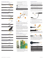
1. To install the probe, slide the probe body into the
FlexChannel or VPI receptacle. The probe clicks into
place when fully engaged.
2. Attach one of the following probe cables to the SMA
connector on the probe body:
SMA-to-SMA standard cable (standard accessory)
SMA-to-MMCX standard cable (standard accessory)
SMA-to-MMCX high-temperature cable (optional
accessory)
1 GHz browser probe cable (optional accessory)
CAUTION. To
prevent damage to the probe, do not exceed
8 in-lbs torque on the SMA nut.
3. To disconnect the probe, press the latch release button and
pull away fr
om the instrument.
Attaching MM CX accessories
Gently insert the MMC X end of the cable into one o f the
following accessories: micro-coax tip, solder flex tip, u.fl
adapter or MMCX to square pin Y-lead adapter, until you feel
the connector engage. To remove an accessory, gently pull
from t he MMCX connection point.
Attaching solder-in accessories
Micro-coax tip. For convenient first-time use, the solder
micro-coax tips are shipped pre-trimmed and ready to be
soldered to the test point. You can reuse a tip by removing the
tip from the solder joint and then trimming the wire insulation
back to expose the center pin and ground shield on the tip cable.
To achieve the best measurements results with a trimmed tip,
refer to the TPR1000 and TPR4000 User Manual for guidelines
and a descripti
on of best practices.
Flex tip. To attach the solder flex tip, first solder the enameled
self- fluxing copper wire (standard accessory) to the test point.
Feed the wire through the vias on the end of the flex tip, and
then apply a small amount of solder to the vias to attach the
wire to the tip.
Using the solder-pin installation tool
The supplied set of solder pins are intended to be installed
on DUT circuit boards and used with the supplied
MMCX-to-square-pin adapter. To install the solder pins, use
the supplied soldering-aide tool as described below .
NOTE. The solder pins are extremely small and can be
challenging to handle. It is recommended t o use tweezer s and a
magnifying tool when installing pins on a circuit board.
1. Carefully insert the solder pins into the soldering aide tool
as shown below.
2. Use the soldering aide tool to hold the solder pins in place
while
soldering the pins to the circuit board.
3. If necessary, apply a small amount of adhesive t o further
strengthen the connection to the circuit board. However,
keep the height of the adhesive to a minimum to provide
good electrical contact for the adapter.
Optional high-temperature accessory kit
If you ordered th e optional TPR4KITHT high-temperature
accessory kit, you received the following items:
noitpircseDmetI
2 m high- temperature cable, SMA
male-to-MMCX male, 50 Ω
Solder-in cable adapter, MMCX
female-to-solder micro-coax tip, 50 Ω,
set of 3
Solder-in cable adapter, MMCX
female-to-solder flex-paddle tip, 50Ω,
set of 3
Optional 1 GHz browser accessory kit
If you ordered the optional TPRBRWSR1G browser accessory
kit, you received the following items:
noitpircseDmetI
Browser
Ground leads (blade, 0.5 mm spring,
15 cm alligator)
Y-lead adapter, browser tip-to-0.8 m m
sockets
Micro-SMD clip
Replac
ement 0.5 mm browser tips
(2 solid tips, 2 spring tips)
Optional solder-in, micro-coax tip accessory kit
If you ordered the optional TPR4SIACOAX accessory kit, you
received the following items:
noitpircseDmetI
Solder-in cable adapter, MMCX
female-to-solder micro-coax tip, 50 Ω,
set of 3
Optional solder-in, flex-paddle tip acc essory kit
If you ordered the optional TPR4SIAFLEX accessory kit, you
received the following items:
noitpircseDmetI
Solder-in cable adapter, MMCX
female-to-solder flex-paddle tip, 50Ω,
set of 3
Installation
NOT
E. Your FlexChannel or VPI instrument may require a
software upgrade to support full functionality of the TPR1000
and
TPR4000 probes. Before you connect the probe to an
oscilloscope, refer to the required software versions table at the
end
of this document to check the version requirements.
Copyright © Tektronix, Inc. A ll r ights reserved.
Using the optional1GHz browser
The optional 1 GHz browser kit contains the following parts:
1 GHz browser probe, square pin Y-lead adapter, micro-SMD
clip, three ground leads (alligator, blade, spring), and four
replacement probe-tip pins (two rigid, tw o spring loaded).
WARNING. To prevent injury to the operator or damage
to the probe, oscilloscope and device under test, do not
touch the probe ground to any point that is not at th e same
potential as the chassis ground of the oscilloscope. The
probe ground must be connected to the same potential as
the chassis ground of the oscilloscope.
Installing ground leads. To obtain accurate measurements,
always attach a ground lead to the probe tip before making
measurements. It is recommended that you use the shortest
ground lead that will function in your electrical application. The
following illustration shows the browser probe tip , the tip cover
and the three types of grounds leads supplied with the browser.
To install the ground leads:
Spring: Slide the ground lead over the prob
e tip until it
seats around the metal portion of the probe-tip housing.
Alligator: Slide the ground lead prongs over the exposed
metal betwe e n the plastic probe-tip sections.
Blade: Locate the slot i n the probe-tip housing as shown
below. Slide the ground lead over the probe tip until the
blade slides into the slot.
Connecting the Y-lead adapter and micro-SMD clip. The browser
kit includes a Y-lead adapter and a micro-SMD clip that connect
as shown below. The Y-lead adapter can also connect to square
pins.
Replacing browser-tip pins. To remove the browser-tip pin, use
pliers to grasp the pin and gently pull it out of the tip housing.
To install a new browser-tip pin, select between a solid (silver
colored) or spring-loaded (gold colored) pin, and then use pliers
to gently insert the pin into the browser-tip housing until you
feel the pin press against the bottom of the housing.
Required osc illoscope software v ersions
Oscilloscope Required software version
1
5 and 6 Series MSO
1.12.5
MSO/DPO3000
1.27462
MDO/DPO4000
1.09354
MDO/DPO5000
10.8.3.3
DPO7000
10.8.3.3
DPO70000
10.9.1
1
The probe may operate with older versions of oscilloscope software. However,
older software versions than those listed are not guaranteed to provide full
probe functionality.
www.tek.com
-
 1
1
-
 2
2


Tektronix TPR1000 Compliance And Safety Instructions
- Type
- Compliance And Safety Instructions
- This manual is also suitable for
Ask a question and I''ll find the answer in the document
Finding information in a document is now easier with AI
Related papers
-
Tektronix TPR1000 User manual
-
-
-
-
-
-
-
-
-
Other documents
-
SIGLENT SDS7000A Digital Storage Oscilloscope User manual
-
InLine 43047D Datasheet
-
Multitech MTSMC-H5-U.R2 User guide
-
Keysight InfiniiVision MSO-X 4034A User manual
-
NXP KW40Z User manual
-
 RIM 1802G Integrator manual
-
Agilent Technologies InfiniiVision 3000 X-Series User manual
-
Multi-Tech SocketModem MTSMC-G-F1 Developer's Manual
-
NXP GD3100 User guide
-
COBHAM GR716-MINI User manual
