Page is loading ...

UM11108
FRDM-GD3100EVM half-bridge evaluation board
Rev. 5 — 10 February 2020 User manual
Important Notice
NXP provides the enclosed product(s) under the following conditions:
This evaluation kit is intended for use of ENGINEERING DEVELOPMENT OR EVALUATION PURPOSES ONLY. It is provided as a
sample IC pre-soldered to a printed circuit board to make it easier to access inputs, outputs, and supply terminals. This evaluation board
may be used with any development system or other source of I/O signals by simply connecting it to the host MCU or computer board via
off-the-shelf cables. This evaluation board is not a Reference Design and is not intended to represent a final design recommendation for
any particular application. Final device in an application will be heavily dependent on proper printed circuit board layout and heat sinking
design as well as attention to supply filtering, transient suppression, and I/O signal quality.
The goods provided may not be complete in terms of required design, marketing, and or manufacturing related protective considerations,
including product safety measures typically found in the end product incorporating the goods. Due to the open construction of the product,
it is the user's responsibility to take any and all appropriate precautions with regard to electrostatic discharge. In order to minimize risks
associated with the customers applications, adequate design and operating safeguards must be provided by the customer to minimize
inherent or procedural hazards. For any safety concerns, contact NXP sales and technical support services.
Should this evaluation kit not meet the specifications indicated in the kit, it may be returned within 30 days from the date of delivery and will
be replaced by a new kit.
NXP reserves the right to make changes without further notice to any products herein. NXP makes no warranty, representation or
guarantee regarding the suitability of its products for any particular purpose, nor does NXP assume any liability arising out of the
application or use of any product or circuit, and specifically disclaims any and all liability, including without limitation consequential or
incidental damages. “Typical” parameters can and do vary in different applications and actual performance may vary over time. All
operating parameters, including “Typical”, must be validated for each customer application by customer’s technical experts.
NXP does not convey any license under its patent rights nor the rights of others. NXP products are not designed, intended, or authorized
for use as components in systems intended for surgical implant into the body, or other applications intended to support or sustain life, or
for any other application in which the failure of the NXP product could create a situation where personal injury or death may occur.
Should the Buyer purchase or use NXP products for any such unintended or unauthorized application, the Buyer shall indemnify and hold
NXP and its officers, employees, subsidiaries, affiliates, and distributors harmless against all claims, costs, damages, and expenses, and
reasonable attorney fees arising out of, directly or indirectly, any claim of personal injury or death associated with such unintended or
unauthorized use, even if such claim alleges NXP was negligent regarding the design or manufacture of the part.

NXP Semiconductors
UM11108
FRDM-GD3100EVM half-bridge evaluation board
UM11108 All information provided in this document is subject to legal disclaimers. © NXP B.V. 2020. All rights reserved.
User manual Rev. 5 — 10 February 2020
2 / 32
1 Finding kit resources and information on the NXP web site
NXP Semiconductors provides online resources for this evaluation board and its
supported device(s) on http:/www.nxp.com.
The information page for FRDM-GD3100EVM Rev C half-bridge evaluation board is
at http://www.nxp.com/FRDM-GD3100EVM. The information page provides overview
information, documentation, software and tools, parametrics, ordering information and
a Getting Started tab. The Getting Started tab provides quick-reference information
applicable to using the FRDM-GD3100EVM Rev C half-bridge evaluation board,
including the downloadable assets referenced in this document.
1.1 Collaborate in the NXP Community
The NXP Community is for sharing ideas and tips, ask and answer technical questions,
and receive input on just about any embedded design topic.
The NXP Community is at http://community.nxp.com.
2 Getting started
The NXP analog product development boards provide an easy-to-use platform for
evaluating NXP products. These development boards support a range of analog, mixed-
signal, and power solutions. These boards incorporate monolithic integrated circuits and
system-in-package devices that use proven high-volume technology. NXP products offer
longer battery life, a smaller form factor, reduced component counts, lower cost, and
improved performance in powering state-of-the-art systems.
2.1 Kit contents
The FRDM-GD3100EVM kit includes:
• Half-bridge gate driver board (KITGD3100EVB)
• Logic translator board (KITGD3100TREVB) attached to FRDM-KL25Z
• Two socket connectors for attaching Fuji Electric M653 IGBT module
• USB cable, type A male/type mini B male, 3 ft
• Quick start guide
2.2 Additional hardware
In addition to the kit contents, the following hardware is necessary or beneficial when
working with this kit.
• Fuji Electric M653 or M661 IGBT module
• DC link capacitor compatible with IGBT
– SBE Power Ring 700A186 500 µF, 500 V DC
• 50 mil jumpers for configuration
• 30 µH to 50 µH, high current air core inductor for double pulse testing
• HV power supply with protection shield and hearing protection
• 12 V, 1.0 A DC power supply
• Pulse generator
• TEK MSO 4054 500 MHz 2.5 GS/s 4-channel oscilloscope

NXP Semiconductors
UM11108
FRDM-GD3100EVM half-bridge evaluation board
UM11108 All information provided in this document is subject to legal disclaimers. © NXP B.V. 2020. All rights reserved.
User manual Rev. 5 — 10 February 2020
3 / 32
• Rogowski coil, PEM Model CWT Mini HF60R or CTW Mini HF30 (smaller diameter)
• Two isolated high voltage probes (CAL Test Electric CT2593-1, LeCroy AP030)
• Four low voltage probes
• Two digital voltmeters
2.3 Windows PC workstation
This evaluation board requires a Windows PC workstation. Meeting these minimum
specifications should produce great results when working with this evaluation board.
• Windows 10, 8 or 7 compatible PC with an available USB port
2.4 Software
Installing software is recommended to work with this evaluation board. All listed software
is available on the evaluation board's information page at http://www.nxp.com/FRDM-
GD3100EVM.
• SPIGen graphical user interface
3 Getting to know the hardware
3.1 Overview
The FRDM-GD3100EVM Rev C is a half-bridge evaluation kit populated with two
GD3100 single channel IGBT gate drive devices on a half-bridge evaluation board. The
kit includes the Freedom KL25Z microcontroller hardware for interfacing a PC installed
with SPIGen software for communication to the SPI registers on the GD3100 gate drive
devices in either daisy chain or standalone configuration.
The GD3100 translator board is used to translate 3.3 V signals to 5.0 V signals between
the MCU and GD3100 gate drivers. The evaluation kit can be connected to a single
phase of a Fuji Electric M653 or M661 IGBT module for half-bridge evaluations and
applications development.
3.2 Board features
• Capability to connect to a Fuji Electric IGBT module for half-bridge gate driver
evaluations
• SPI communication, capable of daisy chain or normal standalone operation
• Software configurable power and fail-safe controls
• Easy access power, ground and signal test points
• Easy to install and use SPIGen GUI for interfacing via SPI through PC. Software
includes double pulse and short-circuit testing capability
• DC link bus voltage monitor on low-side driver via AMUXIN and AOUT

NXP Semiconductors
UM11108
FRDM-GD3100EVM half-bridge evaluation board
UM11108 All information provided in this document is subject to legal disclaimers. © NXP B.V. 2020. All rights reserved.
User manual Rev. 5 — 10 February 2020
4 / 32
3.3 Device features
Table 1. Device features
Device Description Features
GD3100 The GD3100 is an advanced
single channel gate driver for
IGBTs.
• Compliant with ASIL C/D ISO 26262 functional
safety requirements
• SPI interface for safety monitoring, programmability
and flexibility
• Compatible with current sense and temp sense
IGBTs
• DESAT detection capability for detecting V
CE
desaturation condition
• Fast short-circuit protection for IGBTs with current
sense feedback
• Integrated Galvanic signal isolation
• Integrated gate drive power stage capable of 15 A
peak source and sink
• Interrupt pin for fast response to faults
• Compatible with negative gate supply
• Complimentary PWM/PWMALT controls for dead
time insertion
• Independent fail-safe enable and fail-safe state
controls
• Compatible with 200 V to 1700 V IGBTs, power
range > 125 kW
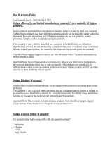
3.4 Board description
The FRDM-GD3100EVM Rev C is a half-bridge evaluation board populated with two
GD3100 single channel IGBT gate drive devices. The board supports connection to a
FRDM-KL25Z microcontroller for SPI communication and programming, through the use
of a logic translator board. The board includes circuitry to enable the many features of the
GD3100, such as IGBT short circuit detection and temperature sensing.
The evaluation board is designed to connect to a single phase of a Fuji M653 or M661
IGBT module for evaluation of the GD3100 performance and capabilities.
Figure 1. Assembled GD3100 half-bridge EVB, FRDM-KL25Z and translator board

NXP Semiconductors
UM11108
FRDM-GD3100EVM half-bridge evaluation board
UM11108 All information provided in this document is subject to legal disclaimers. © NXP B.V. 2020. All rights reserved.
User manual Rev. 5 — 10 February 2020
5 / 32
3.4.1 Low-voltage logic and controls connector
Low-voltage domain is 12 V VSUP/VPWR domain that interfaces with the MCU and
GD3100 control registers through the 24-pin connector interface.
Low-side driver and high-side driver domains are driver control interfaces to IGBT single
phase connections and test points.
Figure 2. Evaluation board voltage and interface domains
Table 2. Low-voltage (LV) domain 24-pin connector definitions
Pin Name Function
1 AOUTL Duty cycle encoded signal (low-side)
2 n.c. No connection
3 CSBL Chip select bar (low-side)
4 n.c. No connection
5 PWML PWM input (low-side)
6 INTBL Interrupt bar (low-side)
7 MOSIL Master out slave in (low-side)
8 SCLK Serial clock input
9 MISOL Master in slave out (low-side)
10 EN_PS Enable power supplies for VCC/VEE
11 FSSTATEL Fail-safe state (low-side)
12 GND Ground
13 FSENB Fail-safe enable (high-side and low-side)
14 MISOH Master in slave out (high-side)

NXP Semiconductors
UM11108
FRDM-GD3100EVM half-bridge evaluation board
UM11108 All information provided in this document is subject to legal disclaimers. © NXP B.V. 2020. All rights reserved.
User manual Rev. 5 — 10 February 2020
6 / 32
Pin Name Function
15 n.c. No connection
16 MOSIH Master out slave in (high-side)
17 n.c. No connection
18 CSBH Chip select bar (high-side)
19 LED_PWR 3.3 V supply for INTB LEDs (high-side and low-side)
20 AOUTH Duty cycle encoded signal (high-side)
21 PWMH PWM input (high-side)
22 FSSTATEH Fail-safe state (high-side)
23 GND Ground
24 INTBH Interrupt bar (high-side)
3.4.2 Test point definitions
All test points are clearly marked on the evaluation board. Figure 3 shows the location of
various test points.

NXP Semiconductors
UM11108
FRDM-GD3100EVM half-bridge evaluation board
UM11108 All information provided in this document is subject to legal disclaimers. © NXP B.V. 2020. All rights reserved.
User manual Rev. 5 — 10 February 2020
7 / 32
Figure 3. Key test point locations
Table 3. Driver board test point definitions
Test point Reference
designator
Definition
Low voltage (LV) domain
GND TP17, TP18, TP19,
TP20
Grounding points for low-voltage domain
VPWR TP3 DC voltage source connection point for VSUP power input of
GD3100 devices and flyback power supplies. Typically supplies by
vehicle battery +12 V DC, but can also be configured for +5 V DC
operation.
VSUPL TP47 Test point for VSUPL supply
VSUPH TP4 Test point for VSUPH supply
Low-side (LS) driver domain
AL TP24 Anode test point to thermal diode on low-side IGBT connection

NXP Semiconductors
UM11108
FRDM-GD3100EVM half-bridge evaluation board
UM11108 All information provided in this document is subject to legal disclaimers. © NXP B.V. 2020. All rights reserved.
User manual Rev. 5 — 10 February 2020
8 / 32
Test point Reference
designator
Definition
AMUXINL TP31 Test point for analog MUX input for low-side driver. Can be used for
monitoring DC bus voltage.
CLAMPL TP29 VCE sense test point connected to low-side driver clamp pin and
circuitry
DESATL TP28 VCE desaturation test point connected to low-side driver DESAT pin
and circuitry
FSISOL TP25 Initiate fail-safe state control from HV domain for low-side driver
GL TP26 Test point providing direct measurement of low-side IGBT gate
GNDL TP32, TP33, TP34 Isolated low-side driver ground point. Connected to low-side IGBT
emitter
ISENSEL TP27 ISENSE test point connected to IGBT current sense and GD3100
low-side driver sense pin
MMCX_GL J30 50 Ω connector (MMCX) providing direct measurement of low-side
IGBT gate
SL TP27 ISENSE test point close to IGBT current sense and connected to
low-side driver sense pin
TSENSEL TP36 Input for low-side IGBT temperature measurement. Onboard
components optimized for use with IGBT thermal diode.
VCCL TP21 Provides access to measure positive voltage supply powering HV
die and gate driver for low-side IGBT
VEEL TP30 Negative voltage supply test point for low-side driver gate of IGBT
VREFL TP22 Monitor internal 5.0 V reference for analog circuitry on HV isolated
die
High-side (HS) driver domain
AH TP6 Anode test point to thermal diode on high-side IGBT connection
AMUXINH TP13 Test point for analog MUX input for high-side driver
CLAMPH TP11 VCE sense test point connected to high-side driver clamp pin and
circuitry
DESATH TP10 VCE desaturation test point connected to high-side driver DESAT
pin and circuitry
FSISOH TP7 Initiate fail-safe state control from HV domain for high-side driver
GH TP8 Test point providing direct measurement of high-side IGBT gate
GNDH TP14, TP15, TP16 Isolated high-side driver ground point. Connected to high-side IGBT
emitter and low-side IGBT collector
ISENSEH TP9 ISENSE test point connected to IGBT current sense and GD3100
high-side driver sense pin
MMCX_GH J29 50 Ω connector (MMCX) providing direct measurement of high-side
IGBT gate
SH TP9 ISENSE test point close to IGBT current sense and connected to
high-side driver sense pin
TSENSEH TP35 Input for high-side IGBT temperature measurement. Onboard
components optimized for use with NTC
VCCH TP2 Provides access to measure positive voltage supply powering HV
die and gate driver for high-side IGBT
VREFH TP5 Monitor internal 5.0 V reference for analog circuitry on HV isolated
die
VEEH TP12 Negative voltage supply test point for high-side driver gate of IGBT

NXP Semiconductors
UM11108
FRDM-GD3100EVM half-bridge evaluation board
UM11108 All information provided in this document is subject to legal disclaimers. © NXP B.V. 2020. All rights reserved.
User manual Rev. 5 — 10 February 2020
9 / 32
3.4.3 Power related jumpers configuration
Figure 4. Power supply and jumpers configuration
Table 4. Power related jumper definitions
Jumper Reference
designator
Position Function
Open VCC regulator (VCCREG) active, gate driver (GH)
uses VCCREG (default)
VCCH J4
Closed VCC regulator (VCCREG) disabled, gate driver
(GH) uses VCC
1-2 VEE is negative supply (default)
2-3 VEE is tied to IGBT emitter (GNDISOH)
VEEH_SEL J5
Open Not allowed. VCC and VEE float relative to IGBT
emitter (GNDISOH)
Open VCC regulator (VCCREG) active, gate driver (GH)
uses VCCREG (default)
VCCL J7
Closed VCC regulator (VCCREG) disabled, gate driver
(GH) uses VCC
1-2 VEE is negative supply (default)
2-3 VEE is tied to IGBT emitter (GNDISOL)
VEEL_SEL J8
Open Not allowed. VCC and VEE float relative to IGBT
emitter (GNDISOL).
Open VSUP power to gate drive device must be supplied
at TP4
VSUPH J12
Closed Must be closed to supply VPWR to VSUP pin on
gate drive device (default)
Open VDD-VSUP are separate. Device powered from
VSUP, VDD uses internal regulator (default)
VDDH J13
Closed VDD-VSUP connected. VDD internal regulator
bypassed. Device powered by external 5.0 V.

NXP Semiconductors
UM11108
FRDM-GD3100EVM half-bridge evaluation board
UM11108 All information provided in this document is subject to legal disclaimers. © NXP B.V. 2020. All rights reserved.
User manual Rev. 5 — 10 February 2020
10 / 32
Jumper Reference
designator
Position Function
Open VDD-VSUP are separate. Device powered from
VSUP, VDD uses internal regulator (default)
VDDL J16
Closed VDD-VSUP connected. VDD internal regulator
bypassed. Device powered by external 5.0 V.
Open VSUP power to gate drive device must be supplied
at TP47
VSUPL J33
Closed Must be closed to supply VPWR to VSUP pin on
gate drive device (default)
The FRDM-GD3100EVM Rev C provides configurability for different gate driver power
architectures. Steps for some common configurations are summarized below. The
jumper functionalities are detailed in Table 4.
3.4.3.1 Configuring power delivery to GD3100
To configure GD3100 for 12 V power - open VDD, provide 12 V to VPWR connection
(default):
• Open VDDH (J13) jumper
• Open VDDL (J16) jumper
• Connect 12 V to VPWR (TP3)
To configure GD3100 for 5.0 V power - short VDD to VSUP, provide 5.0 V to VSUP
connection:
• Short VDDH (J13) jumper
• Short VDDL (J16) jumper
• Connect 5.0 V or 12 V to VPWR (TP3)
• To isolate VPWR and VSUP open jumper J33 and J12 and power VSUP from TP4 and
TP47
3.4.3.2 Configuring VEE for gate drive (GL)
To configure for negative VEE, provided by onboard Zener network (default):
• Connect VEEH_SEL (J5) jumper to 1-2
• Connect VEEL_SEL (J8) jumper to 1-2
• VEE for high-side provided by Zener (D9) and bias resistors (R26, R27)
• VEE for low-side provided by Zener (D8) and bias resistors (R24, R25)
To configure for VEE = 0 V, VEE tied to IGBT emitter:
• Connect VEEH_SEL (J5) jumper to 2-3
• Connect VEEL_SEL (J8) jumper to 2-3
• Tune VCC-VEE output voltage (high and low sides) with feedback resistor (R20)
3.4.3.3 Configuring VCC for gate drive (GH)
To utilize internal VCC regulator (VCCREG = ~15 V) for gate drive (default):
• Open VCCH (J4) jumper
• Open VCCL (J7) jumper
• Ensure VCCREG is fixed around 15 V above isolated GNDH, GNDL
To disable VCC regulator, drive gate directly from VCC:

NXP Semiconductors
UM11108
FRDM-GD3100EVM half-bridge evaluation board
UM11108 All information provided in this document is subject to legal disclaimers. © NXP B.V. 2020. All rights reserved.
User manual Rev. 5 — 10 February 2020
11 / 32
• Short VCCH (J4) jumper
• Short VCCL (J7) jumper
• Tune VCC-GNDx output voltage (high and low sides) with feedback resistor (R3)
3.4.4 Signal related jumpers and configuration
Figure 5. Signal related jumper locations
Table 5. Signal related jumper configurations
Jumper Reference
designator
Position Function
1-2 Separate CSBH and CSBL. Use for normal mode
(default)
2-3 CSBH and CSBL tied together. Use for daisy chain.
CSB J17
Open Not allowed. Only CSBL will be active, not
recommended for normal use.
Closed MOSIH is routed directly to MCU. Use for normal SPI
mode (default)
MOSI J19
Open MOSIH receives MISOL signal. Use for daisy-chain
SPI mode.
1-2 MCU/software controls VCC/VEE power supply
(default).
2-3 VCC/VEE power supplies always enabled. MCU
control signal is disconnected
PS_EN J20
Open Passive pulldown (R14) disables VCC/VEE power
supplies
1-2 PWMALTL receives complementary PWMH signal.
Enables dead time protection (default).
2-3 PWMALTL is grounded. Bypasses dead time control
(i.e. double-pulse, short-circuit test).
PWMALTL_
SEL
J21
Open Not allowed. PWMALTL is in an unknown state.
1-2 PWMALTH receives complementary PWML signal.
Enables dead time protection (default).
2-3 PWMALTH is grounded. Bypasses dead time control
(i.e. double-pulse, short-circuit test).
PWMALTH_
SEL
J22
Open Not allowed. PWMALTH is in an unknown state.

NXP Semiconductors
UM11108
FRDM-GD3100EVM half-bridge evaluation board
UM11108 All information provided in this document is subject to legal disclaimers. © NXP B.V. 2020. All rights reserved.
User manual Rev. 5 — 10 February 2020
12 / 32
Jumper Reference
designator
Position Function
1-2 MISOL is passed directly to MCU. Use for normal SPI
mode. (default)
2-3 MISOL is passed to MOSIH. Use for daisy-chain SPI
mode.
MISO J23
Open Not allowed. MISOL is not routed anywhere for valid
communication.
Short Solder shorting jumper to enable DC Link voltage
measurement to AMUXIN on low side gate drive
device.
Open, Default AMUXINL not connected to DC bus
voltage divider.
AMUXINL SJ1
Open AMUXINL not connected to DC bus voltage divider.
(default)
Closed TSENSEA pin and filter are connected to the module
temperature sense. Use when IGBT temperature
sense is available. (default)
TSNSH_EN J11
Open TSENSEA pin and filter are disconnected from the
module. Use when IGBT temperature sense is not
available. Suggest to disable TSENSE feature and
populate pull-up resistor to VREF.
Closed TSENSEA pin and filter are connected to the module
temperature sense. Use when IGBT temperature
sense is available. (default)
TSNSL_EN J10
Open TSENSEA pin and filter are disconnected from the
module. Use when IGBT temperature sense is not
available. Suggest to disable TSENSE feature and
populate pull-up resistor to VREF.
The FRDM-GD3100EVM Rev C provides configurability for accessing the GD3100 under
a few different controls schemes. Some common configurations are summarized below,
along with steps to adapt the driver board are described. The jumper functionalities are
detailed in Table 5.
3.4.4.1 SPI configuration options
To configure for normal SPI; low and high side GD3100s are addressable separately
(default):
• Set CSB (J17) jumper to 1-2
• Set MISO (J23) jumper to 1-2
• Short MOSI (J19) jumper
• From SPIGen, “SPI0” addresses low-side GD3100 (U4) with CSBL; use “SPI1” to
address high-side GD3100 (U3) with CSBH.
To configure both GD3100 in daisy-chain configuration:
• Set CSB (J17) jumper to 2-3
• Set MISO (J23) jumper to 2-3
• Open MOSI (J19) jumper
• From SPIGen, use “SPI0” to address both devices in daisy-chain configuration; “SPI1”
will be inactive.

NXP Semiconductors
UM11108
FRDM-GD3100EVM half-bridge evaluation board
UM11108 All information provided in this document is subject to legal disclaimers. © NXP B.V. 2020. All rights reserved.
User manual Rev. 5 — 10 February 2020
13 / 32
3.4.4.2 Configuring dead time application in hardware
To enable dead time and cross-conduction protection, PWMALT receives complimentary
signals (default):
• Set PWMALTH_SEL (J22) to 1-2
• Set PWMALTL_SEL (J21) to 1-2
To bypass dead time insertion (set PWMALT = 0) for specialized testing:
• Set PWMALTH_SEL (J22) to 2-3
• Set PWMALTL_SEL (J21) to 2-3
3.4.4.3 Setting method of power supply control (VCCx, VEEx)
VCC and VEE flyback controllers are always ON (default):
• Connect PS_EN (J20) jumper to 2-3
Allow control to turn VCC/VEE flyback supplies ON/OFF:
• Connect PS_EN (J20) jumper to 1-2
• Utilize Enable VCC/VEE on SPIGEN GUI to enable or disable the power supplies
3.4.5 Bottom view
Figure 6. GD3100 evaluation board bottom view
3.4.6 Gate drive resistors
• RGH - gate high resistor in series with the GH pin at the output of the GD3100 high-
side driver and IGBT gate that controls the turn-on current for IGBT gate.
• RGL - gate low resistor in series with the GL pin at the output of the GD3100 low-side
driver and IGBT gate that controls the turn-off current for IGBT gate.

NXP Semiconductors
UM11108
FRDM-GD3100EVM half-bridge evaluation board
UM11108 All information provided in this document is subject to legal disclaimers. © NXP B.V. 2020. All rights reserved.
User manual Rev. 5 — 10 February 2020
14 / 32
• RAMC - series resistor between IGBT gate and AMC input pin of the GD3100 high-
side/low-side driver for gate sensing and Active Miller clamping.
Figure 7. Gate drive resistors
3.4.7 LED interrupt indicators
Interrupt LEDs are provided to visually alert the user of a reported fault. The LEDs
are supplied with 3.3 V from the KL25Z, and are driven directly by the INTB pin of the
respective GD3100 device.
• D3 (INTBH) LED is ON while fault is being reported (INTB low). LED is OFF while no
fault is reported (INTB high).
• D2 (INTBL) LED is ON while fault is being reported. LED is OFF while no fault is
reported (INTB high).
Figure 8. LED interrupt indicators

NXP Semiconductors
UM11108
FRDM-GD3100EVM half-bridge evaluation board
UM11108 All information provided in this document is subject to legal disclaimers. © NXP B.V. 2020. All rights reserved.
User manual Rev. 5 — 10 February 2020
15 / 32
Table 6. Interrupt LED definitions
LED Reference
designator
Description
Low-side INTB D2 Connected to the INTB output pin (active low) of low-side
GD3100
• LED is ON: indicates reported fault, check system
• LED is OFF: indicates no reported fault
High-side INTB D3 Connected to the INTB output pin (active low) of high-side
GD3100
• LED is ON: indicates reported fault, check system
• LED is OFF: indicates no reported fault
3.5 Kinetis KL25Z freedom board
The Freedom KL25Z is an ultra-low-cost development platform for Kinetis
®
L Series
MCU built on Arm
®
Cortex
®
-M0+ processor.
Figure 9. Freedom Development Platform
3.6 Logic translator board
The FRDM-GD3100EVM Rev C includes a logic translator board, which provides simple
isolation and is capable of level-shifting communication signals between the MCU and
the GD3100 driver board. The driver board is exposed to high voltage, and may require
3.3 V or 5.0 V logic, necessitating an interface board.
Various signals, like the SPI communication, interrupt, fail-safe controls, and PWM pass
through the translator board. The translator board provides a configurable output voltage
(3.3 V or 5.0 V) going out to the GD3100 driver board.
The translator board also provides the choice of using PWM signals from the MCU,
or wiring in an external control from a function generator. Jumper configurations are
explained in Figure 10 and Table 7. Test points are reviewed in Table 8.

NXP Semiconductors
UM11108
FRDM-GD3100EVM half-bridge evaluation board
UM11108 All information provided in this document is subject to legal disclaimers. © NXP B.V. 2020. All rights reserved.
User manual Rev. 5 — 10 February 2020
16 / 32
Figure 10. Logic translator board
Table 7. Translator board jumper functionality
Jumper Reference
designator
Position Function
1-2 5.0 V regulator from KL25Z powers all translator VCC,
5.0 V signals to/from the driver board (default)
• Use with 5.0 V GD3100 (MC33GD3100EK)
2-3 3.3 V regulator from KL25Z powers all translator VCC,
3.3 V signals to/from the driver board
• Use with 3.3 V version of GD3100
(MC33GD3100A3EK)
VCCSEL J233
Open Not allowed. There is no power provided to logic
translators, and no signals will be passed to the driver
board.
• Provide external power to J233, pin 2 (max 5.5 V)
to enable communications
Closed PWMH signal from MCU is passed to the driver board
(default)
PWMH J235
Open External signal for PWMH must be provided at EXT_
PWMH (TP11)
Closed PWML signal from MCU is passed to the driver board
(default)
PWML J236
Open External signal for PWML must be provided at EXT_
PWML (TP10)
Table 8. Translator board test point definition
Test point Reference designator Definition
EXT_PWML TP10 PWML signal provided to driver board
EXT_PWMH TP11 PWMH signal provided to driver board
GND TP12 GND connection for translator, also connected to GND on
LV domain of driver board

NXP Semiconductors
UM11108
FRDM-GD3100EVM half-bridge evaluation board
UM11108 All information provided in this document is subject to legal disclaimers. © NXP B.V. 2020. All rights reserved.
User manual Rev. 5 — 10 February 2020
17 / 32
The translator board in FRDM-GD3100EVM Rev C supports different configurations
for various application tests. The translator supports PWM from either the KL25Z (see
Section 3.6.1 "Configuring the translator for KL25Z-controlled PWM") or from external
source (see Section 3.6.2 "Configuring the translator for external PWM control"), one of
these implementations will be used in testing. Similarly, based on the GD3100 device
populated, the translator will need to support either 5.0 V logic (see Section 3.6.3
"Configuring the translator for 5.0 V logic operation") or 3.3 V logic (see Section 3.6.4
"Configuring the translator for 3.3 V logic operation").
3.6.1 Configuring the translator for KL25Z-controlled PWM
By default, the translator is setup to send PWM signals generated on the KL25Z out
to the driver board. These signals pass through the translator and are level-shifted
according to the translator’s own configuration. Test points EXT_PWML (TP10) and
EXT_PWMH (TP11) are available to monitor commanded PWM state.
To configure the translator board for KL25Z-controlled PWM, perform the following:
1. Short PWMH (J235) jumper.
2. Short PWML (J236) jumper.
3. Use SPIGen to apply double-pulse, short-circuit, or PWM waveforms.
3.6.2 Configuring the translator for external PWM control
The translator may be setup to pass externally provided signals to the driver board,
normally applied at EXT_PWML (TP10) and EXT_PWMH (TP11) test points. These
signals do not pass through the translator, so their logic level must match those required
by the GD3100 populated on the driver board.
To configure the translator board for external PWM control, perform the following:
1. Open PWMH (J235) jumper.
2. Open PWML (J236) jumper.
3. Apply desired PWM function between EXT_PWML (TP10) and GND (TP12).
4. Apply desired PWM function between EXT_PWMH (TP11) and GND (TP12).
3.6.3 Configuring the translator for 5.0 V logic operation
This configuration is for use with the 5.0 V gate driver device (MC33GD3100EK)
populated on the driver board. The attached KL25Z has a 5.0 V supply (drawn from USB
power bus) that is pinned out to the translator for this purpose.
To configure the translator board to send/receive 5.0 V logic level signals, perform the
following:
1. Set VCCSEL (J233) jumper to 1-2.
3.6.4 Configuring the translator for 3.3 V logic operation
This configuration is for use with the 3.3 V gate driver device (MC33GD3100A3EK)
populated on the driver board. The attached KL25Z has a 3.3 V regulator onboard that is
pinned out to the translator for this purpose.
To configure the translator board to send/receive 3.3 V logic level signals, perform the
following:
1. Set VCCSEL (J233) jumper to 2-3.

NXP Semiconductors
UM11108
FRDM-GD3100EVM half-bridge evaluation board
UM11108 All information provided in this document is subject to legal disclaimers. © NXP B.V. 2020. All rights reserved.
User manual Rev. 5 — 10 February 2020
18 / 32
4 Configuring the hardware
4.1 System setup
FRDM-GD3100EVM Rev C is connected to any phase of an Fuji Electric M653 or
M661 IGBT module with SBE DC Link capacitor as shown in Figure 11. Double pulse
and short-circuit testing can be conducted utilizing Windows based PC with SPIGEN
software.
Suggested equipment needed for testing:
• Rogowski coil high current probe
• High voltage differential voltage probe
• High sample rate digital oscilloscope with probes
• DC link capacitor
• Fuji Electric M653 or M661 IGBT module
• Windows 10, 8 or 7 compatible PC with an available USB port
• High voltage DC power supply for DC link
• Low voltage DC power supply for VSUP/GD3100PWR
• +12 V DC gate drive board low voltage domain
• Voltmeter for monitoring high voltage DC Link supply
• Load coil for double pulse and short-circuit type 2 testing
Figure 11. Evaluation board and system setup

NXP Semiconductors
UM11108
FRDM-GD3100EVM half-bridge evaluation board
UM11108 All information provided in this document is subject to legal disclaimers. © NXP B.V. 2020. All rights reserved.
User manual Rev. 5 — 10 February 2020
19 / 32
4.2 Quick start
4.2.1 Scope and purpose
This section provides comprehensive quick start notes for the FRDM-GD3100EVM Rev
C half-bridge evaluation kit. Within a few minutes the user can install SPIGEN application
on a PC, power up the half-bridge evaluation kit, start SPI communication, and pass
PWM signals to evaluate working operation.
4.2.2 Intended audience
Experienced engineers evaluating GD3100 gate drive device for IGBT control.
4.2.3 Setting up and connecting the evaluation kit
1. Download and Install latest SPIGEN software – Windows application from NXP.com
to your PC (see Section 5.2 "Configuring the FRDM-KL25Z microcode").
2. Assemble the FRDM-GD3100EVM Rev C with KL25Z micro board and translator
board as shown in Figure 1.
3. Check jumper configuration on the evaluation board before powering up, and ensure
the configuration meets desired use case.
a. The default jumper configuration (shipped from factory) is setup normal SPI (non-
daisy chain) communication with high-side and low-side driver domains VEE
negative supply level active. Also, ensure jumper J233 is populated on Translator
board for powering KL25Z micro.
b. For alternate configurations and setup details, see Section 3.4.3, Section 3.4.4
"Signal related jumpers and configuration", and Section 3.4.7 "LED interrupt
indicators".
4. Start SPIGEN application software on PC. Connect USB cable from PC to USBKL25Z
port on KL25Z micro board. A successful connection results in a connection
successful pop-up (reading "SPI dongle is connected") on the PC with SPIGEN
application running.
a. KL25Z micro shipped with proper firmware is already flashed. See Section 5
"Installation and use of software tools" for additional details.
5. Next supply 12 V DC power to low voltage domain of evaluation board (12 V DC
to VSUP connection point and grounding to GND1 connection point on low voltage
domain).
6. Check high-side and low-side driver domain regulated voltage level by checking
VCCH and VCCL test points for ~17 V DC with respect to grounding to points GNDH
and GNDL in each domain respectively.
a. If voltage level on VCCH and VCCL are low adjust R3 potentiometer for proper
level as shown in Figure 4.
7. With proper PC interface connection and voltage levels, SPI communication can be
conducted with GD3100 devices over SPIGen as described in Section 5.3 "Using the
SPIGEN graphical user interface". See GD3100 data sheet for additional details.
a. Selecting SPI0 communicates with low-side gate drive device and SPI1
communicates with high-side gate drive device (see Figure 13).
8. Apply PWM signals to each gate drive. Gate drive output can be observed on high-
side and low-side driver devices with test points (GH, GL), or 50 Ω port (MMCX GATE
H/L).

NXP Semiconductors
UM11108
FRDM-GD3100EVM half-bridge evaluation board
UM11108 All information provided in this document is subject to legal disclaimers. © NXP B.V. 2020. All rights reserved.
User manual Rev. 5 — 10 February 2020
20 / 32
a. To receive PWM as provided by the KL25Z, see Section 3.6.1 "Configuring the
translator for KL25Z-controlled PWM". Use SPIGen to control, see Section 5.3.4
"Pulse test".
b. b. To set up for external PWM control, see Section 3.6.2 "Configuring the translator
for external PWM control". Apply a control signal with an external function
generator.
9. For double pulse and short-circuit testing with an IGBT and inductive load, use
the "Pulse test" view as part of the SPIGen GUI. Set parameterized pulse widths
commanded by the KL25Z.
a. For short-circuit testing, PWMALTL_SEL and PWMALTH_SEL must be configured
so as to bypass dead time control (see Section 3.4.4.2 "Configuring dead time
application in hardware").
5 Installation and use of software tools
Software for FRDM-GD3100EVM Rev C is distributed with the SPIGen GUI tool
(available on NXP.com). Necessary firmware comes pre-installed on the FRDM-KL25Z
with the kit.
Even if the user intends to test under other software or PWM, it is recommended the user
install this software below as a backup or in help debugging.
Figure 12. FRDM-KL25Z setup and interface
5.1 Installing SPIGen on your computer
The latest version of SPIGen supports the GD3100 and is designed to run on any
Windows 10, Windows 8, or Windows 7-based operating system. To install the software,
do the following:
1. Go to www.nxp.com/SPIGen and click Download.
2. When the SPIGEN: SPI Generator (SPIGen) software page appears, go to the
Lab and Test Software section and click Download associated with the description
of the selected environment. A wizard guides the user through the process.
3. If instructed for the SPIGen wizard to create a shortcut, a SPIGen icon appears on
the desktop. By default, the SPIGen executable file is installed at C:\Program Files
(x86)\SPIGen.
/