Page is loading ...

Adjustable Clamping Work Table
OPERATOR’S MANUAL
To Reduce The Risk Of Injury, User Must Read And
Understand Operator’s Manual. Save These Instructions For Future Reference.
CAUTION:
© 2016 Menard, Inc., Eau Claire, WI 54703
240-1579

Reference this manual for all safety warnings and precautions, operating and maintenance
procedures, parts list and diagrams. Keep your invoice with this manual and write your invoice
number on the inside of the front cover. Keep the manual and invoice in a safe, dry place for
future reference.
Save this Manual..............................................................................
Safety ...............................................................................................
Parts List...........................................................................................
Assembly Instructions......................................................................
Functions..........................................................................................
Warran-
Page 1
Page 1
Page 2
Page 3
Page 5
Page 6
Be sure to read and understand all safety instructions in this manual,
including all safety alert symbols such as "danger'', "warning", and "caution" before using
this tool. This vise can create nearly 2.5 tons of clamping force! Failure to follow all
instructions may result in serious personal injury.
WARNING:
TABLE OF CONTENTS
SAVE THIS MANUAL
Page 6Page 1
SAVE YOUR RECEIPTS
THIS WARRANTY IS VOID WITHOUT THEM
90-DAY MONEY BACK GUARANTEE
WARRANTY
This MASTERFORCE® brand tool carries our 90-Day Money Back Guarantee.
If you are not completely satisfied with your MASTERFORCE® brand power tool for
any reason within ninety (90) days from the date of purchase, return the tool with your
original receipt to any MENARDS® retail store, and we will provide you a refund - no
questions asked.
Adjustable Clamping Work Table
Using power tools of any kind can be dangerous if safe operating procedures are not followed.
Recognizing the hazards of each tool and using them with respect and caution will considerably
limit the possibility of personal injury. However, if safety precautions are ignored, personal injury
will likely result. Always use common sense - your personal safety is your responsibility.
1. Know your power tool. Read and understand the Operator's Manual and observe the
warnings and instruction labels affixed to the tool.
2. Properly ground all tools.
3. Keep guards in place.
4. Remove adjusting keys and wrenches.
5. Keep work area clean and dry.
6. Keep children away.
7. Never leave running machines/tools unattended.
8. Disconnect tools from service.
9. Use correct tools for the job.
10. Never force a tool.
11. Wear safety apparel.
12. Wear safety glasses/goggles.
13. Never stand or sit on tools.
14. Replace damaged components immediately.
SAFETY
3-YEAR LIMITED WARRANTY
This MASTERFORCE
®
brand tool carries our famous No Hassle 3-Year Limited
Warranty to the original purchaser. If, during normal use, this MASTERFORCE
®
power
tool breaks or fails due to a defect in material or workmanship, simply bring the tool with
the original sales receipt back to your nearest MENARDS
®
retail store. At its discretion,
MASTERFORCE
®
agrees to have the tool or any defective part(s) repaired or replaced
with the same or similar MASTERFORCE
®
product or part free of charge, within the
stated warranty period, when returned by the original purchaser with original sales
receipt. Not withstanding the foregoing, this 3-year limited warranty does not cover any
damage that has resulted from abuse or misuse of the Merchandise. This warranty: (1)
excludes expendable parts including but not limited to blades, brushes, belts, bits, light
bulbs, and/or batteries; (2) shall be void if this tool is used for commercial and/or rental
purposes; and (3) does not cover any losses, injuries to persons/property or costs. This
warranty does give you specific legal rights and you may have other rights, which vary
from state to state. Be careful, tools are dangerous if improperly used or maintained.
Seller’s employees are not qualified to advise you on the use of this merchandise. Any
oral representation(s) made will not be binding on seller or its employees. The rights
under this 3-year limited warranty are to the original purchaser of the merchandise and
may not be transferred to any subsequent owner. This 3-year limited warranty is in lieu
of all warranties, expressed or implied including warranties or merchantability and fitness
for a particular purpose. Seller shall not be liable for any special, incidental, or
consequential damages. The sole exclusive remedy against the seller will be for the
replacement of any defects as provided herein, as long as the seller is willing or able to
replace this product or is willing to refund the purchase price as provided above. For
insurance purposes seller is not allowed to demonstrate any of these power tools for you.
For questions / comments, technical assistance or repair parts -
Please call toll free at: 1-800-255-7011 (M-F 8am - 6pm CST)

Page 2Page 5
PARTS LIST
FUNCTIONS
Height Adjustment (seven levels).
a. Turn the height adjustment knobs counter-clockwise on each leg to loosen (fig. 1).
b. Push the elevating swing bar back with your foot to disengage the two hooks and adjust
the height of the bench upwards (fig. 2) or downwards (fig. 3).
c. Use the elevating swing bar to ensure the two hooks are re-engaged into the two elevating
rods’ adjustment holes.
d. Turn the height fixing knobs clockwise on each leg to tighten (fig. 4). Note: Ensure the
height fixing knobs are tight before using the workbench.
Tilt Angle Adjustment (four levels).
a. For normal use, the bench top will be set horizontal, however the top can also be adjusted
to 25°, 50° and 80°.
b. Ensure that the tilt adjustment knobs are completely unscrewed.
c. Push the two adjustment knobs in simultaneously and tilt the bench top until the knobs
engage into the next set of preset guide holes (fig. 5).
d. Turn the tilt adjustment knobs clockwise to tighten the bench top and hold the desired
position.
Bench Top Adjustment
a. To adjust the bench top, pull up both levers on each sliding bar and slide forwards or
backwards as desired (fig. 6).
b. Ensure that the mechanism is securely engaged in the holes in both sliding bars.
c. The support table extension arms can be swung in and out of position to best suit the
needs of the work piece being held in place (fig.7).
Note: Ensure the tilt adjustment knobs are tight before using the workbench. Use the
preset guide holes only.
1
2 3
4
6
7
5
SMALL TABLE DOG
LEG FEET
M6X35 BOLT
M6X12 BOLT
M6 NYLON NUT
M6 WASHER
1 pcs
2 pcs
1 pcs
1 pcs
4 pcs
2 pcs
1
2
3
4
5
6
4 pcs
4 pcs
4 pcs
4 pcs
8 pcs
8 pcs
7
8
9
10
11
12
PART # DESCRIPTION QTY
PART # DESCRIPTION QTY
BENCH TOP WITH SLIDING BAR
ELEVATING ROD WITH TILT ADJUSTER
CROSS BAR
LEG FRAME
LARGE TABLE DOG
HEIGHT FIX KNOB
8
9
10
11
12
15. Make sure your work platform is sufficiently sturdy to do the specific job at hand
16. Properly anchor blade for job being done.
17. Use correct blade for job being done.
18. Think Safety. Safety is a combination of operator awareness, common sense and
alertness at all times.
SAFETY
FIG 1
FIG 2
FIG 3
FIG 4
FIG 5 FIG 6 FIG 7

ASSEMBLY INSTRUCTIONS ASSEMBLY INSTRUCTIONS
Page 3
Page 4
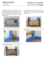
1. Attach four leg feet (8) to the leg frame (4).
2. Attach cross bar (3) to the two elevating rods (2) with M6 x 35 hex bolts (9), M6 Nylon
nuts (11) and M6 washers (12). Make sure the seven pre-drilled holes on both elevating rods
are on the opposite side and the adjusting knobs are on the outside of the assembly.
3. Push the elevating swing bar backwards and insert the elevating rod assembly into the frame
tubes ensuring that the latches on the swing rods fit into the holes on the elevating rods.
4. Use height fix knob(6) to tighten elevating rod (2) to keep the safe situation.
5. Lay the bench top (1) onto the top of the elevating rod assembly. Ensure the frame of the
bench top sits outside the tops of the legs. Attach using M6 x 12 bolts (10), M6 safety hex
nuts (11) and M6 washers (12).
6. The Table dog (5) can be inserted into the top channels. Pull the Table dog (5) up and turn it
around to adjust the angle of the clamp, as required.
7. The small table dog (7) can be inserted into the side channels, as required.
1
2
5
4
8
6
3
7
10
12
11
x2
x2
x2
3
4
/