Hitachi DH24PH Handling Instructions Manual
- Category
- Rotary hammers
- Type
- Handling Instructions Manual

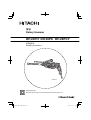
DH28PCY
Rotary Hammer
DH 24PH
•
DH 26PC
•
DH 28PCY
Handling instructions
Read through carefully and understand these instructions before use.

2
12
34
56
78
1
2
8
7
3
4
4
5
4
6
9
8
9

3
910
11 12
13 14
15 16
3
4
0
#
@
!
4
3
$
*
4
4
)
&
(
^
3
*
%
1
2
8
9
8 9

4
17 18
19 20
21
w
q
w
q
e
t
y
r

5
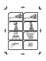
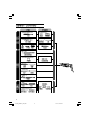
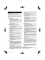
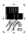
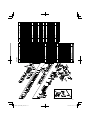
1
Drill bit
2
Part of SDS-plus shank
3
Front cap
4
Grip
5
Dust cap
6
Dust collector (B)
7
Push button
8
Change lever
9
Push button
0
Drill chuck
!
Chuck adapter
@
Chuck adapter (D)
#
Bit
$
Socket
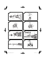
%
Side handle
^
Depth gauge
&
Mounting hole
*
Taper shank adapter
(
Cotter
)
Rest
q
Core bit
w
Core bit shank
e
Thread
r
Center pin
t
Guide plate
y
Core bit tip
Symbols
WARNING
The following show symbols used for the machine. Be
sure that you understand their meaning before use.
To reduce the risk of injury, user must read instruction
manual.

6
13.5.15, 9:07 AM6

7
13.5.15, 9:08 AM7

8
+
+ +
(13 VLRB-D)
, -
13.5.15, 9:08 AM8

9
*
13.5.15, 9:08 AM9

10
13.5.15, 9:08 AM10

11
13.5.15, 9:08 AM11

12
13.5.15, 9:08 AM12

13
GENERAL POWER TOOL SAFETY WARNINGS
WARNING
Read all safety warnings and all instructions.
Failure to follow the warnings and instructions may result in
electric shock, fi re and/or serious injury.
Save all warnings and instructions for future reference.
The term “power tool” in the warnings refers to your mains-
operated (corded) power tool or battery-operated (cordless)
power tool.
1) Work area safety
a) Keep work area clean and well lit.
Cluttered or dark areas invite accidents.
b) Do not operate power tools in explosive
atmospheres, such as in the presence of
fl ammable liquids, gases or dust.
Power tools create sparks which may ignite the dust
or fumes.
c) Keep
children and bystanders away while
operating a power tool.
Distractions can cause you to lose control.
2) Electrical safety
a) Power tool plugs must match the outlet.
Never modify the plug in any way.
Do not use any adapter plugs with earthed
(grounded) power tools.
Unmodifi ed plugs and matching outlets will reduce
risk of electric shock.
b) Avoid body contact with earthed or grounded
surfaces, such as
pipes, radiators, ranges and
refrigerators.
There is an increased risk of electric shock if your
body is earthed or grounded.
c) Do not expose power tools to rain or wet
conditions.
Water entering a power tool will increase the risk of
electric shock.
d) Do not abuse the cord. Never use the cord for
carrying, pulling or unplugging the power tool.
Keep cord away from heat, oil, sharp edges or
moving parts.
Damaged or entangled cords increase the risk of
electric shock.
e) When operating a
power tool outdoors, use an
extension cord suitable for outdoor use.
Use of a cord suitable for outdoor use reduces the
risk of electric shock.
f) If operating a power tool in a damp location
is unavoidable, use a residual current device
(RCD) protected supply.
Use of an RCD reduces the risk of electric shock.
3) Personal safety
a) Stay alert, watch what you are doing and use
common sense when operating a power tool.
Do not use a power tool while you are tired or under
the infl uence of drugs, alcohol or medication.
A moment of inattention while operating power tools
may result in serious personal injury.
b) Use personal protective equipment. Always
wear eye protection.
Protective equipment such as dust mask, non-skid
safety shoes, hard hat, or hearing protection used for
appropriate conditions will reduce personal injuries.
c) Prevent unintentional starting. Ensure the
switch is in the off position before connecting to
power source and/or
battery pack, picking up or
carrying the tool.
Carrying power tools with your fi nger on the switch or
energising power tools that have the switch on invites
accidents.
d) Remove any adjusting key or wrench before
turning the power tool on.
A wrench or a key left attached to a rotating part of the
power tool may result in personal injury.
e) Do not overreach. Keep proper footing and
balance at all times.
This enables better control of the power tool in
unexpected situations.
f) Dress properly. Do not wear loose clothing or
jewellery. Keep your hair, clothing and
gloves
away from moving parts.
Loose clothes, jewellery or long hair can be caught in
moving parts.
g) If devices are provided for the connection of
dust extraction and collection facilities, ensure
these are connected and properly used.
Use of dust collection can reduce dust related
hazards.
4) Power tool use and care
a) Do not force the power tool. Use the correct
power tool for your application.
The correct power tool will do the job better and safer
at the rate for which it was designed.
b) Do
not use the power tool if the switch does not
turn it on and off .
Any power tool that cannot be controlled with the
switch is dangerous and must be repaired.
c) Disconnect the plug from the power source and/
or the battery pack from the power tool before
making any adjustments, changing accessories,
or storing power tools.
Such preventive safety measures reduce the risk of
starting the power tool accidentally.
d) Store idle power tools out
of the reach of children
and do not allow persons unfamiliar with the
power tool or these instructions to operate the
power tool.
Power tools are dangerous in the hands of untrained
users.
e) Maintain power tools. Check for misalignment or
binding of moving parts, breakage of parts and
any other condition that may aff ect the power
toolsʼ
operation.
If damaged, have the power tool repaired before
use.
Many accidents are caused by poorly maintained
power tools.
f) Keep cutting tools sharp and clean.
Properly maintained cutting tools with sharp cutting
edges are less likely to bind and are easier to control.
g) Use the power tool, accessories and tool bits
etc. in accordance with these instructions,
taking into account the working conditions and
the work to be performed.
Use of the power tool for operations diff erent from
those intended could result in a hazardous situation.
5) Service
a) Have
your power tool serviced by a qualifi ed repair
person using only identical replacement parts.
This will ensure that the safety of the power tool is
maintained.
PRECAUTION
Keep children and infi rm persons away.
When not in use, tools should be stored out of reach of
children and infi rm persons.

14
ROTARY HAMMER SAFETY WARNINGS
1. Wear ear protectors.
Exposure to noise can cause hearing loss.
2. Use auxiliary handle(s), if supplied with the tool.
Loss of control can cause personal injury.
3. Hold power tool by insulated gripping surfaces,
when performing an operation where the cutting
accessory may contact hidden wiring or its own
cord. Cutting
accessory contacting a “live” wire may
make exposed metal parts of the power tool “live” and
could give the operator an electric shock.
4. Do not touch the bit during or immediately after operation.
The bit becomes very hot during operation and could
cause serious burns.
5. Before starting to break,
chip or drill into a wall, fl oor or
ceiling, thoroughly confi rm that such items as electric
cables or conduits are not buried inside.
6. Always hold the body handle and side handle of the
power tool fi rmly. Otherwise the counterforce produced
may result in inaccurate and even dangerous operation.
7. Wear
a dust mask.
Do not inhale the harmful dusts generated in drilling or
chiseling operation. The dust can endanger the health of
yourself and bystanders.
SPECIFICATIONS
Model DH24PH DH26PC DH28PCY
Voltage (by areas)* (110 V, 115 V, 120 V, 127 V, 220 V, 230 V, 240 V)
Power input* 730 W 830 W 850 W
No-load speed 0 – 1050 /min 0 – 1100 /min
Full-load speed rate 0 – 3950 /min 0 – 4300 /min
Capacity: concrete
steel
wood
3.4 – 24 mm
13 mm
32 mm
3.4 – 26 mm
13 mm
32 mm
3.4 – 28 mm
13 mm
32 mm
Weight (without cord) 2.7 kg 2.8 kg 2.9 kg
* Be sure to
check the nameplate on product as it is subject to change by areas.
STANDARD ACCESSORIES
(1) Plastic case ...................................................................1
(2) Side handle ...................................................................1
(3) Depth gauge .................................................................1
Standard accessories are subject to change without notice.

15
+
+
+
OPTIONAL ACCESSORIES (sold separately)
Drill bit
●
Drilling holes in concrete or tile
Taper shank
adapter
Cotter
Guide plate Center pin Core bit
Core bit shank
● Large hole boring
● Anchor setting
Anchor setting adapter
● Bolt placing operation with
Chemical Anchor
Chemical anchor adapter
Chuck
adapter
Drill chuck
(13 VLRB-D)
Special
screw
● Demolishing operation
Dust cup
Dust collector (B)
Rotation only Hammering only Rotation + Hammering
● Drilling anchor holes
● Groove digging and edging
● Grooving
● Driving screws
● Drilling in steel or wood
+
Driver bit
–
Driver bit
Drill bit for steel Drill bit for
wood
Grooving chisel
Cold chisel Cutter
Hexagon socket
Bull point
(Square type)
Bull point
(Round type)
Drill bit (Taper shank)
Tool Adapters
Use on jobs facing upwards

16
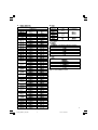
● Drilling holes in concrete or tile
Drill bit (slender shaft)
Outer dia. Overall length Eff ective length
3.4 mm
90 mm 45 mm
3.5 mm
SDS-plus Drill bit
Outer dia. Overall length Eff ective length
4.0 mm 110 mm 49 mm
5.0 mm
110 mm 49 mm
160 mm 99 mm
5.5 mm 110 mm 50 mm
6.0 mm
110 mm 50 mm
160 mm 100 mm
6.4 mm 160 mm 100 mm
6.5 mm 160 mm 100 mm
7.0 mm 160 mm 100 mm
7.5 mm 160 mm 100 mm
8.0 mm 160 mm 100 mm
8.5 mm 160 mm 100 mm
9.0 mm 160
mm 100 mm
9.5 mm 160 mm 100 mm
10.0 mm
160 mm 100 mm
260 mm 200 mm
10.5 mm
160 mm 100 mm
260 mm 200 mm
11.0 mm 160 mm 100 mm
12.0 mm
160 mm 88 mm
260 mm 187 mm
12.5 mm
160 mm 88 mm
260 mm 187 mm
12.7 mm
160 mm 88 mm
260 mm 187 mm
13.0 mm 160 mm 87 mm
14.0 mm 160 mm 87 mm
14.3 mm
160
mm 87 mm
260 mm 186 mm
14.5 mm
160 mm 87 mm
260 mm 186 mm
15.0 mm 160 mm 85 mm
16.0 mm
160 mm 85 mm
260 mm 186 mm
16.5 mm 160 mm 85 mm
17.0 mm
160 mm 85 mm
260 mm 185 mm
17.5 mm
160 mm 90 mm
260 mm 185 mm
18.0 mm 160 mm 85 mm
19.0 mm 260 mm 185 mm
20.0 mm 260 mm 175 mm
22.0 mm 260 mm 175
mm
24.0 mm 250 mm 173 mm
25.0 mm 450 mm 375 mm
● Large hole boring
Core bit
Outer dia.
Center pin
Core bit shank
Overall length
25 mm*
Not applicable
105 mm
300 mm
29 mm*
32 mm
(A)35 mm
38 mm
45 mm
(B) 300 mm
50 mm
* Without guide plate
● Anchor setting
Anchor setting adapter
Anchor size
W 1/4"
W 5/16"
W 3/8"
W 1/2"
W 5/8"
● Drilling anchor holes
Taper shank adapter
Taper mode
Morse taper No. 1
Morse taper No. 2
A-Taper
B-Taper
Optional accessories are subject to change without notice.

17
APPLICATIONS
Rotation and hammering function
○ Drilling anchor holes
○ Drilling holes in concrete
○ Drilling holes in tile
Rotation only function
○ Drilling in steel or wood
(with optional accessories)
○ Tightening machine screws, wood screws
(with optional accessories)
Hammering only function
○ Light-duty chiselling of concrete, groove digging and
edging.
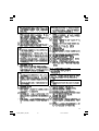
PRIOR TO OPERATION
1. Power source
Ensure that the power source to be utilized conforms
to the power requirements specifi ed on the product
nameplate.
2. Power switch
Ensure that the power switch is in the OFF position. If
the plug is connected to a power receptacle while the
power switch is in the
ON position, the power tool will
start operating immediately, which could cause a serious
accident.
3. Extension cord
When the work area is removed from the power source,
use an extension cord of suffi cient thickness and rated
capacity. The extension cord should be kept as short as
practicable.
4. Mounting
the drill bit (Fig. 1)
CAUTION
To prevent accidents, make sure to turn the switch off
and disconnect the plug from the receptacle.
NOTE
When using tools such as bull points, drill bits, etc.,
make sure to use the genuine parts designated by our
company.
(1) Clean the shank portion of the drill
bit.
(2) Insert the drill bit in a twisting manner into the tool holder
until it latches itself (Fig. 1).
(3) Check the latching by pulling on the drill bit.
(4) To remove the drill bit, fully pull the grip in the direction of
the arrow and pull out the drill
bit (Fig. 2).
5. Installation of dust cup or dust collector (B)
(Optional accessories) (Fig. 3, Fig. 4)
When using a rotary hammer for upward drilling
operations attach a dust cup or dust collector (B) to
collect dust or particles for easy operation.
○ Installing the dust cup
Use the dust
cup by attaching to the drill bit as shown in
Fig. 3.
When using a bit which has big diameter, enlarge the
center hole of the dust cup with this rotary hammer.
○ Installing dust collector (B)
When using dust collector (B), insert dust collector (B)
from the tip of
the bit by aligning it to the groove on the
grip (Fig. 4).
CAUTION
○ The dust cup and dust collector (B) are for exclusive use
of concrete drilling work. Do not use them for wood or
metal drilling work.
○ Insert dust collector (B) completely into the chuck part of
the
main unit.
○ When turning the rotary hammer on while dust collector
(B) is detached from a concrete surface, dust collector
(B) will rotate together with the drill bit. Make sure to turn
on the switch after pressing the dust cup on the concrete
surface. (When using dust collector (B) attached to
a
drill bit that has more than 190 mm of overall length,
dust collector (B) cannot touch the concrete surface and
will rotate. Therefore please use dust collector (B) by
attaching to drill bits which have 166 mm, 160 mm, and
110 mm overall length.)
○ Dump particles after every two or
three holes when
drilling.
○ Please replace the drill bit after removing dust collector
(B).
6. Selecting the driver bit
Screw heads or bits will be damaged unless a bit
appropriate for the screw diameter is employed to drive
in the screws.
7. Confi rm the direction of bit rotation (Fig.
5)
The bit rotates clockwise (viewed from the rear side) by
pushing the R-side of the push button.
The L-side of the push button is pushed to turn the bit
counterclockwise.
HOW TO USE
CAUTION
To prevent accidents, make sure to turn the switch off
and disconnect the plug from the receptacle when the
drill bits and other various parts are installed or removed.
The power switch should also be turned off during a work
break and after work.
1. Switch operation
The rotation
speed of the drill bit can be controlled
steplessly by varying the amount that the trigger switch
is pulled. Speed is low when the trigger switch is pulled
slightly and increases as the switch is pulled more.
Continuous operation may be attained by pulling the
trigger switch and depressing the stopper.
To turn the
switch OFF, pull the trigger switch again to disengage
the stopper, and release the trigger switch to its original
position.
However, the switch trigger can only be pulled in halfway
during reverse and rotates at half the speed of forward
operation.
The switch stopper is unusable during
reverse.
2. Rotation + hammering
This rotary hammer can be set to rotation and hammering
mode by pressing the push button and turning the change
lever to the
mark (Fig. 6).
(1) Mount the drill bit.
(2) Pull the trigger switch after applying the drill bit tip to the
drilling position (Fig. 7).
(3) Pushing the rotary hammer forcibly is not necessary at
all. Pushing slightly so that drill dust comes out gradually
is suffi cient.
CAUTION
When
the drill bit touches construction iron bar, the bit
will stop immediately and the rotary hammer will react to
revolve. Therefore grip the side handle and handle tightly
as shown in Fig. 7.
3. Rotation only
This rotary hammer can be set to rotation only mode by
pressing the push button
and turning the change lever to
the
mark (Fig. 8).
To drill wood or metal material using the drill chuck
and chuck adapter (optional accessories), proceed as
follows.
Installing drill chuck and chuck adapter. (Fig. 9)

18
(1) Attach the drill chuck to the chuck adapter.
(2) The part of the SDS-plus shank is the same as the drill
bit. Therefore, refer to the item of “Mounting the drill bit”
for attaching it.
CAUTION
○ Application of force more than necessary will not only
expedite the work, but will
deteriorate the tip edge of the
drill bit and reduce the service life of the rotary hammer in
addition.
○ Drill bits may snap off while withdrawing the rotary
hammer from the drilled hole. For withdrawing, it is
important to use a pushing motion.
○ Do not attempt to drill anchor
holes or holes in concrete
with the machine set in the rotation only function.
○ Do not attempt to use the rotary hammer in the rotation
and striking function with the drill chuck and chuck
adapter attached. This would seriously shorten the
service life of every component of the machine.
4. When
driving machine screws (Fig. 10)
First, insert the bit into the socket in the end of chuck
adapter (D).
Next, mount chuck adapter (D) on the main unit using
procedures described in 4 (1), (2), (3), put the tip of the
bit in the slots in the head of the
screw, grasp the main
unit and tighten the screw.
CAUTION
○ Exercise care not to excessively prolong driving time,
otherwise, the screws may be damaged by excessive
force.
○ Apply the rotary hammer perpendicularly to the screw
head when driving the screw; otherwise, the screw head
or bit will be damaged, or driving
force will not be fully
transferred to the screw.
○ Do not attempt to use the rotary hammer in the rotation
and striking function with the chuck adapter and bit
attached.
5. When driving wood screws (Fig. 10)
(1) Selecting a suitable driver bit
Employ plus-head screws, if possible, since the
driver bit
easily slips off the heads of minus-head screws.
(2) Driving in wood screws.
○ Prior to driving in wood screws, make pilot holes suitable
for them in the wooden board. Apply the bit to the screw
head grooves and gently drive the screws into the holes.
○ After rotating the
rotary hammer at low speed for a while
until the wood screw is partly driven into the wood,
squeeze the trigger more strongly to obtain the optimum
driving force.
CAUTION
Exercise care in preparing a pilot hole suitable for
the wood screw taking the hardness of the wood into
consideration. Should
the hole be excessively small or
shallow, requiring much power to drive the screw into
it, the thread of the wood screw may sometimes be
damaged.
6. Hammering only
This rotary hammer can be set to hammering only mode
by pressing the push button and turning the change lever
to the
mark (Fig. 11).
(1) Mount the bull point or cold chisel.
(2) Press the push button and set the change lever to middle
of
mark and mark (Fig. 12).
The rotation is released, turn the grip and adjust the cold
chisel to desired position (Fig. 13).
(3) Turn the change lever to
mark (Fig. 11).
Then bull point or cold chisel is locked.
7. Using depth gauge (Fig. 14)
(1) Loosen the knob on the side handle, and insert the depth
gauge into the mounting hole on the side handle.
(2) Adjust the depth gauge position according to the depth of
the hole and thighten the knob securely.
8. How to use the drill bit (taper shank) and the taper
shank adapter
(1) Mount the taper shank adapter to the rotary hammer
(Fig. 15).
(2) Mount the drill bit (taper shank)
to the taper shank
adapter (Fig. 15).
(3) Turn the switch ON, and drill a hole in prescribed depth.
(4) To remove the drill bit (taper shank), insert the cotter into
the slot of the taper shank adapter and strike the head of
the cotter with a hammer supporting on a
rests (Fig. 16).
HOW TO USE THE CORE BIT
(FOR LIGHT LOAD)
When boring penetrating large holes use the core bit (for light
loads). At that time use with the center pin and the core bit
shank provided as optional accessories.
1. Mounting
CAUTION
Be sure to turn power OFF and disconnect the plug from
the receptacle.
(1) Mount the core bit to the core
bit shank(Fig. 17).
Lubricate the thread of the core bit shank to facilitate
disassembly.
(2) Mount the core bit to the rotary hammer (Fig. 18).
(3) Insert the center pin into the guide plate until it stops.
(4) Engage the guide plate with the core bit, and turn the
guide
plate to the left or the right so that it does not fall
even if it faces downward (Fig. 19).
2. How to bore (Fig. 20)
(1) Connect the plug to the power source.
(2) A spring is installed in the center pin.
Push it lightly to the wall or the
fl oor straight.
Connect the core bit tip fl ush to the surface and start
operating.
(3) When boring about 5 mm in depth the position of the hole
will be established. Bore after that removing the center
pin and the guide plate from core bit.
(4) Application of excessive force will not
only expedite
the work, but will deteriorate the tip edge of the drill bit,
resulting in reduced service life of the rotary hammer.
CAUTION
When removing the center pin and the guide plate,
turn OFF the switch and disconnect the plug from the
receptacle.
3. Dismounting (Fig. 21)
Remove the core bit
shank from the rotary hammer and
strike the head of the core bit shank strongly two or three
times with a hammer holding the core bit, then the thread
becomes loose and the core bit can be removed.
LUBRICATION
Low viscosity grease is applied to this rotary hammer so that
it can be used for a long period without replacing the grease.
Replace the grease whenever you change the carbon brush
to maintain the service life.
Further use of the rotary hammer with lock off grease will
cause the machine
to seize up reduce the service life.
CAUTION
A special grease is used with this machine, therefore,
the normal performance of the machine may be badly
aff ected by use of other grease. Please be sure to let
one of our service agents undertake replacement of the
grease.

19
MAINTENANCE AND INSPECTION
1. Inspecting the drill bits
Since use of a dull tool will cause motor malfunctioning
and degraded effi ciency, replace the drill bit with new
ones or resharpen them without delay when abrasion is
noted.
2. Inspecting the mounting screws
Regularly inspect all mounting screws and ensure that
they are properly
tightened. Should any of the screws be
loose, retighten them immediately. Failure to do so could
result in serious hazard.
3. Maintenance of the motor
The motor unit winding is the very ”heart” of the power
tool. Exercise due care to ensure the winding does not
become damaged and/or wet with
oil or water.
4. Inspecting the carbon brushes
For your continued safety and electrical shock protection,
carbon brush inspection and replacement on this tool
should ONLY be performed by a HITACHI Authorized
Service Center.
5. Replacing supply cord
If the supply cord of Tool is damaged, the Tool must be
returned
to a Hitachi Authorized Service Center for the
cord to be replaced.
6. Service parts list
CAUTION
Repair, modifi cation and inspection of Hitachi Power
Tools must be carried out by an Hitachi Authorized
Service Center.
This Parts List will be helpful if presented with the tool to
the Hitachi Authorized Service
Center when requesting
repair or other maintenance.
In the operation and maintenance of power tools, the
safety regulations and standards prescribed in each
country must be observed.
MODIFICATIONS
Hitachi Power Tools are constantly being improved
and modifi ed to incorporate the latest technological
advancements.
Accordingly, some parts may be changed without prior
notice.
NOTE
Due to HITACHI’s continuing program of research and
development, the specifi cations herein are subject to
change without prior notice.

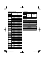
20
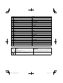
DH24PH
ITEM
NO.
PART NAME Q’TY
1FRONT CAP 1
2 STOPPER RING 1
3GRIP 1
4BALL HOLDER 1
5HOLDER PLATE 1
6HOLDER SPRING 1
7GEAR COVER 1
8NAME PLATE 1
9OIL SEAL 1
10 BALL BEARING 6805DD 1
11 P US HI NG BUTTON 1
12 PUSHING SPRING 1
13 CHANGE LEVER 1
14 O-RING (S-18) 1
15 HITACHI LABEL 1
16 SPRING (E) 1
17 BALL BEARING 608VVC2PS2L 3
18 STEEL BALL D7.00 1
19 CYLINDER 1
20 PIN D2.5 4
21 CYLINDER CLUTCH 1
22 SECOND GEAR 1
23 SPRING (A) 1
24 WASHER (A) 2
25
RETAINING RING FOR D30
SHAFT
1
26 OIL SEAL (A) 1
27 HAMMER HOLDER (C) 1
28 SLEEVE (FW) 1
29 SECOND HAMMER 1
30 HAMMER HOLDER (A) 1
31 DAMPER (A) 1
32 O-RING (C) 1
33 DAMPER HOLDER 1
34 STOPPER RING 1
35 STRIKER 1
36 O-RING D17 1
37 PISTON 1
38 PISTON PIN 1
39 PISTON WASHER 2
40 PINION SLEEVE (A) 1
41 LOCK PLATE 1
42 SECOND PINION 1
43 CLUTCH SPRING 1
44 CLUTCH 1
45 WASHER 1
46 SECOND SHAFT 1
47 RECIPROCATING BEARING 1
48 BEARING WASHER 1
49
SEAL LOCK HEX. SOCKET HD.
BOLT M5×16
2
50 BEARING HOLDER 1
ITEM
NO.
PART NAME Q’TY
51 BEARING COVER 1
52 FIRST GEAR 1
53 O-RING D72.2 1
54 INNER COVER 1
55 FELT PACKING 1
56 PACKING WASHER 1
57 O-RING (P-22) 1
58 BALL BEARING 608DDC2PS2L 1
59 WASHER (A) 2
60 ARMATURE 1
61 FAN GUIDE 1
62
HEX. HD. TAPP IN G SCREW
D4×50
2
63 STATOR 1
64 AIR CAP 1
65 FELT PACKING (A) 1
66 HOUSING 1
67
TAPPI NG SCREW (W/FLANGE)
D5×35
4
68 CORD 1
69 BRUSH HOLDER 2
70 CARBON BRUSH 1
71
CARBON BRUSH (AUTO STOP
TYPE)
1
72 PUSHING BUTTON 1
73 SWITCH 1
76 CORD ARMOR 1
77 CORD CLIP 1
78
TAPPI NG SCREW (W/FLANGE)
D4×16
2
79 NOISE SUPPRESSOR 1
80 CHOKE COIL (A) BROWN 1
81 CHOKE COIL (A) BLUE 1
82 HANDLE COVER 1
83
TAPPI NG SCREW (W/FLANGE)
D4×20
3
501 CASE 1
502 SIDE HANDLE 1
503 DEPTH GAUGE 1
Page is loading ...
Page is loading ...
Page is loading ...
Page is loading ...
-
 1
1
-
 2
2
-
 3
3
-
 4
4
-
 5
5
-
 6
6
-
 7
7
-
 8
8
-
 9
9
-
 10
10
-
 11
11
-
 12
12
-
 13
13
-
 14
14
-
 15
15
-
 16
16
-
 17
17
-
 18
18
-
 19
19
-
 20
20
-
 21
21
-
 22
22
-
 23
23
-
 24
24


Hitachi DH24PH Handling Instructions Manual
- Category
- Rotary hammers
- Type
- Handling Instructions Manual
Ask a question and I''ll find the answer in the document
Finding information in a document is now easier with AI
Related papers
-
Hitachi DH 22PH Instruction Manual And Safety Instructions
-
-
-
-
-
-
-
-
-
Other documents
-
 HiB Angled Grab Rail Fitting Instructions
-
Hikoki DH24PA User manual
-
 ITW Redhead SRM-34 Installation guide
-
Power Fist 8039067 User manual
-
Makita HR2652 SDS-Plus HEPA Rotary Hammer User manual
-
-
Milwaukee 5317-21 User manual
-
Ronix 2705 User manual
-
-

