
INSTRUCTION MANUAL
ED810 GAS DETECTOR
I N D E X
Page No.
IMPORTANT NOTE 2
ATEX REQUIREMENTS 2
MARKING 3
GENERAL 3
INSTALLATION 4
SOLENOID VALVE 5
SENSORS 6
OPERATING INSTRUCTIONS 7
CALIBRATION - SEMICONDUCTOR 7
CALIBRATION – HEAD ELECTRONICS 8
DECLARATION OF CONFORMITY 10
ED810 EC-TYPE EXAMINATION CERTIFICATE 11
ZB EC-TYPE EXAMINATION CERTIFICATE 14
ELECTRONIC DEVICES LIMITED
ENIGMA HOUSE, ENIGMA BUSINESS PARK, MALVERN, WORCESTERSHIRE WR14 1GD ENGLAND.
TELEPHONE : + 44 (0) 1684 891500 FACSIMILE: + 44 (0) 1684 891600 EMAIL: sales@ electronicdevice.demon.co.uk WEB SITE: www.electronicdevice.demon.co.uk
E

ED810 INSTRUCTION MANUAL 27-02-07 2
IMPORTANT
1.
The equipment supplied must not be modified in any way since modifications will
invalidate intrinsic safety certification, MCA and Lloyds approval.
2.
Care should be taken during servicing as high voltages may be present on the output
contacts.
3.
It is important to note that the ED810 contains four Zener Barriers, type ZB1, which are
“potted” in epoxy resin. The Zener Barriers contain fuses which once damaged are not
replaceable. The fuses inside the Zener Barrier will blow if even temporary short circuits
are placed on the sensor wiring thus rendering the Zener Barrier inoperable and not
repairable. Great care should therefore be taken to avoid inadvertent short circuits.
4.
Electronic Devices strongly recommend consultation of the HSE publication EH40,
which lists the permitted levels of exposure to most toxic gases.
ATEX ESSENTIAL SAFETY REQUIREMENTS
The ED810 gas detector, internally mounted Zener Barriers and associated gas sensors are
ATEX certified Intrinsically Safe and the following important requirements need to be
followed.
1. The equipment must only be installed, operated and maintained by trained competent
personnel.
2. This apparatus has been designed in accordance with EN50 014 and EN50 020,
therefore the apparatus has been designed to meet the fault tolerant requirements of
Associate Apparatus for Category 'ia'.
3. The installation and maintenance must be in accordance with all appropriate
international, national and local standard codes of practice and site regulations for
intrinsically safe apparatus.
4. The installation and maintenance must be in accordance with the instructions
contained in this installation and maintenance manual.
5. Access to the circuitry must not be made during operation.
6. This product is an associated electrical apparatus and must not be installed in the
hazardous area without the provision of further certified hazardous area protection.
7. The product must not be subjected to mechanical and thermal stresses in excess of
those permitted in the certification documentation and the instruction manual. If
necessary the product must be protected by an enclosure to prevent mechanical
damage.
8. The product must not be installed in a position where it may be attacked by
aggressive substances.
9. The product must be protected from excessive dust by an enclosure etc.
10. The product can not be repaired by the user and must be replaced by an equivalent
certified product. Repairs should only be carried out by the manufacturer or approved
service centre.

ED810 INSTRUCTION MANUAL 27-02-07 3
MARKING
All units have a rating label which carries the following important information:-
Model type: GAS DETECTOR TYPE ED810
Input voltage: 12Vdc/24Vdc (delete as appropriate)
Vmax in; Um: 250V
Code: [EEx ia] II C
Certificate no. Baseefa03ATEX0507
Epsilon x,
gas group II (1) G
and category:
CE marking,
Notified body
number:
Serial no. (serial number must be entered here)
Year of construction: (year of manufacture must be entered here)
GENERAL
The ED810 is a fixed installation gas detection system which can detect a wide range of
flammable and toxic gases dependent upon sensor type used.
The ED810 is designed for use in 12V or 24V DC insulated and earthed return electrical
systems. For insulated return systems special consideration should be given to the
“Hazardous Area common connection” terminal. This should normally be connected to a
good quality earth suitable for intrinsically safe equipment. However this terminal is
internally connected to 0V (-VE) of the DC supply and on insulated return installations may
produce an earth fault. Isolation can be provided by using a DC-DC inverter, or if mains is
available, a suitable linear power supply unit. Both are available from EDL.
Attention is drawn to the need for correct cabling, particularly to the sensors located in the
Hazardous Area. The cable supplied by EDL for use with the ED810 has been tested to
ensure correct parameters, see installation section of this manual.
Attention is also drawn to the need for calibration soon after installation. When supplied
alarm levels are approximately set for the target gas (if stated with order) so that a measure of
immediate protection is obtained once correct operation has been ensured.
1180

ED810 INSTRUCTION MANUAL 27-02-07 4
INSTALLATION
Note only EDL manufactured sensors, which are suitably certified can be connected to the
ED810 and fitted in the Hazardous Area. The ED810 control unit and all uncertified
equipment should be located in the Safe Area only.
Control Unit: The unit should be mounted in a convenient position for the operator away from
possible mechanical damage or ingress of moisture and allowing the clear hinged lid to swing
open for ease of calibration etc.
Remove the front cover by unscrewing the thumb screws and then removing the hinges. Fit
mounting screws in the slots now exposed. To obtain access to the two lower slotted holes
remove the terminal cover.
Note it is not usually necessary to remove the front panel and PCB assembly during
installation or calibration.
The power supply should not allow greater than 0.25V drop along its length when carrying
1A plus current required for ancillary equipment connected. Twin core double insulated 15A
cable is normally adequate. The main DC input fuse is normally 2A rated but may be
increased to 3A allowing for ancillary equipment. External fusing may be necessary and
should be considered.
The DC supply should not deviate by more than +/- 25% of the operating voltage stated on
the serial number label. It is advisable to wire the gas detector via its own main switch so that
it may become operational without having other electrical equipment energised. Allowing a
test for gas to be made without the danger of explosion through spark ignition.
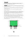
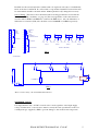
Sensor cable entry must only be made through the intended hole via either the standard
rubber grommet or cable gland. Sensor cables must not cross or lie over each other or safe
area cables see fig1 below.
FIG 1
BB PCB
TERMINAL BLOCK
RUBBER GROMMETS OR
CABLE GLAND KEEPING
CABLES SEPARATED
HAZARDOUS AREA CABLES
SAFE AREA CABLES

ED810 INSTRUCTION MANUAL 27-02-07 5
In addition to the zener barrier fuses (which cannot be replaced) each sensor is individually
fused on the base board PCB. If a sensor fails to respond the nominal 5V between blue and
brown terminals should be checked and the 160mA quick blow (F) changed if necessary.
Sensor Wiring: The Sensor cable should meet the following specification as listed in the
Zener Barrier (ZB1) certificate, see page 16. The total capacitance of the cable must not
exceed 6.8uF for EDS/C and EDS/P or 8.8uF for the EDF sensor. Also the inductance or
inductance to resistance (L/R) ratio should not exceed 0.06mH or 14uH/Ω respectively.
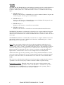
Typical output wiring: Fig 2 shows the terminal connections and Fig 3 shows typical wiring
of output functions. A fused 12V or 24V supply is available on terminal 2 for the operation
of low power sounders and beacons, the installation engineer must provide the links to
provide the required functions. Remember any sounders or beacons located in the Hazardous
Area must be certified Flameproof or Intrinsically Safe if fed via an external zener barrier
contact EDL for further information.
SOLENOID VALVE
It is important that only a 12VDC solenoid valve is used regardless of the input supply
voltage. Further more, solenoid valves must be exactly the same specification as the low
consumption type supplied by EDL to prevent damage to the circuit board components.
1 2 3 4
5 6
7
SOUNDER/BEACON
11
12
13 14
15
16 9
10
8
RELAY TO DRIVE
SHUT DOWN FUNCTIONS,
FANS, ETC.
1
2
3
4
5
6
7
8
9
10
11
12
13
14
15
16
17
18
19
20C
NO
NC
C
NO
NC
0V
FUSED 0/P
+VE I/P
NON
ALARM
ACCEPT
CONTACTS
A1 CONTACTS
HAZARDOUS
AREA
COMMON
-
+
VALVE
CONNECTIONS
12VDC EDL MODEL ONLY
NC
C
NO
A2 CONTACTS
NC
C
NO
FAULT CONTACTS
BL G/Y BR
(+VE) (-VE)(O/P)
BL G/Y BR
(+VE) (-VE)(O/P)
BL G/Y BR
(+VE) (-VE)(O/P)
BL G/Y BR
(+VE) (-VE)(O/P)
SENSOR 1 SENSOR 2 SENSOR 3 SENSOR 4
HAZARDOUS AREA WIRING
SAFE AREA WIRING
FIG 2
FIG 3
Relay contact rating: 2A at 240VAC Non Inductive

ED810 INSTRUCTION MANUAL 27-02-07 6
SENSORS
Type EDF 1B, 2B, 3B and 3Bfig are semiconductor elements housed in a certified flameproof
stainless steel housing. The housing has a male M32 thread which can be screwed into a
conduit or suitable junction box. The semiconductor sensors are available in the following
types:-
a) EDF1B flameproof.
Suitable for the detection of flammable gases such as Ammonia, Butane, Propane and
some toxic gases, for more gases see list available.
b) EDF2B flameproof.
Suitable for the detection of flammable gases such as Methane, Hydrogen and some
toxic gases, for more gases see list available.
c) EDF3B flameproof.
Suitable for the detection of most Freons such as R22.
d) EDF3B fig flameproof
Suitable for the detection of most Freons such as R11, R12, R143A, R134A etc.
The EDS/C IS Transmitter is a intrinsically safe junction box complete with head electronics
and electrochemical cell gas sensor suitable for the detection of various toxic gases. Many
different electrochemical cells are available and EDL should be consulted to advise on correct
sensor type.
The EDS/P IS Transmitter is a intrinsically safe junction box complete with head electronics
and catalytic (pellistor) gas sensor suitable for the detection of flammable gases. Contact
EDL for advice on correct sensor type.
Siting: The sensor heads should be placed lower than gas appliances when the gas to be
detected is heavier than air. If the gas is lighter than air then the sensors should be placed
above possible sources of leaks. Consideration should be given to the temperature of the gas
at the time during a leak, for example if a serious Ammonia leak occurs in a refrigeration
plant it can leak as a liquid and stay at floor level for some time even though Ammonia is
lighter than air. In this instance sensors at low and high levels are normally fitted.
Attention should be given to the probable gas flow in each particular installation to site the
sensors in the most advantagous position. In living quarters particular consideration should
be given to carbon monoxide, it is advisable that some of the sensors are mounted at head
height.
The sensors are sealed into their stainless steel enclosures and no attempt should be made to
open them on site, if necessary they should be returned to EDL for repair/servicing.
Unused sensor positions: When all of the sensor positions are not being used the spare
position should have the dip switches on the control PCB set to “standard sensors” and a
terminating resistor of 47KΩ fitted to avoid the fault lights and relay operating. This is
normally done before the unit leaves the factory as standard.

ED810 INSTRUCTION MANUAL 27-02-07 7
OPERATING INSTRUCTIONS
When power is first applied the power light should illuminate immediately. The A1 and A2
lights of semiconductor sensors will illuminate within a few seconds and will be ready to be
reset after a few minutes, provided the sensors are in clean air. The alarm lights and relays
latch and the reset switch must be pressed to clear any alarms.
The gas valve can be operated by pressing the “gas on” button. The gas valve will de-
energise automatically if the A1 alarm level is reached or if the power supply to the unit is
removed. The valve can be turned off manually by pressing the “gas off” switch.
The output functions can be easily tested by pressing the “alarm test” button. If the “alarm
accept” button is pressed any sounders or beacons connected will be muted.
When the input supply drops so low as the control unit cannot function correctly the low
voltage light will illuminate and the fault relay will activate.
Engineers override: should be used with caution as all ALARMS are disabled for a period of
approximately 30minutes. A hidden switch is located to the left of the reset switch. Pressed
through the front panel using a small screwdriver all Alarms are Isolated and the Fault Buzzer
sounds. Operate the hidden switch to the right of the Reset switch (keeping it pressed for
several seconds) and all Alarms will be returned to the operational state and the Fault Buzzer
will silence.
CALIBRATION
Before dispatch the alarm levels are approximately set for the target gas (if stated with order)
or set to 25% and 50% LEL butane so that a measure of immediate protection is obtained
once correct operation has been ensured.
Once the sensors and control unit have been in operation for a minimum of 24 hours
calibration can be attempted. Calibration should be repeated at least every twelve months with
regular checks in between.
Calibration must take place in a clean air condition to ensure accuracy.
Semiconductor sensors:
1. Immerse the sensor in the correct concentration for the A1 alarm, if using a continuous
flow do not use a flow rate of above 0.3L/min.
2. After allowing the sensor time to settle (10-20 seconds) adjust the appropriate
potentiometer located under the A1 light, accessed through the front panel. Rotating
clockwise increases sensitivity until the A1 light just illuminates, if the light comes on
prematurely wind anticlockwise whilst continuously pressing the reset switch until the
light goes out and then clockwise until it just illuminates.
3. Immerse the sensor in the correct concentration for the A2 alarm, if using a continuous
flow do not use a flow rate of above 0.3L/min.
4. After allowing the sensor time to settle (10-20 seconds) adjust the appropriate
potentiometer located under the A2 light, accessed through the front panel. Rotating
clockwise increases sensitivity until the A2 light just illuminates, if the light comes on
prematurely wind anticlockwise whilst continuously pressing the reset switch until the
light goes out and then clockwise until it just illuminates.
Repeat for all semiconductor sensors fitted.

ED810 INSTRUCTION MANUAL 27-02-07 8
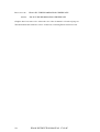
EDS/C and EDS/P Transmitters
INITIAL SETUP
It is vitally important that the ED810 and EDS/C or P transmitter are calibrated together
ensuring that the ED810 indicates an alarm at the correct concentration. After installation is
complete the following setup procedure should be followed matching the EDS/C or P, ED810
and cable run together.
EDS/C
1. At EDS/C transmitter measure between – I/P and + I/P, ensure voltage reading is in the
range 4.75 – 5.4V with a digital volt meter.
2. Using the correct calibration gas for your low alarm, ensure the calibration of the
EDSC Transmitter using the EDSC calibration instructions. Whilst the EDSC is
giving the correct output go to the ED810 control unit and adjust the A1 (located
under the A1 light, accessed through the front panel) potentiometer until the A1
light just illuminates. Rotating clockwise increases sensitivity until the A1 light
just illuminates, if the light comes on prematurely wind anticlockwise whilst
continuously pressing the reset switch until the light goes out and then clockwise
until it just illuminates.
3.
Using the correct calibration gas for your high alarm, ensure the calibration of the
EDSC Transmitter using the EDSC calibration instructions. Whilst the EDSC is
giving the correct output go to the ED810 control unit and adjust the A2 (located
under the A2 light, accessed through the front panel) potentiometer until the A2
light just illuminates. Rotating clockwise increases sensitivity until the A2 light
just illuminates, if the light comes on prematurely wind anticlockwise whilst
continuously pressing the reset switch until the light goes out and then clockwise
until it just illuminates.
Example of calculating expected output voltage
The output of the EDSC
*
ranges from 0.1 to 0.5V (zero to full scale). If Full scale is
1000ppm NH3 then :
250ppm output : (0.4 x 0.25 + 0.1) = 0.2V
500ppm output: (0.4 x 0.5 + 0.1) = 0.3V
1000ppm output: (0.4 x 1 + 0.1) = 0.5V
BROWN
G/Y
SAFE AREA HAZARDOUS AREA
Grn/Yel
Blue
Brn
Sensor
Terminals
-VE I/P (0V)
+VE I/P
0.
1
–
0
.
5
V
o/p
Power/Output
Terminals
BLUE
EDS/C orP TRANSMITTER
SENSOR
ED810

ED810 INSTRUCTION MANUAL 27-02-07 9
EDS/P
1. At EDS/P transmitter measure between – I/P and + I/P, ensure voltage reading is in the
range 4.0 – 5.4V with a Digital volt meter.
2. Using the Zero adjustment potentiometer on the EDS/P, rotate clockwise until the 50%
lamp is just illuminated or 0.3V is measured on the O/P terminal w.r.t 0V.
4. Go to the ED810 Control unit and adjust the A1 potentiometer (located below the A1
light and accessed through the front panel) until the A1 light just illuminates. Rotating
clockwise increases sensitivity until the A1 light just illuminates, if the light comes on
prematurely wind anticlockwise whilst continuously pressing the reset switch until the
light goes out and then clockwise until it just illuminates.
3. Back at the EDS/P again using the Zero adjustment potentiometer on the EDS/P, rotate
clockwise until the 100% lamp is just illuminated or 0.5V is measured on the O/P
terminal w.r.t 0V.
4. Go to the ED810 Control unit and adjust the A2 potentiometer (located below the A2
light and accessed through the front panel)until the A2 light just illuminates.
5. Using the EDS/P instructions return the output to Zero and calibrate the sensor.
Remember the Sensor requires a minimum of 24 hours to settle otherwise the calibration
WILL NOT be accurate.
Example of calculating expected output voltage
The output of the EDSP
*
ranges from 0.1 to 0.5V (0 to full scale). If Full scale is 10,000ppm
NH3 then :
2,500ppm output : (0.4 x 0.25) + 0.1 = 0.2V
5,000ppm output: (0.4 x 0.5) + 0.1 = 0.3V
10,000ppm output: (0.4 x 1) + 0.1 = 0.5V
*
The output range stated is correct when the EDSC / EDSP is connected to the ED810,
if tested separately the output range will be 0.2 to 1.0VDC.

ED810 INSTRUCTION MANUAL 27-02-07 10
Please note the - ED810 EC-TYPE EXAMINATION CERTIFICATE
And the ZB EC-TYPE EXAMINATION CERTIFICATE
Graphics have been removed to reduce the size of the document for download purposes.
The full manual and certificates can be obtained by contacting Electronic Devices ltd.
-
 1
1
-
 2
2
-
 3
3
-
 4
4
-
 5
5
-
 6
6
-
 7
7
-
 8
8
-
 9
9
-
 10
10


Barnet Ensign Ross Carbon Monoxide Alarm ED810 User manual
- Type
- User manual
- This manual is also suitable for
Ask a question and I''ll find the answer in the document
Finding information in a document is now easier with AI
Other documents
-
RKI Instruments GD-K88Ai Owner's manual
-
Omega SBG54806 Owner's manual
-
-
Pepperl+Fuchs Z960 Owner's manual
-
-
 SEAV EASY LED User guide
-
Rae FMC-40 Operating Handbook
-
Danfoss Level transmitter AKS 41 Installation guide
-
-
Comet T3113Ex Owner's manual
